EP0128593A2 - Methode zum Steuern des Betriebs eines thermoelektrischen Kraftwerks - Google Patents
Methode zum Steuern des Betriebs eines thermoelektrischen Kraftwerks Download PDFInfo
- Publication number
- EP0128593A2 EP0128593A2 EP84106819A EP84106819A EP0128593A2 EP 0128593 A2 EP0128593 A2 EP 0128593A2 EP 84106819 A EP84106819 A EP 84106819A EP 84106819 A EP84106819 A EP 84106819A EP 0128593 A2 EP0128593 A2 EP 0128593A2
- Authority
- EP
- European Patent Office
- Prior art keywords
- turbine
- boiler
- stress
- plant
- steam
- Prior art date
- Legal status (The legal status is an assumption and is not a legal conclusion. Google has not performed a legal analysis and makes no representation as to the accuracy of the status listed.)
- Granted
Links
Images


Classifications
-
- F—MECHANICAL ENGINEERING; LIGHTING; HEATING; WEAPONS; BLASTING
- F22—STEAM GENERATION
- F22B—METHODS OF STEAM GENERATION; STEAM BOILERS
- F22B35/00—Control systems for steam boilers
- F22B35/18—Applications of computers to steam-boiler control
-
- F—MECHANICAL ENGINEERING; LIGHTING; HEATING; WEAPONS; BLASTING
- F01—MACHINES OR ENGINES IN GENERAL; ENGINE PLANTS IN GENERAL; STEAM ENGINES
- F01K—STEAM ENGINE PLANTS; STEAM ACCUMULATORS; ENGINE PLANTS NOT OTHERWISE PROVIDED FOR; ENGINES USING SPECIAL WORKING FLUIDS OR CYCLES
- F01K13/00—General layout or general methods of operation of complete plants
- F01K13/02—Controlling, e.g. stopping or starting
Definitions
- the present invention relates to a method of controlling the operation of a thermoelectric power station and, more particularly, to a method which permits a quick start up of the plant while keeping the thermal stress occurring in the thick-walled part of the plant below a predetermined allowable level.
- thermoelectric power plants are used for medium levels of load to work in harmonization with nuclear power plants.
- the.operation of the steam generating equipment,as well as the operation of the turbines is controlled in accordance with plant operating parameters which are obtained from given patterns of start up and operation of the plant.
- These thermoelectric power plants are required also to respond to the demands for quick start up and stop, as well as the demand for drastic change of the load level. It is, therefore, quite important to precisely determine the thermal stresses occurring in the thick-walled parts of the steam generating equipment and turbine, and to control the start up and stopping of the plant, as well as the running of the same, in such a manner as to minimize the consumption an ⁇ the reduction of the lifetimes of these parts.
- an object of the invention is to provide a method of starting up a thermoelectric plant which permits an efficient use of the life consumption allotted for each start up and operation of the plant, while keeping the thermal stresses in the thick-walled parts in the plant below predetermined allowable levels and minimizing the time length required for the starting up of the plant.
- thermoelectric power generating plant having a steam generating equipment and a turbine
- said method comprising: assuming temporarily plant operation parameters concerning the rates of change in various conditions of the plant such as the rate of temperature rise of main steam, rate of acceleration of turbine, rate of change of the load; estimating the change in the quantity of state of the main steam temperature; estimating the thermal stresses in the stress-evaluation portions of the steam generating equipment and turbine on the basis of said parameters; comparing the estimated thermal stresses with the value of the thermal stress determined to correspond to the life consumption allowed for each of the start up and operation cycles; selecting one parameter which provides smaller deviation of the thermal stress from the allowable stress value while affording the maximum rate of change of the state of the plant, i.e., the most quick start up of the plant; and controlling the operation of the steam generating equipment and the turbine in accordance with the thus selected operation parameter.
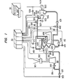
- Fig. 1 is a block diagram schematically showing the concept of a thermoelectric power generating plant which is to be controlled by the method of the invention.
- a reference numeral 10 denotes a control desk
- 20 denotes a digital computer
- 30 denotes a coal mill system as an example of the fuel supplying system
- 40 denotes a steam generating equipment ((referred to as "boiler system", hereinunder)
- 50 denotes a turbine generator system.
- thermoelectric power generating system the operator conducts the necessary operation from the control desk 10, in accordance with data on various parts of the plant given through the computer 20, as well as the data delivered by a commanding control station such as a central power supply controlling headquarter.
- the computer 20 delivers various control signals required for all controlled portions of the plant upon receipt of data on various parts of the plant and signals derived from the control desk 10.
- the coal mill system 30 is constituted by a coal banker 301, coal feeder 302, pulverizer 310, blowers 321,322, and dampers 323,324.
- the coal is supplied to the mill 310 through the banker 301 and the coal feeder 302, and is pulverized into fine pulverized coal in the mill 310.
- the pulverized coal is carried away by the air blown by the blowers321,322 to the burner 407 of the boiler system 40 so as to be burnt in the boiler system 40.
- the computer 20 receives, for the purpose of controlling the coal mill system 30, the flow rate of secondary air by means of, for example, a sensor 343.
- the computer 20 operates the coal feeder 302 to control the rate of feed of the coal, and operates also a damper 323 for controlling the total air, as well as a damper 324 for controlling the primary air (coal conveying air).
- the boiler system 40 has a feedwater pump 401, feedwater control valve 402, evaporator 403, primary superheater 404, secondarysuperheater 405, chimney 409, gas recirculating blower 406 and the burner 407 mentioned before.
- the water supplied by the feedwater pump 401 is changed into steam by the evaporator 403, and is changed into superheated main steam as it flows through the primary and secondary superheaters 404,405.
- the main steam is introduced into the turbine generator system 50.
- the heat produced by the fuel coal burnt in the burner 407 is utilized in converting the water into steam in the evaporator 403 and also in heating the steam into superheated steam within the superheaters 404,405. A part of the heat, however, is wasted into the air through the chimney 409.
- Part of the gas emitted from the chimney 409 is returned by the recirculating blower 406 to the boiler so as to be used for the purpose of, for example, diminishing the generation of nitrogen oxides.
- the control valve 402 is controlled by the output of the computer 20.
- feed water supply rate, steam temperature at the inlet to the primary superheater, steam flow rate, main steam temperature, main steam pressure and the recirculated gas flow rate are sensed by respective sensors 411,412,413,414,415 and 416 and sent to the computer 20.
- the turbine generator system 50 has a turbine control valve 501, high-pressure turbine 502, medium/low pressure turbine 503, condenser 504 and a generator 505 directly connected to the turbine rotors.
- the computer 20 receives signals from sensors 506, 507, 508 and 509 which sense the steam pressure behind the first stage of the turbine, turbine speed,the steam temperature behind the first stage, and the electric power.
- the main steam is supplied to the turbines 502 and 503 at flow rates regulated by the control valve 501 which in turn is operated by the output from the cmputer 20.
- the steam after expansion through the turbine is cooled and condensed to become condensate in the condenser 504.
- the condensate is then fed as the feed water to the boiler by means of the feed water pump 401.
- the electric power sensed by the sensor 509 is delivered to the computer 20.
- thermoelectric power generating plant Various demands concerning the operation of the plant are given to the computer 20 through the control desk 10. In response to these demands, the computer 20 outputs control signals taking into account the data obtained from the plant and the programs which are given beforehand, thereby to control the operation of the plant to achieve the aimed condition. This is the outline of the construction of the thermoelectric power generating plant.
- thermoelectric power generating plant when the plant is being started up.
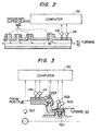
- Fig. 2 is a sectional view of the outlet tube header of the secondary superheater 405 of the boiler system.
- a plurality of tubes of the secondary superheater merge in one another in this tube header.
- the tube header is not heated externally but is heated only internally by the internal fluid, i.e., the superheated steam. Since the header has a considerable wall thickness, the header portion experiences a large temperature difference between the inner surface and outer surface thereof, so that a large thermal stress occurs particularly at the nozzle corner portion Nc.
- the main steam flow rate MSF, the main steam temperature MST and the main steam pressure MSP are sensed by sensors 413, 414 and 415.
- the heat transfer coefficient h is given by the following formula (3) : where,
- Fig. 6a shows the boundary condition (formula(2)) of the heat diffusion system expressed by formula (1).
- the amount of heat transferred from the steam to the metal inner surface is given by h(Tf - Ta), while the heat conduction in the metal is given by .
- the thermal stress at any desired point of radius 6 in Fig. 6a is determined by a polar coordinate system as follows. Namely, the radial termal stressu ⁇ r (r), circumferential thermal stress ⁇ (r) and the axial thermal stress ⁇ z (r) are given by the )following formulae (4) to (6).
- the stresses in this point are determined by the following formulae (4)', (5)' and (6)' by substituting a for r in the formulae (4),(5) and (6), respectively.
- the stress value a 6 (a) is used as the representative value for the evaluation of thermal stress in an ordinary portion of the cylinder.
- symbols Ml and M2 represent memories.
- the memory Ml stores the temperatures To(j) to T N (j) at respective points of division of metal as shown in Fig. 6(b), as well as the steam temperature Tf(j), while M2 stores the temperatures To(j+l) to T N (j+1) at respective points of division of the metal after the execution of the equation Al, as well as the steam temperature Tf(j+l).
- the temperatures To(j+l) to T N (j+l) and Tf(j+l) are temperatures after the sampling period At of the computer.
- the equation Al is the difference equation expanded from the formulae (1) and (2) for each point of division.
- the equation 101-Tf represents the heat transfer on the metal inner surface
- 101-Tk represents the heat transfer at the point k of division.
- the equation Al is executed on the basis of To(j+l) to Tn(j+l) and Tf(j+l) to determine Ts(j+2) to T N (j+2) and Tf(j+2). These values represent the temperature distribution at the moment 2 ⁇ t thereafter.
- the metal temperatures To(tl), T 1 (tl), etcT N (tl) and the temperature Tf(tl) of the internal fluid at the moment tl are thus determined as shown in Fig. 8. Using these values as the initial values, it is possible to calculate the temperature distribution To (t1+n ⁇ t), T 1 (t1+n. ⁇ t),...., T N (tl+n. ⁇ t) at the moment n.At thereafter, by repeating the calculation by n times.
- the heat diffusion factor .a and the heat conductivity ⁇ appearing in Fig. 8 take different values depending on the metal temperatures. Therefore, the volumetric mean temperature Tar of the temperatures T 0 ,T 1 ?? T N at metal dividing points is determined and the diffusion rate a and the heat conductivity ⁇ are stored beforehand to permit selection of values thereof corresponding to the volumetric mean temperature Tar.
- the metal temperature distribution is thus determined by the computer 20 and then the thermal stress is calculated.
- the thermal stress can be determined by the formula (7).
- the steam condition i.e. the flow rate and the pressure of the internalfluid
- the temperature Tf of the internal fluid is fluctuated so that a large difference may be caused between the actual stress and the estimated stress determined in accordance with the formula (7)' on the assumption that the internal fluid temperature Tf is constant. It is, therefore, preferred to estimate the future internal fluid temperature from the present value Tf (t 1 ), Various measures can be taken for the estimation. For instance, the estimation is conducted by the formula of: where, Rj is the rate of temperature rise as obtained from the temperature change experienced in thepast. Fig.
- the method explained hereinunder employs a model of the start-up characteristics of the secondary superheater for the estimation of the main steam temperature, namely, the main steam temperature Tf(t + n. ⁇ t) at the moment n. ⁇ t (n being an integer, At being the computation period), by repeating the computation of the following formulae for n times.
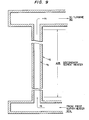
- Fig. 9 shows the secondary superheater 405 and the tube header annexed thereto.
- the start-up characteristics of the secondary superheater can be expressed as follows, using the Law of energy preservation and the heat transfer formula (1), on an assumption that the heat transfer to the seconday superheater is made at a constant pressure, taking into account small fluctuations of the variables in the steady condition of the superheater.
- the maximum estimated value x ⁇ (i) of the signal X(i) can be determined by the following formula (19), using the theory of Karman filter: where, represents the estimated amount of the model which is given by the following formula (20). where, wherein,
- the main steam temperature may be estimated for a certain period of time thereafter, from the rate of change in the state of the plant set as the plant operation parameter.
- Fig. 3 is a sectional view of the high-pressure turbine in the turbine generator system 50, particularly the portion 541 adjacent to the labyrinth packing behind the first stage.
- this portion of the turbine experiences the greatest thermal stress.
- the rotor portion adjacent to this labyrinth packing is subjected to the most severe condition, because the temperature, pressure and velocity of the steam leaking through this packing fluctuate largely when the turbine is started up. Consequently, this portion is subjected to a quick and repetitional heating and cooling and, hence, tends to experience excessive thermal stress.
- the main steam temperature, the main steam pressure, the steam temperature Tlst behind the first stage and the steam pressure behind the first stage are sensed by sensors 414, 415, 508 and 506, respectively.
- the temperature distribution of the rotor member will be calculated.
- the temperature distribution of the rotor is given by the formula (1) mentioned before.
- the symbol a is the heat conductivity of the rotor material
- T represents the temperature in the rotor at a radius r from the rotor axis, at a moment t.
- the Nusselt number Nu is given by: 1o where,
- Fig. 4 is a diagram showing the plant start-up characteristics of the thermoelectric power generating plant.
- the axis of abscissa represents the time t, while the axis of ordinate show various values.
- symbol MST shows the main steam temperature (°C)
- TV represents the turbine velocity (RPM)
- PL represents the power load (MW).
- t l represents the moment at which the fire is set
- t 2 represents the moment of commencement of steaming
- t 3 shows the moment of connection to the electric power line
- t 4 shows the moment of change-over of the valves.
- control is conducted using mainly one of the calculated values of the thermal stress in the boiler and the thermal stress in the turbine, having the smaller margin.
- the maximum rates of the load change, temperature rise and pressure rise are selected within the range of allowable thermal stress in the turbine, and the turbine is controlled in accordance with the selected rates.
- the boiler system 40 is controlled in accordance with the rates of change of other states of the plant. In some cases, it is required to increase the load or the steam condition to the rated level in the shortest time. For loading the turbine with the minimum time length, the maximum rate of load increase is selected within the range which does not cause the thermal stress exceeding the allowable level in the turbine. Controlling the loading of the turbine at this rate, the rate of temperature rise and pressure rise of the steam are changed in accordance with the load change.
- the maximum rates of increase of steam temperature and pressure are selected within the range which does not cause thermal stress exceeding the allowable stress in the boiler, and the control is made in accordance with the maximum load changing rate selected under such a steam condition.
- thermoelectric power generating plant can be started up within minimum time, safely and with asufficient margin of the thermal stress, in response to the state of operation of the thermoelectric power generating plant.
- either one of the maximum rate of start-up of the turbine and the maximum rate of start-up of the boiler, which causes the smaller difference of the thermal stress value from the allowable stress level, is selected and used as the maximum rate of change of state of the plant, and the boiler or the turbine is controlled in accordance with this maximum changing rate of the state of the plant.
- a step 200 the operator 1 operates the control desk 10 to set in the operation parameter setting area of the cmputer 20 various operation parameters such as the plant start-up pattern, operation pattern, allowable thermal stress in boiler (header tube of secondary superheater), allowable thermal stress in the turbine rotor (rotor portion adjacent to labyrinth packing of first stage), and so on.
- maximum values of the load changing rate and acceleration rate of the turbine 502, as well as the maximum values of the increasing rates of the steam temperature and pressure of the boiler system 40 are determined on the basis of the plant starting-up and operation patterns stored in the predetermined areas of the memory, and are temporarily set in another area of the memory.
- a computation is made to decide the estimate time, i.e., the future moment at which the thermal stresses are to be estimated.
- the estimation time is dicided in accordance with the level of the heat transfer coefficient at the stress evaluation portion such as the portion 504 adjacent to the labyrinth packing, i.e., the state of operation of the plant.
- a step 203 computation is made on the basis of the decided estimate time to estimate the steam condition by using, for instance, formulae (16) and (19) explained before.
- the process then proceeds to a step 204, in which the temperature distribution in the stress evaluation portion (tube header of secondary superheater) of the boiler system 40 is computed.
- a computation is conducted to estimate the thermal stress in the tube header of the secondary superheater. Note that this estimation is based on the assumed changing rate mentioned before.
- a step 206 the estimated thermal stress is compared with the allowable thermal stress which was beforehand stored in the setting area of the computer 20 by the operator 1 . , thereby to determine the margin of the thermal stress.
- the thermal stress is computed also for the turbine and the margin of the thermal stress in the turbine is stored in a predetermined area of the memory of the computer 20.
- a judgement is made to identify the period of operation, among the periods i) to iv) explained before in connection with Fig. 4.
- the thermal stress value estimated with the boiler is chosen, whereas, if the present period is the period ii), the estimated thermal stress value in the turbine is selected.
- the present period is the period iv
- the priority is given to this one of the estimated thermal stress values which has the smaller margin.
- step 212 The result of the judgement made in the step 211 is given to the step 212.
- the estimated thermal stress value selected in the step 212 is compared with the allowable thermal stress level which was beforehand set by the operator 1, and a plant operation parameter which can maximize the rate of change of the state of the plant without causing the thermal stress to exceed the allowable stress is selected.
- the rate of change of the state of the plant which was temporarily set in the setting area of the memory of the computer, is corrected in accordance with the thus selected changing rate of the state of the plant.
- a step 212 the temperature rising rate and the pressure increasing rate are inputted to the boiler steam temperature controlling function 220.
- the acceleration rate and load increasing rate are given to the turbine speed and load control function230.
- the process proceeds to a step 213 in which a judgement is made as to whether the command value (completion of start-up or operation) has been reached, at each time of setting of the plant state changing rate. If the command has not been reached yet, the process is returned to the step 201. However, if the command is reached in the step 213, the control of the operation is finished.
Landscapes
- Engineering & Computer Science (AREA)
- Chemical & Material Sciences (AREA)
- Combustion & Propulsion (AREA)
- Mechanical Engineering (AREA)
- General Engineering & Computer Science (AREA)
- Physics & Mathematics (AREA)
- Thermal Sciences (AREA)
- Control Of Turbines (AREA)
- Feedback Control In General (AREA)
Applications Claiming Priority (2)
| Application Number | Priority Date | Filing Date | Title |
|---|---|---|---|
| JP58106271A JPS59231604A (ja) | 1983-06-14 | 1983-06-14 | 火力発電プラントの運転制御方法 |
| JP106271/83 | 1983-06-14 |
Publications (3)
| Publication Number | Publication Date |
|---|---|
| EP0128593A2 true EP0128593A2 (de) | 1984-12-19 |
| EP0128593A3 EP0128593A3 (en) | 1985-10-23 |
| EP0128593B1 EP0128593B1 (de) | 1990-05-09 |
Family
ID=14429414
Family Applications (1)
| Application Number | Title | Priority Date | Filing Date |
|---|---|---|---|
| EP84106819A Expired EP0128593B1 (de) | 1983-06-14 | 1984-06-14 | Methode zum Steuern des Betriebs eines thermoelektrischen Kraftwerks |
Country Status (4)
| Country | Link |
|---|---|
| US (1) | US4558227A (de) |
| EP (1) | EP0128593B1 (de) |
| JP (1) | JPS59231604A (de) |
| DE (1) | DE3482200D1 (de) |
Cited By (6)
| Publication number | Priority date | Publication date | Assignee | Title |
|---|---|---|---|---|
| EP0266771A3 (en) * | 1986-11-06 | 1989-12-20 | Babcock-Hitachi Kabushiki Kaisha | Boiler control system |
| EP0316806A3 (en) * | 1987-11-13 | 1990-07-25 | Babcock-Hitachi Kabushiki Kaisha | Apparatus for controlling boiler/turbine plant |
| WO2001057366A1 (de) * | 2000-02-02 | 2001-08-09 | Siemens Aktiengesellschaft | Verfahren zum betreiben einer turbine und turbinenanlage |
| DE10221594A1 (de) * | 2002-05-15 | 2003-11-27 | Kuehnle Kopp Kausch Ag | Vorrichtung und Verfahren zur wirkungsgradoptimierten Regelung einer Turbine |
| WO2007090482A1 (de) * | 2006-02-06 | 2007-08-16 | Siemens Aktiengesellschaft | Verfahren und vorrichtung zum vorausschauenden bestimmen einer temperaturverteilung in einer wand einer turbinenanlage |
| EP2837777A1 (de) * | 2013-08-16 | 2015-02-18 | ABB Technology AG | Verfahren zur Berechnung von Wärmespannung in dickwandigen Komponenten eines Wärmesystems |
Families Citing this family (27)
| Publication number | Priority date | Publication date | Assignee | Title |
|---|---|---|---|---|
| JPS61275905A (ja) * | 1985-05-31 | 1986-12-06 | Syst Sogo Kaihatsu Kk | 多入力多出力系制御用制御装置 |
| US5157619A (en) * | 1988-10-31 | 1992-10-20 | Westinghouse Electric Corp. | Abnormal thermal loading effects monitoring system |
| JP3095294B2 (ja) * | 1992-09-18 | 2000-10-03 | 株式会社日立製作所 | プラントの制御システム |
| US5277244A (en) * | 1992-10-20 | 1994-01-11 | Hunter Fan Company | Relay contact monitoring system |
| KR20000053135A (ko) * | 1996-11-08 | 2000-08-25 | 칼 하인쯔 호르닝어 | 터빈의 부하 교번 과정을 조절하기 위한 터빈 제어 장치 및 방법 |
| DE19910222C2 (de) * | 1999-03-09 | 2002-02-28 | Abb Patent Gmbh | Verfahren und Einrichtung zur Bestimmung einer Dampftemperatur |
| DE10060706A1 (de) | 2000-12-07 | 2002-06-13 | Flowtec Ag | Verfahren und eine Vorrichtung zur System- und/oder Prozeßüberwachung |
| GB2374904A (en) * | 2001-04-26 | 2002-10-30 | Bowman Power Systems Ltd | Controlling temperature in gas turbine apparatus during startup or shutdown |
| DE102004058171A1 (de) * | 2004-10-02 | 2006-04-06 | Abb Technology Ag | Verfahren und Modul zum vorrausschauenden Anfahren von Dampfturbinen |
| US7174715B2 (en) * | 2005-02-02 | 2007-02-13 | Siemens Power Generation, Inc. | Hot to cold steam transformer for turbine systems |
| US9335042B2 (en) * | 2010-08-16 | 2016-05-10 | Emerson Process Management Power & Water Solutions, Inc. | Steam temperature control using dynamic matrix control |
| US9328633B2 (en) | 2012-06-04 | 2016-05-03 | General Electric Company | Control of steam temperature in combined cycle power plant |
| JP6037448B2 (ja) * | 2013-03-15 | 2016-12-07 | 三菱日立パワーシステムズ株式会社 | 蒸気タービン発電プラント |
| DE102014205627B3 (de) * | 2014-03-26 | 2015-06-18 | Siemens Aktiengesellschaft | Zustandsbeobachter für einen Dampferzeuger eines Dampfkraftwerks |
| CN104089270B (zh) * | 2014-07-11 | 2016-03-30 | 国家电网公司 | 一种发电机组锅炉负荷控制优化调整试验方法 |
| US10375901B2 (en) | 2014-12-09 | 2019-08-13 | Mtd Products Inc | Blower/vacuum |
| JP6498059B2 (ja) * | 2015-06-30 | 2019-04-10 | 三菱日立パワーシステムズ株式会社 | 起動制御装置 |
| US10267182B2 (en) * | 2015-07-01 | 2019-04-23 | Emerson Process Management Power & Water Solutions, Inc. | Methods and apparatus to optimize steam turbine ramp rates |
| US10781723B2 (en) | 2015-07-24 | 2020-09-22 | Emerson Process Management Power And Water Solutions, Inc. | Methods and apparatus to optimize steam header blending and gas turbine loading in combined cycle power plants |
| US10954824B2 (en) | 2016-12-19 | 2021-03-23 | General Electric Company | Systems and methods for controlling drum levels using flow |
| US10677102B2 (en) * | 2017-02-07 | 2020-06-09 | General Electric Company | Systems and methods for controlling machinery stress via temperature trajectory |
| EP3495732B1 (de) | 2017-12-08 | 2024-02-14 | General Electric Technology GmbH | Zwangsdurchlaufverdampfersysteme |
| EP3495729B1 (de) | 2017-12-08 | 2020-11-25 | General Electric Technology GmbH | Zwangsdurchlaufverdampfersysteme |
| EP3495730B1 (de) * | 2017-12-08 | 2024-01-24 | General Electric Technology GmbH | Zwangsdurchlaufverdampfersysteme |
| EP3495731B1 (de) * | 2017-12-08 | 2022-02-16 | General Electric Technology GmbH | Einmaldurchlaufverdampfersysteme |
| CN110043918B (zh) * | 2019-04-18 | 2024-04-02 | 中国大唐集团科学技术研究院有限公司华东电力试验研究院 | 一种带暖风器的邻炉加热启动系统 |
| CN116116558B (zh) * | 2023-01-12 | 2025-01-24 | 浙江浙能技术研究院有限公司 | 稀土电机中速磨煤机变速调节控制锅炉冷态启动的方法 |
Family Cites Families (16)
| Publication number | Priority date | Publication date | Assignee | Title |
|---|---|---|---|---|
| US3446224A (en) * | 1967-01-03 | 1969-05-27 | Gen Electric | Rotor stress controlled startup system |
| SE376961B (de) * | 1967-09-11 | 1975-06-16 | Svenska Maskinverken Ab | |
| US3561216A (en) * | 1969-03-19 | 1971-02-09 | Gen Electric | Thermal stress controlled loading of steam turbine-generators |
| US3928972A (en) * | 1973-02-13 | 1975-12-30 | Westinghouse Electric Corp | System and method for improved steam turbine operation |
| US4053747A (en) * | 1973-11-06 | 1977-10-11 | Westinghouse Electric Corporation | System for initializing a backup computer in a multiple computer electric power plant and turbine control system to provide turbine and plant operation with reduced time for backup computer availability |
| US4181840A (en) * | 1975-02-13 | 1980-01-01 | Westinghouse Electric Corp. | Anticipative turbine control |
| US4029951A (en) * | 1975-10-21 | 1977-06-14 | Westinghouse Electric Corporation | Turbine power plant automatic control system |
| FR2380418A1 (fr) * | 1977-02-09 | 1978-09-08 | Europ Turb Vapeur | Procede pour la conduite d'un ensemble de production d'energie |
| GB2002543B (en) * | 1977-07-29 | 1982-02-17 | Hitachi Ltd | Rotor-stress preestimating turbine control system |
| JPS585626B2 (ja) * | 1978-07-29 | 1983-02-01 | 日本電気ホームエレクトロニクス株式会社 | 映像信号の合成方法 |
| US4297848A (en) * | 1979-11-27 | 1981-11-03 | Westinghouse Electric Corp. | Method of optimizing the efficiency of a steam turbine power plant |
| JPS576203A (en) * | 1980-06-11 | 1982-01-13 | Hitachi Ltd | Boiler steam temperature control system |
| JPS57179509A (en) * | 1981-04-28 | 1982-11-05 | Tokyo Shibaura Electric Co | Method of controlling temperature of superheated steam of boiler |
| JPS57197606A (en) * | 1981-05-30 | 1982-12-03 | Toshiba Corp | Operation controller of plant |
| JPS5843002A (ja) * | 1981-09-07 | 1983-03-12 | Hitachi Ltd | 火力発電プラントの効率最適化制御方法 |
| JPS5843004A (ja) * | 1981-09-07 | 1983-03-12 | Hitachi Ltd | 火力発電プラントの効率最適化制御方法 |
-
1983
- 1983-06-14 JP JP58106271A patent/JPS59231604A/ja active Granted
-
1984
- 1984-06-08 US US06/618,676 patent/US4558227A/en not_active Expired - Lifetime
- 1984-06-14 EP EP84106819A patent/EP0128593B1/de not_active Expired
- 1984-06-14 DE DE8484106819T patent/DE3482200D1/de not_active Expired - Lifetime
Cited By (8)
| Publication number | Priority date | Publication date | Assignee | Title |
|---|---|---|---|---|
| EP0266771A3 (en) * | 1986-11-06 | 1989-12-20 | Babcock-Hitachi Kabushiki Kaisha | Boiler control system |
| EP0316806A3 (en) * | 1987-11-13 | 1990-07-25 | Babcock-Hitachi Kabushiki Kaisha | Apparatus for controlling boiler/turbine plant |
| WO2001057366A1 (de) * | 2000-02-02 | 2001-08-09 | Siemens Aktiengesellschaft | Verfahren zum betreiben einer turbine und turbinenanlage |
| US6647728B2 (en) * | 2000-02-02 | 2003-11-18 | Siemens Aktiengesellschaft | Method for operating a turbine and turbine installation |
| DE10221594A1 (de) * | 2002-05-15 | 2003-11-27 | Kuehnle Kopp Kausch Ag | Vorrichtung und Verfahren zur wirkungsgradoptimierten Regelung einer Turbine |
| DE10221594B4 (de) * | 2002-05-15 | 2006-02-16 | AKTIENGESELLSCHAFT KüHNLE, KOPP & KAUSCH | Vorrichtung und Verfahren zur wirkungsgradoptimierten Regelung einer Turbine |
| WO2007090482A1 (de) * | 2006-02-06 | 2007-08-16 | Siemens Aktiengesellschaft | Verfahren und vorrichtung zum vorausschauenden bestimmen einer temperaturverteilung in einer wand einer turbinenanlage |
| EP2837777A1 (de) * | 2013-08-16 | 2015-02-18 | ABB Technology AG | Verfahren zur Berechnung von Wärmespannung in dickwandigen Komponenten eines Wärmesystems |
Also Published As
| Publication number | Publication date |
|---|---|
| EP0128593A3 (en) | 1985-10-23 |
| US4558227A (en) | 1985-12-10 |
| JPS59231604A (ja) | 1984-12-26 |
| DE3482200D1 (de) | 1990-06-13 |
| EP0128593B1 (de) | 1990-05-09 |
| JPH0521241B2 (de) | 1993-03-23 |
Similar Documents
| Publication | Publication Date | Title |
|---|---|---|
| EP0128593B1 (de) | Methode zum Steuern des Betriebs eines thermoelektrischen Kraftwerks | |
| EP0282172B1 (de) | Regelsystem für Wärmetauscher | |
| EP0034614B1 (de) | Steuerungssystem für einen cheng-gas-dampfturbinenprozess | |
| CN102374518B (zh) | 使用动态矩阵控制的蒸汽温度控制 | |
| US3038453A (en) | Apparatus and method for controlling a forced flow once-through steam generator | |
| US4425762A (en) | Method and system for controlling boiler superheated steam temperature | |
| CN107292006B (zh) | 一种超临界锅炉的启动计算方法及系统 | |
| JP2014519009A (ja) | 循環廃熱回収蒸気発生器の運転方法 | |
| JP3333674B2 (ja) | プラント運転計画作成方法および装置 | |
| JP3666035B2 (ja) | 火力発電プラント自律適応制御システム | |
| EP0266771B1 (de) | Kesselregelsystem | |
| Zima et al. | Simulation of the supercritical boiler evaporator operation under conditions of a rapid power increase | |
| JPH08128305A (ja) | 火力発電プラント起動制御システム及び起動制御方法 | |
| US11208920B2 (en) | Control of power generation system with water level calibration for pressure vessel | |
| US11530812B2 (en) | Feedwater control for a forced-flow waste-heat steam generator | |
| JPH09250306A (ja) | 蒸気タービンの冷却装置 | |
| US20030061797A1 (en) | Gas turbine, control device, gas turbine combined plant, cooling steam pressure adjusting method, and computer product | |
| JPS59226211A (ja) | 火力プラント制御方法 | |
| JPH0215761B2 (de) | ||
| JPS6410722B2 (de) | ||
| JPH0743086B2 (ja) | ボイラ応力監視制御装置 | |
| Tingkuan | HGSSP? A Computer Program for Simulation of Once-through Boiler Start-up Behavior | |
| JP2642389B2 (ja) | 蒸気タービンのバイパス装置 | |
| JPS5862403A (ja) | プラントの異常診断装置 | |
| CA1049287A (en) | Hot water generator and method for shock testing fabricated piping components |
Legal Events
| Date | Code | Title | Description |
|---|---|---|---|
| PUAI | Public reference made under article 153(3) epc to a published international application that has entered the european phase |
Free format text: ORIGINAL CODE: 0009012 |
|
| AK | Designated contracting states |
Designated state(s): CH DE FR GB IT LI NL SE |
|
| 17P | Request for examination filed |
Effective date: 19841220 |
|
| PUAL | Search report despatched |
Free format text: ORIGINAL CODE: 0009013 |
|
| AK | Designated contracting states |
Designated state(s): CH DE FR GB IT LI NL SE |
|
| 17Q | First examination report despatched |
Effective date: 19870318 |
|
| GRAA | (expected) grant |
Free format text: ORIGINAL CODE: 0009210 |
|
| AK | Designated contracting states |
Kind code of ref document: B1 Designated state(s): CH DE FR GB IT LI NL SE |
|
| REF | Corresponds to: |
Ref document number: 3482200 Country of ref document: DE Date of ref document: 19900613 |
|
| ET | Fr: translation filed | ||
| ITF | It: translation for a ep patent filed | ||
| PLBE | No opposition filed within time limit |
Free format text: ORIGINAL CODE: 0009261 |
|
| STAA | Information on the status of an ep patent application or granted ep patent |
Free format text: STATUS: NO OPPOSITION FILED WITHIN TIME LIMIT |
|
| 26N | No opposition filed | ||
| ITTA | It: last paid annual fee | ||
| EAL | Se: european patent in force in sweden |
Ref document number: 84106819.0 |
|
| PGFP | Annual fee paid to national office [announced via postgrant information from national office to epo] |
Ref country code: GB Payment date: 19980414 Year of fee payment: 15 |
|
| PGFP | Annual fee paid to national office [announced via postgrant information from national office to epo] |
Ref country code: CH Payment date: 19980422 Year of fee payment: 15 |
|
| PGFP | Annual fee paid to national office [announced via postgrant information from national office to epo] |
Ref country code: DE Payment date: 19980630 Year of fee payment: 15 |
|
| PG25 | Lapsed in a contracting state [announced via postgrant information from national office to epo] |
Ref country code: GB Free format text: LAPSE BECAUSE OF NON-PAYMENT OF DUE FEES Effective date: 19990614 |
|
| PG25 | Lapsed in a contracting state [announced via postgrant information from national office to epo] |
Ref country code: LI Free format text: LAPSE BECAUSE OF NON-PAYMENT OF DUE FEES Effective date: 19990630 Ref country code: CH Free format text: LAPSE BECAUSE OF NON-PAYMENT OF DUE FEES Effective date: 19990630 |
|
| GBPC | Gb: european patent ceased through non-payment of renewal fee |
Effective date: 19990614 |
|
| REG | Reference to a national code |
Ref country code: CH Ref legal event code: PL |
|
| PGFP | Annual fee paid to national office [announced via postgrant information from national office to epo] |
Ref country code: SE Payment date: 20000417 Year of fee payment: 17 |
|
| PG25 | Lapsed in a contracting state [announced via postgrant information from national office to epo] |
Ref country code: DE Free format text: LAPSE BECAUSE OF NON-PAYMENT OF DUE FEES Effective date: 20000503 |
|
| PG25 | Lapsed in a contracting state [announced via postgrant information from national office to epo] |
Ref country code: SE Free format text: LAPSE BECAUSE OF NON-PAYMENT OF DUE FEES Effective date: 20010615 |
|
| PGFP | Annual fee paid to national office [announced via postgrant information from national office to epo] |
Ref country code: FR Payment date: 20010619 Year of fee payment: 18 |
|
| PGFP | Annual fee paid to national office [announced via postgrant information from national office to epo] |
Ref country code: NL Payment date: 20010630 Year of fee payment: 18 |
|
| EUG | Se: european patent has lapsed |
Ref document number: 84106819.0 |
|
| PG25 | Lapsed in a contracting state [announced via postgrant information from national office to epo] |
Ref country code: NL Free format text: LAPSE BECAUSE OF NON-PAYMENT OF DUE FEES Effective date: 20030101 |
|
| PG25 | Lapsed in a contracting state [announced via postgrant information from national office to epo] |
Ref country code: FR Free format text: LAPSE BECAUSE OF NON-PAYMENT OF DUE FEES Effective date: 20030228 |
|
| NLV4 | Nl: lapsed or anulled due to non-payment of the annual fee |
Effective date: 20030101 |
|
| REG | Reference to a national code |
Ref country code: FR Ref legal event code: ST |