EP0128612B1 - Schaltung mit einer temperatur-variablen Kapazität und frequenzstabilisierter Hyperfrequenzoszillator mit einer solchen Schaltung - Google Patents
Schaltung mit einer temperatur-variablen Kapazität und frequenzstabilisierter Hyperfrequenzoszillator mit einer solchen Schaltung Download PDFInfo
- Publication number
- EP0128612B1 EP0128612B1 EP84200761A EP84200761A EP0128612B1 EP 0128612 B1 EP0128612 B1 EP 0128612B1 EP 84200761 A EP84200761 A EP 84200761A EP 84200761 A EP84200761 A EP 84200761A EP 0128612 B1 EP0128612 B1 EP 0128612B1
- Authority
- EP
- European Patent Office
- Prior art keywords
- circuit
- temperature
- active
- schottky
- capacitance
- Prior art date
- Legal status (The legal status is an assumption and is not a legal conclusion. Google has not performed a legal analysis and makes no representation as to the accuracy of the status listed.)
- Expired
Links
- 230000001419 dependent effect Effects 0.000 title 2
- JBRZTFJDHDCESZ-UHFFFAOYSA-N AsGa Chemical compound [As]#[Ga] JBRZTFJDHDCESZ-UHFFFAOYSA-N 0.000 claims description 12
- 229910001218 Gallium arsenide Inorganic materials 0.000 claims description 11
- 239000000758 substrate Substances 0.000 claims description 9
- 230000005669 field effect Effects 0.000 claims description 8
- 230000003247 decreasing effect Effects 0.000 claims 1
- 238000005516 engineering process Methods 0.000 description 7
- 230000010355 oscillation Effects 0.000 description 6
- 239000003990 capacitor Substances 0.000 description 3
- 230000006641 stabilisation Effects 0.000 description 3
- 230000007423 decrease Effects 0.000 description 2
- 238000004519 manufacturing process Methods 0.000 description 2
- 239000000463 material Substances 0.000 description 2
- 230000010287 polarization Effects 0.000 description 2
- 229910017214 AsGa Inorganic materials 0.000 description 1
- 230000002860 competitive effect Effects 0.000 description 1
- 238000002513 implantation Methods 0.000 description 1
- 238000005259 measurement Methods 0.000 description 1
- 238000000034 method Methods 0.000 description 1
- 238000005457 optimization Methods 0.000 description 1
- 238000011105 stabilization Methods 0.000 description 1
- 230000000087 stabilizing effect Effects 0.000 description 1
Images
Classifications
-
- H—ELECTRICITY
- H03—ELECTRONIC CIRCUITRY
- H03L—AUTOMATIC CONTROL, STARTING, SYNCHRONISATION OR STABILISATION OF GENERATORS OF ELECTRONIC OSCILLATIONS OR PULSES
- H03L1/00—Stabilisation of generator output against variations of physical values, e.g. power supply
- H03L1/02—Stabilisation of generator output against variations of physical values, e.g. power supply against variations of temperature only
- H03L1/021—Stabilisation of generator output against variations of physical values, e.g. power supply against variations of temperature only of generators comprising distributed capacitance and inductance
Definitions
- the invention relates to a circuit forming a linearly variable capacity as a function of temperature.
- the invention also relates to a microwave oscillator stabilized in frequency as a function of temperature, comprising a Schottky type field effect transistor on the gate of which is applied a circuit intended to determine the oscillation frequency including this variable capacity as a function of temperature.
- the invention finds its application in the production of reception heads for television programs transmitted by artificial satellites at the frequency of 12 GHz.
- the frequency output from the oscillator must be both very high (12 GHz) and very stable.
- the oscillating circuit must be easy to make and at a reduced cost since it is intended to be mass produced because it touches the television field.
- This document describes an oscillator comprising a field effect transistor, frequency stabilized by means of two microstrip resonators having a capacitance inserted in their middle. These capacities vary linearly depending on the temperature.
- One of these microstrip resonators operates as a band rejection filter and an oscillator load circuit.
- the other microstrip resonator operates as a series resonator between an oscillator gate and ground.
- this device proposed for compensating the oscillation frequency as a function of the temperature at a frequency of 2.2 GHz, is absolutely not integrable in a monolithic manner because the capacities used are necessarily in dielectric.
- Hybrid technology uses line theory and essentially comprises 1/4 wave or 1/2 wave lines which, at the frequency of 12 GHz easily reach 25 mm. Elements of such a dimension cannot be incorporated in an integrated circuit on gallium arsenide GaAs.
- the technology of integrated circuits on such a material therefore makes use only of so-called localized elements, of a few tens or at most a few hundreds of ⁇ Lm.
- these capacities, of the “interdigitated” type do not exhibit linear variations as a function of temperature.
- the present invention firstly proposes a circuit forming a linearly variable capacity as a function of the remarkable temperature in that this capacity is formed by the capacity C v input-channel electrode of an active element of the type to Schottky diode, said active compensation element, the output electrode of which, or the short-circuited output electrodes, is / are subjected to a variable control voltage V v depending on the temperature, this control voltage V v being fixed on the one hand with respect to ground through a first resistor R, and on the other hand with respect to the continuous supply V c through N active elements of Schottky type mounted in diodes and in series, whose first input electrode is connected to the DC power supply V c through a second resistor R 2 , and whose last output electrode is connected to the output of the active compensation element, the number N of elements assets being chosen in taking into account the fact that the threshold voltage of the Schottky type active elements decreases linearly when the temperature increases, then the voltage V v applied to the output of the active compensation element increases
- the circuit forming a capacitance which varies linearly as a function of the temperature, can be produced on a gallium arsenide substrate for example using field effect transistors or Schottky diodes, and can be included in the frequency adjustment circuit of a microwave oscillator.
- the present invention secondly proposes a microwave oscillator as defined in the remarkable preamble in that the circuit intended to determine the oscillation frequency consists of a first inductor L, connected on the one hand to the ground and on the other hand to the gate of the oscillating transistor, and of a second inductor L 2 connected on the one hand to the gate of the oscillating transistor and on the other hand to the input electrode of the active element of compensation of the circuit forming a capacity with linear variations as a function of the temperature according to the invention.
- variable capacity of the active compensation element makes it possible to compensate for the phase variation of the oscillating transistor when the temperature varies.
- the microwave oscillator thus stabilized in frequency as a function of the temperature consists of active elements of the Schottky type and of localized elements such as inductors, resistors and capacitors and monolithically integrated on a substrate. gallium arsenide.
- the active compensation element is a Schottky type transistor and according to another embodiment this element is a Schottky type diode.
- the N active elements are Schottky type transistors and according to another embodiment they are Schottky type diodes.
- the oscillator thus produced provides a high and stable frequency, and the circuit obtained is competitive both technically and commercially.
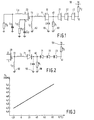
- the device according to FIG. 1 shows the oscillating transistor 20, the gate 72 of which is connected on the one hand to the first self L, and on the other hand to the second self L 2 , the other end of which is connected to the ground 60.
- the gate 71 of the compensating field effect transistor (TEC) 10 is connected to the other end of the inductor L, while the drain and the source of the TEC 10 short-circuited and numbered 40 are connected on the one hand to a resistor R, the other end of which is at ground 60, and on the other hand to the set of 3 TECs, numbered 21, 22 and 23 operating as diodes (drain and short-circuited sources) connected in series (connection drain-source connected to the grid of the following), the first drain-source connection of TEC 21 being connected to point 40 and the last grid of TEC 23 being connected to the end 41 of a resistor R 2 , the other end of which is connected to the DC power supply 50.
- TEC compensating field effect transistor
- the inductors L, and L 2 and the gate-channel capacitance of the TEC 10 constitute the circuit which determines the oscillation frequency of the oscillating transistor 20.
- the circuit consisting of a choke L 12 and a resistor R 12 , as well as a capacitor C 12 in parallel with L 12 and R 12 and mounted between the ground and the source of the oscillating transistor 20 is intended to maintain the oscillation conditions.
- the circuit consisting of a capacitor C 11 and a choke L 11 , mounted between the ground and the drain of the oscillating transistor 20 forms the impedance matching which makes it possible to optimize the output power of the oscillator, the resistance R "placed between ground and the point common to L 11 and C 11 being the load impedance.
- the present invention does not relate to the oscillator itself, but rather, to the circuit forming a variable capacity linearly as a function of the temperature and to the association of such a circuit with the microwave oscillator so to obtain an oscillator both stabilized in frequency as a function of temperature and monolithically integrable on gallium arsenide for example.
- FIG. 2 shows the same circuit in which Schottky diodes replace TECs.
- the operation of the circuit according to FIG. 1 or according to FIG. 2 is based on the fact that it appears in one or the other in microwave, and only in microwave, a capacitance of large value C between the output electrodes 40 of the active element 10 and the earth 60.
- the TEC 10 In direct current, the TEC 10 is isolated.
- the continuous polarization of the TEC channel 10 at point 40 is controlled by the TEC network or by diodes 21, 22, 23 so as to "vary this grid-channel capacity by a desired quantity.
- the resistors Ri and R 2 are used to fix this point of polarization at a reference value for a given temperature.
- the threshold voltage of the TECs or of the diodes 21, 22, 23 varies as a function of the temperature by following a known linear law. It decreases linearly by 2 mV / ° C for a constant current and per Schottky element.
- the applied voltage V v at point 40 varying linearly as a function of temperature, therefore makes it possible to obtain a linear variation in the gate-channel capacitance of transistor 10, which provides excellent frequency compensation for the oscillator, for a frequency of 12 GHz, at temperatures between -20 and + 80 ° C.
- the Schottky TECs or the Schottky diodes are perfectly integrable on an AsGa substrate, as are the resistors which are produced by implantation of a resistive layer in the substrate.
- the inductors L, and L 2 can be integrated in the form of microstrip lines in the form of spirals, and the fixed capacities in the form of interdigitated structure.
Landscapes
- Inductance-Capacitance Distribution Constants And Capacitance-Resistance Oscillators (AREA)
Claims (6)
Applications Claiming Priority (2)
| Application Number | Priority Date | Filing Date | Title |
|---|---|---|---|
| FR8309071A FR2547136B1 (fr) | 1983-06-01 | 1983-06-01 | Circuit de stabilisation de la frequence d'un oscillateur libre en fonction de la temperature |
| FR8309071 | 1983-06-01 |
Publications (2)
| Publication Number | Publication Date |
|---|---|
| EP0128612A1 EP0128612A1 (de) | 1984-12-19 |
| EP0128612B1 true EP0128612B1 (de) | 1987-01-07 |
Family
ID=9289382
Family Applications (1)
| Application Number | Title | Priority Date | Filing Date |
|---|---|---|---|
| EP84200761A Expired EP0128612B1 (de) | 1983-06-01 | 1984-05-25 | Schaltung mit einer temperatur-variablen Kapazität und frequenzstabilisierter Hyperfrequenzoszillator mit einer solchen Schaltung |
Country Status (5)
| Country | Link |
|---|---|
| US (1) | US4599581A (de) |
| EP (1) | EP0128612B1 (de) |
| JP (1) | JPS6035805A (de) |
| DE (1) | DE3461975D1 (de) |
| FR (1) | FR2547136B1 (de) |
Families Citing this family (4)
| Publication number | Priority date | Publication date | Assignee | Title |
|---|---|---|---|---|
| US5517053A (en) * | 1995-01-09 | 1996-05-14 | Northrop Grumman Corporation | Self stabilizing heater controlled oscillating transistor |
| US6201287B1 (en) | 1998-10-26 | 2001-03-13 | Micron Technology, Inc. | Monolithic inductance-enhancing integrated circuits, complementary metal oxide semiconductor (CMOS) inductance-enhancing integrated circuits, inductor assemblies, and inductance-multiplying methods |
| US6249191B1 (en) * | 1998-11-23 | 2001-06-19 | Micron Technology, Inc. | Monolithic integrated circuit oscillators, complementary metal oxide semiconductor (CMOS) voltage-controlled oscillators, integrated circuit oscillators, oscillator-forming methods, and oscillation methods |
| FR2949612A1 (fr) * | 2009-08-28 | 2011-03-04 | Thomson Licensing | Systeme d'antenne comprenant une antenne electriquement petite pour reception de signaux de canaux de la bande uhf |
Family Cites Families (10)
| Publication number | Priority date | Publication date | Assignee | Title |
|---|---|---|---|---|
| FR1352257A (fr) * | 1963-01-04 | 1964-02-14 | Csf | Dispositif de compensation de dérive thermique applicable notamment aux oscillateurs à quartz |
| US3697890A (en) * | 1969-06-09 | 1972-10-10 | Us Navy | Wide deviation voltage controlled crystal oscillator with temperature compensation |
| JPS4854850A (de) * | 1971-11-09 | 1973-08-01 | ||
| FR2241778B1 (de) * | 1973-07-13 | 1977-09-09 | Thomson Csf | |
| US4015219A (en) * | 1974-01-16 | 1977-03-29 | Hitachi, Ltd. | Electronic circuit using field effect transistor with compensation means |
| US4187476A (en) * | 1977-01-31 | 1980-02-05 | Hitachi, Ltd. | SHF band oscillator circuit using FET |
| JPS5564405A (en) * | 1978-11-08 | 1980-05-15 | Seiko Instr & Electronics Ltd | Receiver circuit with temperature compensating function |
| JPS5579506A (en) * | 1978-12-11 | 1980-06-16 | Mitsubishi Electric Corp | Oscillator |
| DE2945546C2 (de) * | 1979-11-10 | 1983-09-29 | Philips Patentverwaltung Gmbh, 2000 Hamburg | Schaltungsanordnung für abstimmbare HF-Kreise |
| US4333062A (en) * | 1979-12-27 | 1982-06-01 | Matsushita Electric Industrial Co., Ltd. | Temperature stabilized MIC solid-state oscillator |
-
1983
- 1983-06-01 FR FR8309071A patent/FR2547136B1/fr not_active Expired
-
1984
- 1984-05-25 DE DE8484200761T patent/DE3461975D1/de not_active Expired
- 1984-05-25 EP EP84200761A patent/EP0128612B1/de not_active Expired
- 1984-05-25 US US06/614,186 patent/US4599581A/en not_active Expired - Fee Related
- 1984-05-31 JP JP59109765A patent/JPS6035805A/ja active Pending
Also Published As
| Publication number | Publication date |
|---|---|
| DE3461975D1 (en) | 1987-02-12 |
| FR2547136A1 (fr) | 1984-12-07 |
| EP0128612A1 (de) | 1984-12-19 |
| US4599581A (en) | 1986-07-08 |
| FR2547136B1 (fr) | 1985-07-12 |
| JPS6035805A (ja) | 1985-02-23 |
Similar Documents
| Publication | Publication Date | Title |
|---|---|---|
| EP1424776B1 (de) | Spannungsgesteuerte Oszillatorschaltung für eine elektronische Vorrichtung mit niedriger Leistung | |
| EP0256580A1 (de) | Gyratorschaltung, die eine Induktanz simuliert | |
| EP0060165B1 (de) | In Frequenz gesteuerter Oszillator mit einem piezoelektrischen Element und der ein gedehntes Frequenzänderungsgebiet hat | |
| US6417740B1 (en) | Wide-band/multi-band voltage controlled oscillator | |
| FR2840470A1 (fr) | Circuit a boucle a phase asservie et dispositif semiconducteur a circuit integre | |
| EP3416284B1 (de) | Architektur mit spannungsaufteilung zwischen zwei oszillatoren | |
| FR3035285A1 (fr) | Circuit d'amplification de puissance de signaux radiofrequence | |
| FR2546686A1 (fr) | Circuit oscillant a frequence variable se presentant sous forme d'un circuit integre | |
| FR2498843A1 (fr) | Dispositif oscillateur-melangeur stabilise par un resonateur dielectrique | |
| FR3017995A1 (fr) | Dispositif electronique a transistor hemt polarise en inverse | |
| US7068115B2 (en) | Monolithic microwave integrated circuit voltage controlled coupled feedback oscillator | |
| EP0128612A1 (de) | Schaltung mit einer temperatur-variablen Kapazität und frequenzstabilisierter Hyperfrequenzoszillator mit einer solchen Schaltung | |
| FR2644647A1 (fr) | Oscillateur hyperfrequence commande en tension | |
| FR2833432A1 (fr) | Dispositif de compensation en temperature et appareil electronique comprenant un tel dispositif | |
| EP0203663B1 (de) | Hyperfrequenzleistungsoszillator, der in einem grossen Frequenzgebiet linear moduliert ist | |
| EP3891877A1 (de) | Klasse-phi-2 -leistungswandler mit selbstschwingender schaltersteuerschaltung | |
| FR2580125A1 (de) | ||
| EP0387746A1 (de) | Transistoroszillator für höhere Frequenzen | |
| EP0372643B1 (de) | Integrierte Halbleiterschaltung mit einer Leistungsverstärkerstufe für Ultrahochfrequenz | |
| FR2544929A1 (fr) | Oscillateur a quartz a faible bruit | |
| EP0762259B1 (de) | Vorspannungsschaltung zur Stellung des durchschnittlichen Pegels einer alternierenden Spannung | |
| FR2561048A1 (fr) | Oscillateur hyperfrequences a transistor, commande par capacite variable | |
| FR2756987A1 (fr) | Circuit oscillant | |
| FR2586872A1 (fr) | Convertisseur hyperfrequence-radiofrequence monolithique. | |
| EP0267332A1 (de) | Direkt frequenzmodulierter, kristallgesteuerter Oszillator |
Legal Events
| Date | Code | Title | Description |
|---|---|---|---|
| PUAI | Public reference made under article 153(3) epc to a published international application that has entered the european phase |
Free format text: ORIGINAL CODE: 0009012 |
|
| AK | Designated contracting states |
Designated state(s): DE FR GB IT |
|
| 17P | Request for examination filed |
Effective date: 19850311 |
|
| 17Q | First examination report despatched |
Effective date: 19860227 |
|
| GRAA | (expected) grant |
Free format text: ORIGINAL CODE: 0009210 |
|
| AK | Designated contracting states |
Kind code of ref document: B1 Designated state(s): DE FR GB IT |
|
| REF | Corresponds to: |
Ref document number: 3461975 Country of ref document: DE Date of ref document: 19870212 |
|
| ITF | It: translation for a ep patent filed | ||
| PLBE | No opposition filed within time limit |
Free format text: ORIGINAL CODE: 0009261 |
|
| STAA | Information on the status of an ep patent application or granted ep patent |
Free format text: STATUS: NO OPPOSITION FILED WITHIN TIME LIMIT |
|
| 26N | No opposition filed | ||
| REG | Reference to a national code |
Ref country code: FR Ref legal event code: CD |
|
| PGFP | Annual fee paid to national office [announced via postgrant information from national office to epo] |
Ref country code: GB Payment date: 19920430 Year of fee payment: 9 |
|
| PGFP | Annual fee paid to national office [announced via postgrant information from national office to epo] |
Ref country code: FR Payment date: 19920519 Year of fee payment: 9 |
|
| ITTA | It: last paid annual fee | ||
| PGFP | Annual fee paid to national office [announced via postgrant information from national office to epo] |
Ref country code: DE Payment date: 19920724 Year of fee payment: 9 |
|
| PG25 | Lapsed in a contracting state [announced via postgrant information from national office to epo] |
Ref country code: GB Effective date: 19930525 |
|
| GBPC | Gb: european patent ceased through non-payment of renewal fee |
Effective date: 19930525 |
|
| PG25 | Lapsed in a contracting state [announced via postgrant information from national office to epo] |
Ref country code: FR Effective date: 19940131 |
|
| PG25 | Lapsed in a contracting state [announced via postgrant information from national office to epo] |
Ref country code: DE Effective date: 19940201 |
|
| REG | Reference to a national code |
Ref country code: FR Ref legal event code: ST |