EP0128735A2 - Halterungsvorrichtung für zwei Positionen für Zusatzlinsen an Brillen - Google Patents
Halterungsvorrichtung für zwei Positionen für Zusatzlinsen an Brillen Download PDFInfo
- Publication number
- EP0128735A2 EP0128735A2 EP84303790A EP84303790A EP0128735A2 EP 0128735 A2 EP0128735 A2 EP 0128735A2 EP 84303790 A EP84303790 A EP 84303790A EP 84303790 A EP84303790 A EP 84303790A EP 0128735 A2 EP0128735 A2 EP 0128735A2
- Authority
- EP
- European Patent Office
- Prior art keywords
- clip
- head section
- legs
- mounting portion
- hinge
- Prior art date
- Legal status (The legal status is an assumption and is not a legal conclusion. Google has not performed a legal analysis and makes no representation as to the accuracy of the status listed.)
- Withdrawn
Links
Images


Classifications
-
- G—PHYSICS
- G02—OPTICS
- G02C—SPECTACLES; SUNGLASSES OR GOGGLES INSOFAR AS THEY HAVE THE SAME FEATURES AS SPECTACLES; CONTACT LENSES
- G02C9/00—Attaching auxiliary optical parts
- G02C9/04—Attaching auxiliary optical parts by fitting over or clamping on
-
- G—PHYSICS
- G02—OPTICS
- G02C—SPECTACLES; SUNGLASSES OR GOGGLES INSOFAR AS THEY HAVE THE SAME FEATURES AS SPECTACLES; CONTACT LENSES
- G02C9/00—Attaching auxiliary optical parts
- G02C9/02—Attaching auxiliary optical parts by hinging
Definitions
- This invention relates to spectacle accessories and more particularly, it concerns improvements in hinged clip devices by which an auxiliary lens assembly represented by sunglasses, for example, may be clipped to the spectacles for movement between a covering position overlying the lenses of the spectacles and a cleared position in which the auxiliary lenses are retained in a position of noninterference with normal use of the spectacles.
- Auxiliary lens attachments for spectacles are commonly embodied as sunglasses adapted to be releasably mounted or clipped to the frame or lenses of the spectacles.
- the mount for the auxiliary lenses may be a simple clip arrangement by which the auxiliary lenses are removably retained in a single covering position over the spectacle lenses, it is preferable that the mount incorporate a hinge feature by which the auxiliary lenses may be moved between and retained in either a covering position overlying the spectacle lenses or a cleared position, all without physically removing the auxiliary lens unit from the spectacles.
- U.S.-A-3,575,497 discloses an auxiliary lens mounting device representative of the latter class of mounts in which the auxiliary lenses or sunglasses may be adjusted between covering and cleared positions.
- Functional components of such devices include a clip for retention of the device on the spectacle frame or lenses, an auxiliary lens mount, a hinge for interconnecting the lens mount with the clip and some form of yieldable retention means by which the auxiliary lenses are held releasably in either a covering position overlying the spectacle lenses or a cleared position in which the auxiliary lenses are retained in the cleared position.
- a spectacle mounting device comprises: a clip portion for removably securing the device to spectacles, a hinge portion, and a mounting portion adapted to receive auxiliary lenses and connected to the clip portion by the hinge portion for movement between a covering position in which auxiliary lenses attached to the mounting portion overlie spectacle lenses to which the mounting device is attached and a cleared position in which the auxiliary lenses attached to the mounting portion are out of the normal field of vision through the spectacle lenses; and is characterized in that the clip portion, the hinge portion and the mounting portion are formed by a one-piece moulding of plastics material and in that the hinge portion includes over-centring spring means for advancing the mounting portion to and retaining the mounting portion in either of the covering and cleared positions.
- Such a one-piece two-position mounting device for attaching auxiliary lenses to spectacles can be manufactured at lower cost than the prior assemblies of discrete components.
- the clip portion of the device preferably includes front and rear pairs of clasping clip legs depending from a block-like head section in a manner such that one of the two pairs is resilient in relation to the other.
- the one leg thus provides a clasping bias while the other leg pair establishes a reference bearing against one side of the spectacle frame and/or lenses over which the clip portion is received.
- the auxiliary lens mounting portion is interconnected with the head section of the clip portion by the hinge portion which preferably includes a spring component of the same plastic material to be operative as an overcentring spring device to urge the mounting portion in either the cleared position or the covering position in relation to the spectacle lenses.
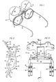
- the mounting device is generally designated by the reference numeral 10 and shown as it is used to support an auxiliary lens unit 12 from the bridge area of a pair of spectacle lenses 14 typically mounted in a frame 16 to which ear pieces 18 are attached.
- the auxiliary lens unit 12 is a single sheet of form-sustaining plastic material shaped to provide a pair of auxiliary lens portions 20 separated by a bridge portion 22.
- the unit 12 is shown in a cleared position in which the field of view through the spectacle lenses 14 is unobstructed by the auxiliary unit 12. As will be apparent from the description to follow of the mounting device 10, the unit 12 is movable from the cleared position shown in Fig.
- the sheet defining the lenses 20 may be shaded and polarizing to function as sunglasses and thus protect the user of the spectacles from bright light and glares.
- the auxiliary lens unit 12 may also serve as a protective barrier against objects or materials which may damage or impair vision through the spectacle lenses 14.
- the mounting device 10 of the invention is a one-piece molding of suitable plastic material such as polypropylene.
- suitable plastic material such as polypropylene.
- the structure of the device 10 entails an integral organization of interconnected portions which serve as components having dimensional criteria related primarily to the plastic material in a way to be determinative of such relative physical characteristics as flexure, resiliency and rigidity.
- the composite illustrations in Figs. 2-11 will deserve careful scrutiny in the interest of gaining a complete understanding of the structure and functional or operational features embodied in the mounting device 10.
- the mounting device 10 may be characterized as having three major portions which are apparent in Figs. 2-6 and 8 as a clip portion 26, a hinge portion 28 and an auxiliary lens mounting portion 30.
- the clip portion 26 is defined by a head section 32 from which clip legs depend as front and rear pairs 34 and 36,_ respectively.
- the head section 32 is in the nature of a block-like formation having an upwardly and forwardly oriented recess 38 (Fig. 5). In the plan view of Fig. 7, it will be observed that the head section 32 is located centrally across the width of the device 10, assuming about one-third of the transverse dimension or width of the device 10.
- the front pair of clip legs 34 depend from the ends of a relatively heavy and thus rigid beam section 40 joining with the front of the head section 32.
- the front legs 34 are also relatively heavy and thus rigid and are shaped to define an upper forwardly facing, generally flat surface 41 and a convex spectacle lens engaging surface 42 as a result of an arcuate configuration terminating in a downwardly and forwardly projecting distal end 44.
- the lateral spacing between the front clip legs 34 is less than the lateral spacing of the rear clip legs 36.
- the rear clip legs 36 are supported at their upper ends from a flange portion 46 which depends from the head section 32 as may be observed most clearly from Figs. 4 and 5.
- the connection of the flange 46 to the rear of the head section 32 is delimited in length by a pair of slots 48 which space opposite ends of the head section 32 from the inboard sides of a pair of forwardly projecting rear clip leg spreading tabs 50.
- the tabs 50 are serrated on their upper surfaces as may be observed in Figs. 4 and 5 and in their upward and forward projection from the flange 46 become spaced at their front ends from the top of the beam section 40 carrying the front clip legs 34. This latter relationship is shown most clearly in Figs. 2 and 3.
- the configuration of the rear clip legs 36 in a normal or a relaxed condition of the device 10 is as shown in solid lines in Figs. 2, 5 and 8 of the drawings.
- the legs are reversely curved to provide a forwardly facing convex bearing surface 52 merging with a downwardly and rearwardly projecting distal end 54.
- the respective ends 44 and 54 of the front and rear legs 34 and 36 define approximately a right angle with each other as shown. This diverging relationship of the leg ends 44 and 54 facilitate mounting the device 10 on the spectacle lenses 14.
- the tabs 50 are depressed and because of the limited length connection of the flange 46 to the head section 32, the rear legs 36 flex generally about the axis 55 (Fig. 4) to the approximate position illustrated by phantom lines in Fig. 5 of the drawings. In this condition, the clip portion 26 may be depressed downwardly over the lenses 14 to assume the approximate final position illustrated in Fig. 6 of the drawings.
- the relatively rigid connection of the front clip legs 34 to the head section 32 causes the front legs 32 to be determinative of the positioning of the clip portion 26 on the spectacle lenses 14.
- the relatively flexible connection of the rear legs 36 allows the rear clip legs to be flexed to a relatively open condition for clasping engagement with the spectacle lenses 14 and yet exert a relatively strong spring or clasping force against the front and rear surfaces of the spectacle lenses 14 at the bearing surfaces 42 and 52 of the clip legs 34 and 36.
- the auxiliary lens mounting portion 30, as shown in Fig. 4, includes a plate-like portion 56 of the device 10. Although the major peripheral configuration of the plate 56 is predicated in substantial measure on aesthetics, it functions to attach the auxiliary lens unit 12 with the device 10 with staking tenons 58 projecting from the outer surface 60 of the plate 56. Although the tenons 58 are illustrated as cylindrical posts in Figs. 2-4, for example, these tenons extend through apertures in the auxiliary lens unit 12 and are thereafter fused over the outer surface of the auxiliary lens unit 12 as an enlarged head in the manner of a rivet.
- the hinge portion 28 serves to interconnect the lens mounting portion 30 and the clip portion 26. More specifically, the structure of the hinge unit, as shown most clearly in Figs. 2-4 of the drawings, includes a pair of L-shaped extensions 62 of the plate-like portion 56. A relatively long leg of each extension 62 lies in the plane of the plate portion 56, whereas a relatively short leg portion 64 of each extension 62 terminates in a flexure hinge 66. As shown most clearly in Figs. 2, 5 and 10, the flexure hinge 66 joins with the head section 32 near the front surface 68 thereof.
- a V-shaped spring section 70 Positioned between the extensions 62 is a V-shaped spring section 70 having one leg 72 extending from a common juncture 74 to a flexure hinge 76.
- the other leg 78 of the spring 70 extends from the juncture 74 to another flexure hinge 80 joining with the head section 32 of the clip portion 26 near the rear surface 82 thereof.
- the legs 72 and 78 thereof establish an acute angle of approximately 60 degrees.
- the spring 70 is selected to be of a thickness of the plastic material from which the device 10 is molded which when coupled with its width (Figs. 3, 4 and 7) will exhibit a spring-like characteristic as a result of resiliency in the legs 72 and 78 and particularly at the juncture 74 of the two legs.
- the effect of the spring 70 in the device 10 may be appreciated from the illustration in Fig. 6 of the drawings where the respective flexure hinges 66, 76 and 80 are represented in point form.
- Fig. 6 the respective flexure hinges 66, 76 and 80 are represented in point form.
- the point of the hinge 76 as a result of pivotal movement of the mounting plate 56 about the hinge pivot 66, follows an arcuate path represented by the dashed arc 82 from the cleared position represented in phantom lines to a covering position represented in solid lines.
- the point 76 is carried through the arc 82, causing the spring 70 to flex or exhibit a tension force between the hinge points 76 and 80.
- the point 76 passes over a top- dead-center position represented by the axis or line 86 approximately midway between the cleared and covering positions.
- the spring snaps the mounting plate and the auxiliary lens unit 12 to either one of the cleared or covering positions.
- the arm 78 of the spring 70 lies within the recess 38 in the head section 32.
- the mounting plate portion 56 is biased against the front upper surface 41 of the front clip legs in a way to positively position the auxiliary lens unit 12 in relation to the spectacle lenses 14.
- the covering position may be characterized as that position in which the mounting portion 30 is folded against the clip portion 26.
- the cleared position may be considered as that position in which the mounting portion 30 extends clear of or away from the clip portion 26.
- the manufacture thereof facilitates use of injection molding techniques and a substantial reduction in cost in relation to prior art devices requiring assembly of discrete components.
- the device is a fully operational, two-position auxiliary lens mount exhibiting features including ease of attachment to and removal from a pair of spectacles, firmness of mounting to the spectacles with positional accuracy, positive retention of the auxiliary lenses in either covering or cleared positions, and spring assisted movement of the auxiliary lenses to both of the two positions.
Landscapes
- Physics & Mathematics (AREA)
- Health & Medical Sciences (AREA)
- General Physics & Mathematics (AREA)
- Ophthalmology & Optometry (AREA)
- Optics & Photonics (AREA)
- Eyeglasses (AREA)
Applications Claiming Priority (2)
| Application Number | Priority Date | Filing Date | Title |
|---|---|---|---|
| US50248283A | 1983-06-09 | 1983-06-09 | |
| US502482 | 1983-06-09 |
Publications (2)
| Publication Number | Publication Date |
|---|---|
| EP0128735A2 true EP0128735A2 (de) | 1984-12-19 |
| EP0128735A3 EP0128735A3 (de) | 1986-05-14 |
Family
ID=23998039
Family Applications (1)
| Application Number | Title | Priority Date | Filing Date |
|---|---|---|---|
| EP84303790A Withdrawn EP0128735A3 (de) | 1983-06-09 | 1984-06-05 | Halterungsvorrichtung für zwei Positionen für Zusatzlinsen an Brillen |
Country Status (3)
| Country | Link |
|---|---|
| EP (1) | EP0128735A3 (de) |
| JP (1) | JPS608819A (de) |
| DE (1) | DE128735T1 (de) |
Cited By (6)
| Publication number | Priority date | Publication date | Assignee | Title |
|---|---|---|---|---|
| EP0238479A3 (de) * | 1986-03-21 | 1989-08-30 | Polaroid Corporation | Klappbares optisches Teil zur Verwendung mit Brillen |
| GB2251702A (en) * | 1990-11-29 | 1992-07-15 | Derek Glick | Spectacles attachment |
| DE4214413A1 (de) * | 1992-05-05 | 1993-11-11 | Hafner Klaus | Vorhängebrille |
| FR2741164A1 (fr) * | 1995-11-09 | 1997-05-16 | Buffard Denis | Articulation pour lunettes assurant une liaison pivotante et amovible entre une monture principale et une monture secondaire desdites lunettes et lunettes munies d'une telle articulation |
| FR2830947A1 (fr) * | 2001-10-17 | 2003-04-18 | Locaplast | Lunettes, notamment pour la peche |
| CN106999300A (zh) * | 2014-10-23 | 2017-08-01 | Tidi制品公司 | 用于防护眼镜的系统和方法 |
Families Citing this family (2)
| Publication number | Priority date | Publication date | Assignee | Title |
|---|---|---|---|---|
| JPH0687926U (ja) * | 1993-05-31 | 1994-12-22 | 倉澤光学工業株式会社 | 屈折度補正用眼鏡 |
| JP7109052B2 (ja) * | 2018-04-10 | 2022-07-29 | 株式会社ナイツ | 双眼ルーペおよび双眼ルーペ装置 |
Family Cites Families (3)
| Publication number | Priority date | Publication date | Assignee | Title |
|---|---|---|---|---|
| US2737848A (en) * | 1954-07-22 | 1956-03-13 | Foster Grant Co Inc | Clip-on sunglass |
| US3575497A (en) * | 1969-08-11 | 1971-04-20 | Foster Grant Co Inc | Auxiliary eye protection assembly |
| FR2449901A1 (fr) * | 1979-02-23 | 1980-09-19 | Essilor Int | Support pour face de monture de lunettes, en particulier pour emploi sous casque |
-
1984
- 1984-06-05 DE DE1984303790 patent/DE128735T1/de active Pending
- 1984-06-05 JP JP11400684A patent/JPS608819A/ja active Pending
- 1984-06-05 EP EP84303790A patent/EP0128735A3/de not_active Withdrawn
Cited By (9)
| Publication number | Priority date | Publication date | Assignee | Title |
|---|---|---|---|---|
| EP0238479A3 (de) * | 1986-03-21 | 1989-08-30 | Polaroid Corporation | Klappbares optisches Teil zur Verwendung mit Brillen |
| GB2251702A (en) * | 1990-11-29 | 1992-07-15 | Derek Glick | Spectacles attachment |
| DE4214413A1 (de) * | 1992-05-05 | 1993-11-11 | Hafner Klaus | Vorhängebrille |
| FR2741164A1 (fr) * | 1995-11-09 | 1997-05-16 | Buffard Denis | Articulation pour lunettes assurant une liaison pivotante et amovible entre une monture principale et une monture secondaire desdites lunettes et lunettes munies d'une telle articulation |
| FR2830947A1 (fr) * | 2001-10-17 | 2003-04-18 | Locaplast | Lunettes, notamment pour la peche |
| EP1408363A1 (de) * | 2001-10-17 | 2004-04-14 | Locaplast | Insbesondere zum Angeln verwendbare Brille |
| CN106999300A (zh) * | 2014-10-23 | 2017-08-01 | Tidi制品公司 | 用于防护眼镜的系统和方法 |
| EP3209255A4 (de) * | 2014-10-23 | 2018-06-27 | Tidi Products, LLC | System und verfahren für schutzbrille |
| US10517763B2 (en) | 2014-10-23 | 2019-12-31 | Tidi Products, Llc | System and method for protective eyewear |
Also Published As
| Publication number | Publication date |
|---|---|
| DE128735T1 (de) | 1986-10-16 |
| EP0128735A3 (de) | 1986-05-14 |
| JPS608819A (ja) | 1985-01-17 |
Similar Documents
| Publication | Publication Date | Title |
|---|---|---|
| US3575497A (en) | Auxiliary eye protection assembly | |
| US5321443A (en) | Removable sunglass assembly for attachment to a conventional eyeglass assembly | |
| US4345824A (en) | Eyeglass frames openable at the bridge | |
| US5052054A (en) | Cap structure with implement adapter | |
| US5005263A (en) | Eyeglass support | |
| JPH0725172Y2 (ja) | かみそり刃組立体 | |
| US6659605B2 (en) | Clip-on eyewear | |
| US4659196A (en) | Optical accessory for use with spectacles | |
| KR100530416B1 (ko) | 안경 | |
| US3413057A (en) | Spectacle supported pivoted auxiliary eye protectors | |
| EP0128735A2 (de) | Halterungsvorrichtung für zwei Positionen für Zusatzlinsen an Brillen | |
| CA1290964C (en) | Pivoting optical accessory for use with spectacles | |
| EP0928582A2 (de) | Befestigungsvorrichtung eines Sitzlehnentablettes | |
| US5258786A (en) | Attachable pivotal visor | |
| FR2706637A1 (fr) | Monture de lunettes. | |
| JPH08160363A (ja) | 折畳み眼鏡 | |
| US5106178A (en) | Prescription lens holder for use with sunglasses | |
| US6254232B1 (en) | Spring clip for mounting sunglasses | |
| JP2001305493A (ja) | 前掛け眼鏡及びそれを眼鏡本体に取り付けるための取り付け方法 | |
| GB2352830A (en) | One piece plastics spectacle frame | |
| US20050078270A1 (en) | Arrangement for securing sunglasses to eyeglasses | |
| US2825066A (en) | Eye shade for glasses | |
| US4527860A (en) | Antiglare rear view mirror | |
| JP2875485B2 (ja) | ゴーグル | |
| JPS6220528B2 (de) |
Legal Events
| Date | Code | Title | Description |
|---|---|---|---|
| PUAI | Public reference made under article 153(3) epc to a published international application that has entered the european phase |
Free format text: ORIGINAL CODE: 0009012 |
|
| AK | Designated contracting states |
Designated state(s): AT CH DE FR GB IT LI NL |
|
| PUAL | Search report despatched |
Free format text: ORIGINAL CODE: 0009013 |
|
| AK | Designated contracting states |
Kind code of ref document: A3 Designated state(s): AT CH DE FR GB IT LI NL |
|
| TCAT | At: translation of patent claims filed | ||
| TCNL | Nl: translation of patent claims filed | ||
| ITCL | It: translation for ep claims filed |
Representative=s name: RICCARDI SERGIO & CO. |
|
| DET | De: translation of patent claims | ||
| EL | Fr: translation of claims filed | ||
| 17P | Request for examination filed |
Effective date: 19861024 |
|
| 17Q | First examination report despatched |
Effective date: 19871001 |
|
| STAA | Information on the status of an ep patent application or granted ep patent |
Free format text: STATUS: THE APPLICATION IS DEEMED TO BE WITHDRAWN |
|
| 18D | Application deemed to be withdrawn |
Effective date: 19880412 |
|
| RIN1 | Information on inventor provided before grant (corrected) |
Inventor name: MALERBI, ROBERT A. Inventor name: LANE, WILLIAM P. |