EP0128746A2 - Hochbelastbares Gleitlager mit einem hydrostatisch abgestützten Kippsegment - Google Patents
Hochbelastbares Gleitlager mit einem hydrostatisch abgestützten Kippsegment Download PDFInfo
- Publication number
- EP0128746A2 EP0128746A2 EP84303854A EP84303854A EP0128746A2 EP 0128746 A2 EP0128746 A2 EP 0128746A2 EP 84303854 A EP84303854 A EP 84303854A EP 84303854 A EP84303854 A EP 84303854A EP 0128746 A2 EP0128746 A2 EP 0128746A2
- Authority
- EP
- European Patent Office
- Prior art keywords
- pad
- film
- hydrostatic
- wedge
- pivoted
- Prior art date
- Legal status (The legal status is an assumption and is not a legal conclusion. Google has not performed a legal analysis and makes no representation as to the accuracy of the status listed.)
- Withdrawn
Links
Images


Classifications
-
- F—MECHANICAL ENGINEERING; LIGHTING; HEATING; WEAPONS; BLASTING
- F16—ENGINEERING ELEMENTS AND UNITS; GENERAL MEASURES FOR PRODUCING AND MAINTAINING EFFECTIVE FUNCTIONING OF MACHINES OR INSTALLATIONS; THERMAL INSULATION IN GENERAL
- F16C—SHAFTS; FLEXIBLE SHAFTS; ELEMENTS OR CRANKSHAFT MECHANISMS; ROTARY BODIES OTHER THAN GEARING ELEMENTS; BEARINGS
- F16C9/00—Bearings for crankshafts or connecting-rods; Attachment of connecting-rods
- F16C9/04—Connecting-rod bearings; Attachments thereof
-
- F—MECHANICAL ENGINEERING; LIGHTING; HEATING; WEAPONS; BLASTING
- F16—ENGINEERING ELEMENTS AND UNITS; GENERAL MEASURES FOR PRODUCING AND MAINTAINING EFFECTIVE FUNCTIONING OF MACHINES OR INSTALLATIONS; THERMAL INSULATION IN GENERAL
- F16C—SHAFTS; FLEXIBLE SHAFTS; ELEMENTS OR CRANKSHAFT MECHANISMS; ROTARY BODIES OTHER THAN GEARING ELEMENTS; BEARINGS
- F16C17/00—Sliding-contact bearings for exclusively rotary movement
- F16C17/02—Sliding-contact bearings for exclusively rotary movement for radial load only
- F16C17/03—Sliding-contact bearings for exclusively rotary movement for radial load only with tiltably-supported segments, e.g. Michell bearings
Definitions
- pivot structure It is the purpose of the present invention to produce a very stiff and very strong pivot structure which permits the pivoted pad slider bearing to be used at extremely high bearing loads. Another purpose is to build a pivoted pad slider bearing that is geometrically compact and inexpensive to mass produce. It is expected that the pivot structure disclosed here will permit Kingsbury-type bearings to be practically applied to the very highly loaded bearings of internal combustion engines, and also to a large number of highly loaded mechanical assemblies.
- the invention is a hydrostatically supported pivoted pad bearing applicable as a journal bearing or as a flat pad for thrust bearing service. Hydrostatically supported pivoted pad bearings per se are not new.
- the pivoted pad bearing of Hollingsworth is described in Patent #4,059,318.
- the Hollingsworth bearing has been successfully used on ships for more than a decade.
- the pivoting pad has a hole communicating between the wedge film and a hydrostatic film side of the pad. This hole feeds oil pressurized by the convergent wedge film to the hydrostatic support geometry floating the pad on a hydrostatic film.
- the pivoting pad of Hollingsworth lacks high load bearing capacity because pressure differentials between the wedge and the hydrostatic side of the pad bend the pad and destroy film stability.
- the pad pivot support of the present invention a large number of holes communicate between the wedge and the hydrostatic side of the pivot.
- the hole geometry is arranged so that differential pressures between corresponding points of the hydrostatic and wedge film surfaces are small. This radically reduces pad bending moments, so that the pad maintains its shape without the large distortions which destroy wedge film stability under heavy loads.
- the pad itself is flexible.
- the pad is restrained (within the limits of a very thin hydrostatic film) by the stiffness of the structure which supports the hydrostatic film.
- This support structure can be very stiff. Because of the increased effective pad stiffness, the pivoted pad arrangement of the present invention can much more closely approximate the theory of an infinitely stiff, infinitely strong pivoted slider. The pad can therefore support much heavier loads than were previously practical.
- Another purpose of the present invention is to eliminate the spragging or binding characteristic of common Kingsbury bearings under start-up conditions.
- pivoted pad slider bearings lubricated with oil are well known.
- Greases have the advantage that they can be packed into the bearing to eliminate the need for continuous lubricant feeds.
- a grease lubricated hydrostatically supported pivoted slider bearing arrangement designed to function as a one-to-one substitution for a roller bearing package is disclosed. Calculations indicate that such a bearing package should have load capacity much larger than that of a roller bearing package of the same size.
- the grease filled hydrostatic bearing should be useful for applications in tooling where centering the journal is important, and should be characterized by effectively infinite fatigue life and low friction.
- Pivoted pad slider bearings can operate efficiently on greases as well as oils.
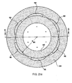
- Figures 21a, 21b and 21c illustrate a grease lubricated pivoted pad slider arrangement designed to substitute for a conventional grease packed roller bearing assembly.
- Figure 21a is a central cross section perpendicular to the journal of the bearing.
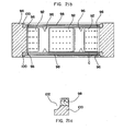
- Figure 21b is a central cross section of the bearing assembly parallel to the journal axis, illustrating pad arrangement, grease seals, and grease feed geometry.
- Figure 21c is an enlarged view on dashed line C-C of 21b illustrating the grease seal and grease distribution groove arrangement in the bearing end packing.
- Figure 1 shows a side view parallel to the journal and wrist pin axes.
- Figure 2 shows a side view of the con rod perpendicular to the journal and wrist pin axes.
- Figure 3 shows a sectional view of Figure I (across the parting line between the con rod and the connecting rod cap).
- a connecting rod having a connecting rod cap and journal bearing structure 7 is equipped with pivoted pad slider bearings rather than the conventional journal arrangement on the compression loaded side of the big end journal bearing.
- Loads on the con rod are (1) direct compression between the center of the wrist pin and the center of the journal due to piston pressure forces, and (2) inertia loads due to the mass of the con rod.
- Pivoted pad 1 bears the direct compression load between wrist pin and journal centers.
- This pad 1 is a thin piece having a journal contacting surface 2b which is cylindrical and of only slightly larger radius of curvature than that of the journal.
- the opposite side of pad 1 is hydrostatic support surface 2a which may be cylindrical.
- Surface 2a is closely matched to a mated surface in con rod 16 to form a hydrostatic support.
- Cylindrical surface 2a floats on a hydrostatic film and is centered on geometrical center point 2c.
- Pad 1 is free to rotate about this virtual center 2c. This rotation orients surface 2b to produce a wedge film in the manner which will be explained and illustrated with respect to Figure 9.
- Smaller pivoted pads 8 and 9 are provided in the con rod to support side forces produced by inertia.
- Figure 3 is a sectional view of Figure 1 showing pad 1 and some other geometrical details of the con rod.
- the wedge film (journal engaging) side 2b of pad 1 is shown, and includes a multiplicity of pressure transfer holes 12. Pressurized oil from these holes feeds hydrostatic surface 2a and maintains a film which separates surface 2a of pad 1 from the corresponding support surface of con rod 16.
- oil reservoir depressions 11 are illustrated in both Figure 1 and Figure 3 . These depression 11 are formed by the clearance between the cylindrical surface which engages surface 2a of pad 1 and the journal (not shown). The clearances are shown by dashed lines in Figure 1. Oil in reservoir depressions 11 should remain when the engine shuts down, and should be particularly useful for start-up lubrication. It should be noted that the bearing arrangement of the con rod shown in Figures 1 - 3 does not restrict oil flow as conventional journal bearings do, so that the oil supply passages in the crankshaft of the engine must be fitted with oil flow restrictors.
- the connecting rod shown in Figures 1 - 3 is intended to operate in a four stroke internal combustion engine.
- the forces between the wrist pin center and journal center go from full compression to full tension every cycle, and the inertial forces on the con rod vary sinusoidally and in proportion to rpm 2 .
- rpm 2 the forces between the wrist pin center and journal center go from full compression to full tension every cycle, and the inertial forces on the con rod vary sinusoidally and in proportion to rpm 2 .
- side forces and tensile forces are small, and the overwhelming bulk of the bearing load is direct compression on pad 1.
- pad 1 Under these low rpm conditions that conventional journal bearings cause trouble and limit engine performance.
- pad 1 Under these low rpm conditions, pad 1 will act as a pivoted pad, but the friction will be somewhat lower than the steady state theoretical value because of squeeze film forces.
- journal bearing performs well at the high rpms where the load on cap 7 is appreciable, so there is no incentive to use a pivoted pad slider to bear tension loads between the wrist pin and journal centers on the con rod. (For an analogous reason, there is an incentive to produce pivoted pads on the main bearing caps which bear compression loads, but not on the portion of the main bearing arc machined directly into the engine block.)
- Figures 4, 5, and 6 show the arrangement and mounting of pad 1 in more detail.
- Figure 4 is an enlarged side cross section view of pad 1.
- Figure 5 is a view of pad 1 on surface 2b, its wedge film (journal contacting) side.
- Figure 6 is a view of pad 1 on surface 2a, the hydrostatically supported side.
- Figure 6 shows an arrangement of pressure distribution relief patches 14 which distribute pressurized oil from holes 12 to larger areas of the hydrostatic pad.
- the hole and patch pattern produces hydrostatic pad lift-off and distributes pressure in the hydrostatic film between surface 2a and the corresponding closely matched surface in its receiver (in the case of Figure 1, the con rod).
- Relief patches 14 are deep enough that they are negligibly restrictive compared to the restriction of the oil film between surface 2a and its corresponding receiver surface.
- the pressure anywhere on a distribution patch 14 corresponds to the pressure in the corresponding hole 12.
- Each hole 12 picks up oil at the pressure corresponding to a particular area on the wedge film and supplies oil at this pressure (minus any losses at the entrance of hole 12 on the wedge side) to a particular area on the hydrostatic side of the pad.
- These input pressures from the patches determine the total pressure distribution in the hydrostatic film between surface 2a and the receiver surface.
- the patch and hole distribution is chosen so that the total pressure generated force of the hydrostatic pad just balances the pressure generated force of the wedge film at a thin hydrostatic film thickness.
- the pressure distribution in the hydrostatic film also adjusts itself so as to minimize bending forces and distortions of the pad.
- the arrangement of wedge pressure supply holes 12 and distribution patches 14 should be such that the hydrostatic film pressures more than balance the forces on the wedge film if the hydrostatic film is too thin (generating forces to thicken the hydrostatic film) and so that pressure losses from the wedge film to patches 14 reduce the pressure in the hydrostatic film so that it is insufficient to balance the wedge film forces if the hydrostatic film is too thick.
- the hydrostatic film will equilibrate to a thickness assuring film stability and zero static friction of the pad pivot, but at a film thickness small enough to minimize losses in wedge film load bearing capacity.
- Proper arrangement of pressure supply holes 12 and distribution patches 14 will assure this stability of the hydrostatic film over all conditions of bearing loading and bearing speed, since the shape of the film pressure distribution in a pivoted pad wedge is constant for all speeds and loads.
- the distribution of holes 12 and pressure distribution patches 14 shown in Figures 4, 5, and 6 is illustrative only.
- the pressure distribution of the hydrostatic film can be matched more closely to the pressure distribution in the wedge film as the number of distribution holes 12 are increased.
- the lift-off of the pad is more certain as the area of distribution patches 14 is increased. It can be shown mathematically that an innumerable number of combinations of pressure distribution holes 12 and distribution patches 14 can serve to produce a dynamically stable hydrostatically supported pivot.
- the pad geometry illustrated in Figures 4, 5 and 6 uses distribution patches and parallel holes to secure a stable hydrostatic film on surface 2a.
- Distribution patches analogous to patches 14 are necessary when the pressure distribution holes between the wedge and the hydrostatic side of the pad are parallel. However, the distribution patches are unnecessary if the holes between the wedge film surface 2b and the hydrostatic film surface 2a are drilled at properly chosen angles to each other. This sets up a transfer relation producing enough pressure in the hydrostatic film to secure lift-off.
- the choice between parallel distribution holes with distribution patches or angled distribution holes is a matter of manufacturing convenience.
- a mathematical illustration of a hydrostatic pad support where the transfer holes are drilled at an angle to the pad to secure pad lift-off is shown with respect to Figure 16e.
- FIG. 7 shows the limiting case of a hydrostatic film pressure distribution which eliminates all bending forces on a pad such as pad 1.
- the total integrated film pressure forces balance the total integrated hydrodynamic wedge pressure forces.
- the hydrostatic film pressures also balance the corresponding wedge film pressures on a point-to-point basis. With this pressure distribution there are no net bending moments anywhere on the pad structure.
- the pressure loads of the hydrostatic film are borne by the structure which supports the hydrostatic oil film. This structure can be much stiffer than the pivoting pad itself.
- the effective bending stiffness of the pivoted pad is the bending stiffness of the support structure, and not the much smaller bending stiffness of the pivoting pad itself.
- the ideal pressure distribution illustrated in Figure 7 will never be exactly achievable, but the distribution hole and distribution patch arrangement can be made so that the hydrostatic film pressures closely approximate the ideal pressure distribution.
- distortions of the pad decrease rapidly (at a rate approximately proportional to the fourth power of the number of holes).
- small distortions of the pad tend to push the pressure distribution in the direction of the ideal pressure distribution. This effect increases film stability and acts to moderate pad deformations.
- Figures 8a and 9 show the static forces which pivot the pad until the pad wedge angle establishes a moment balance about the pivot. The figures assume that the pivot operates with zero static friction.
- Figure 8a is a side view of a flat pad, such as might be used on a thrust bearing, showing pivoting forces.
- Figure 9 is a side view of a pad analogous to the journal type pad of Figures 1 - 7 showing pivoting forces.
- a pad 20 has a flat surface 20b which is a wedge film forming surface for an application such as a thrust bearing.
- the pad 20 has a cylindrical surface 20a centered on point C, which is supported on a hydrostatic film (not shown).
- Surface 20a corresponds to a receiver surface in supporting structure 22.
- a load W is shown perpendicular to pad surface 20b at an angle 9 from a radial line through the center of cylindrical surface 20a. Force vector W can be resolved into vector components radial with respect to center C and tangential to surface 20a.
- the tangential force equals W sin 8. This tangential force acts to rotate (pivot) the pad about center C. Any force W on the pad will tend to rotate the pad unless the line of action of W is in line with the radius from point C (so that 9 vanishes). For this to happen on the pivot geometry of Figure 8a, the vector resultant force W must line up a distance X from the left edge of the pad. Point 23 on Figure 8a is the effective pivot point of the pad. Specifically, the pad and pivot structure shown in Figure 8a can be considered as a pivoted pad with pivot position X in the analysis related to Figure 15.
- Figure 8b and related Figures 8c, 8d and 8e illustrate the geometry of Figure 8a interacting with a sliding surface and an oil film to function as a pivoted plane slider bearing.
- a pivoting pad having flat surface 24 pivots around center 25 on a hydrostatically supported pad which is supported by rigid supporting structure 26.
- a flat sliding surface 28 moves rightward at a velocity U with respect to the stationary pad surface 24a.
- Pad 24 tilts so that convergent oil film 27 is formed. This film generates pressures to separate the pad and balance the moments about pad center of rotation 25.
- FIG. 8c A diagram of the pressure distribution generated is shown as 8c. This pressure distribution has its vector resultant centered so that the pad is in equilibrium.
- Figure 8d shows the pressure distribution which would occur if the pad rotated to produce too large a converging angle. The moment imbalance from this pressure distribution would tend to rotate the pad clockwise toward the pressure distribution of 8c.
- Figure 8e shows the pressure distribution which would occur if the convergent angle between pad 24 and surface 28 was too small. In this case also, the deviation of the pad angle from the optimal angle produces a vector resultant force which tends to pivot the pad toward the optimal angle.
- Figure 8a illustrates schematically a conventional pivoted plane pad.
- Pad 30 rests on pivot 32 supported by structure 34 and interacts with moveable surface 36 (which exerts load).
- F friction force
- FIG 8f illustrates schematically a conventional pivoted plane pad.
- Pad 30 rests on pivot 32 supported by structure 34 and interacts with moveable surface 36 (which exerts load).
- F x d This force produces a torque (F x d) on the pad 30.
- This force called the spragging torque, tends to pull the pad up against the surface into an orientation which locks pad 30 against surface 36.
- Figure 9 is a side view of a pad analogous to the journal type pad shown in Figure 1, and illustrates pivoting forces on the pad.
- Pad 40 is supported by supporting structure 42 and freely pivots on hydrostatic film 44.
- Film 44 is cylindrical and is centered on point 48, which is a distance X from point 46 which is the center of the journal contacting or wedge film surface 49.
- a pressure distribution having a vector resultant load W bears on the wedge contacting surface 49.
- the line of action of W passes through the journal center point 46.
- the effective moment of the force W about the virtual pivot point 48 is equal to X W sin 6.
- the tangential force on the pad tending to produce pivoting is: where r h is the radial distance between hydrostatic film surface 44 and point 48.
- Pad 40 can pivot to an optimal convergence angle in a manner precisely analogous to the pivoting which has previously been explained with respect to Figure 8b.
- Figures 10, 11, 12 and 13 show hydrostatic pad geometries which are arranged to adjust for some misalignment between journal bearings (or flat surfaces) and the pivoted pads.
- Figures 10 and 11 illustrate a hydrostatic pad surface which is spherical. The spherical curvature on the hydrostatic pad side permits alignment of the pad to a misaligned journal and is applicable under conditions where there are fully reversing loads so that squeeze film forces prevent yaw instability.
- Pad 50 has hydrostatically supported surface 54 which is spherical with center 52.
- Figure 11 shows a cross section of pad 50 perpendicular to the journal axis to further illustrate the spherical shape of hydrostatic surface 54.
- the shape of hydrostatic surface 54 does not act to align journal contacting surface 56 with the axis of the journal. If the pad were to rotate with respect to the journal, it might bind, possibly with destruction of the bearing and the machine of which it formed a part. This binding due to rotation of the pad with respect to the journal is called yaw instability.
- the squeeze film pressures act to align the pad surface 56 with the journal, since any part of surface 56 which is close to the journal will produce large squeeze film ressures tending to pivot or rotate the pad into alignment.
- the squeeze film effects which occur in this fully reversing load context therefore prevent yaw instability and make the spherical geometry of surface 54 appropriate for service in applications such as automotive main bearing caps. Under the fully reversing conditions the spherical hydrostatic geometry should produce a close approximation of perfect alignment between pad and journal.
- Figure 12 is a side view of a pad analogous to pad 1 but with compound (torroidal) curvature to allow the pad to compensate to some degree for journal misalignment, but to restrain yaw instability under conditions where the pad is loaded continuously.
- Figure 13 is a cross section view of the pad of Figure 12 perpendicular to the journal axis showing the compound curvature required for yaw stabilization.
- a torroidal pivot geometry pad used for thrust bearing service where the wedge contacting surface is flat, can exactly compensate with a torroidally shaped hydrostatic film surface while restraining yaw instability.
- Figures 14 and 15 are taken from "Analysis and Design of Sliding Bearings," by A. A. Raimondi, J. Boyd, and H. N. Kaufman in Standard Handbook of Lubrication Engineering, McGraw-Hill Book Company, 1968, to illustrate the importance of very close geometrical control between the sliding surfaces of a pivoted pad slider. These charts are calculated for the ideal case of a geometrically perfect, infinitely strong and infinitely stiff pad operating with an oil of constant viscosity. The chart indicates that a pivoted pad wedge film can support extremely heavy loads if the effective stiffness and strength of the pad is great enough.
- the pivot structure of the present invention is expected to radically increase permissable bearing loads, and thereby significantly reduce friction levels attainable in practice.
- This heavy load bearing capacity depends on the minimization of pad deformations due to pressure forces. This reduces to the requirement that the absolute difference in hydrostatic film thickness from place to place in the hydrostatic film be minimized, so that the supporting structure (for example, 16 in the con rod of Figure 1) provides the effective structural stiffness of the pad.
- Figures 16a, 16b, 16c, 16d and 16e show schematically the pressure distribution generated on the wedge film and hydrostatic sides of the pivoted pads.
- Figures 16a, 16b and 16c show in two dimensions the argument for numerous holes to minimize pad bending moments and distortions.
- Figure 16d also illustrates the needs for distribution patches analogous to patches 14 on the hydrostatic side of pad 1 in order to produce lift-off for the hydrostatic support film with parallel transfer holes between the wedge film and hydrostatic pad side.
- Figure 16e illustrates how it is possible with transfer holes drilled at properly chosen angles between the wedge film side and hydrostatic film side to secure pad lift-off and a stable hydrostatic film without the need for transfer patches.
- Figures 16a - 16e each show a wedge film, with the wedge film pressure plotted along with the vector resultant W, which shows that the pad has pivoted to balance.
- Convergence angle M is exaggerated for clarity (conventionally the wedge convergence angle will be .001 radians or less).
- the pivoting pad has one transfer hole drilled perpendicular to the wedge film contacting surface of the pad, which is in line with the maximum film pressure point.
- Figure 16a assumes that there is a constant thickness hydrostatic film between the pivoting pad and its supporting structure. The figure shows the case for a thin axial groove which distributes the pressure from the distribution hole axially along the pad so that the projected pressure distribution in the hydrostatic film will be the line segments shown in 16a.
- Figure 16b shows an analogous case, but with three pressure transfer holes.
- the projected pressure distribution on the hydrostatic pad side now more closely approximates the wedge film.
- Figure 16c is analogous again, but in this case has five presssure distribution holes.
- the projection of hydrostatic film pressure more clearly approximates the wedge film pressure. It can be shown mathematically that with additional transfer holes (additional approximating line segments) the area under the wedge curve and the line segment curve approach each other more and more closely.
- Figures 16a, 16b, and 16c show the advantage of increased numbers of transfer holes in pads, but none of the pads illustrated in these figures would generate sufficient hydrostatic film forces to lift the hydrostatic film and freely pivot the pad.
- the hydrostatic film force will always fall short of the wedge film force. If at some instant in time the conditions shown in 16a or 16b or 16c existed, wedge film pressures would thin the hydrostatic film to the point where the hydrostatic film would break down. When the film breaks down, the pad cannot pivot freely.
- Figure 16d shows how distribution patches 70 (which are analogous to distribution patches 14 on the pad 1 shown in Figures 1 - 6) distribute pressure in a manner which will cause and maintain pad lift-off.
- the pressure distribution shown in Figure 16d would cause the hydrostatic film to thicken.
- Figures 16a, 16b, 16c and 16d show cases where the transfer holes are parallel and perpendicular to the wedge film surface of a flat pad. Lifting of the pad can be achieved without transfer patches if the transfer holes are at properly chosen angles to each other. The hole angles must be chosen to transfer pressure from a higher pressure position on the wedge film side of the pad to a lower pressure position on the projected hydrostatic film side.
- the vector resultant force of the wedge film pressure distribution has a specific direction.
- a one-to-one correspondence between points on the pivoted pad's wedge film side and hydrostatic side can be established by connecting points on the two sides by lines parallel to the wedge film pressure vector resultant.
- the transfer hole angle between the wedge film and hydrostatic side of the pad will tend to lift the pad if the transfer hole takes oil from the pickup area on the wedge film side to an output area on the hydrostatic side which corresponds to a lower pressure area on the wedge film side.
- Figure 16e illustrates this, with transfer holes which are perpendicular to the hydrostatic film side so that higher pressure points in the wedge film transfer pressure to lower pressure points on the hydrostatic film side.
- this sort of transfer arrangement with angled holes will produce pad lift-off. In the three dimensional case the situation is more complicated, but an acceptable hole position and angle arrangement can be arrived at using computer computation procedures which will be discussed later.
- the bending moments on the pad will be smaller with the nonparallel hole arrangement than with the parallel hole and transfer patch arrangement, but the difference in bending moments is usually not significant.
- the choice between transfer patches and angled holes and nonparallel holes without transfer patches is a matter of manufacturing convenience. In the case of pivoted pads which function in journal bearings, it is often possible to use the nonparallel hole arrangement where the holes are normal to the journal contacting surface and radial with respect to the journal bearing center. This hole distribution pattern is easy to manufacture.
- Real pivoted pads are three dimensional, and not the idealized two dimensional pads shown in Figures 16a - 16d.
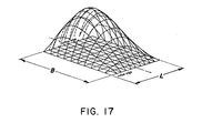
- Figure 17 illustrates the pressure pattern in a pivoted pad slider bearing with side flow, and labels pad width L and pad length B, as L and B are used in charts Figure 14 and Figure 15. This illustration of Figure 17 is taken from page 173 of Theory and Practice of Lubrication for Engineers by Dudley Fuller, John Wiley and Sons, 1956. Using computerized finite element techniques it is now possible, with specified geometry and viscosity, to calculate the pressure distribution of a particular pivoted pad.
- the pressure distribution on the hydrostatic pad can be calculated using computerized two dimensional finite element computations exactly analogous to those used for two dimensional heat transfer problems. In this calculation, pressures at each of the hole outlets are set at wedge film pressures and the pressure at all edges of the pad are set at zero. If there are transfer patches, these patches are at the pressure supplied by the transfer holes connected to each patch.
- the finite element computation will define pressures everywhere on the hydrostatic film surface. Therefore, for every point on the hydrostatic pad surface there will be a defined pressure differential between the hydrostatic surface and the corresponding point on the hydrodynamic wedge film surface. Bending moments on the pad can be determined and relative merits of different patch and transfer hole patterns can be compared.
- the total film force J-PDA of the hydrostatic film can be computed. It can therefore be determined whether hydrostatic film force can overcome hydrodynamic wedge film forces to lift the pad. It is desirable to have the average calculated hydrostatic pressure point-to-point exceed its corresponding wedge film pressure by ten percent or so. This will assure that the hydrostatic film grows until a pressure differential across the transfer holes from the wedge film side balances the film forces on the pad.
- the transfer hole (and pressure distribution patch) design procedure described above is based on conservative and safe assumptions since small pad deformations will change the hydrostatic pad pressure distribution in the direction of stability. Maximum pad deformations can be reduced and pad bearing load capacity can be increased as the number of transfer holes is increased. The optimal trade-off between manufacturing difficulty and pad peformance will vary from application to application.
- Figures 18a and 18b illustrate a hole distribution pattern for a pivoted pad such as pad 1 having a small number of transfer holes and transfer patches.
- Figure 18a shows the wedge film side and 18b shows the hydrostatically supported film side of pad 72.
- Figures 19a and 19b illustrate a distribution hole pattern with more tightly spaced transfer holes, which would have smaller pad deformations and greater total load bearing capacity.
- Figure 19a shows the wedge film side and
- Figure 19b shows the hydrostatic surface side of pad 74.
- squeeze film effects are superimposed on the pivoted pad slider wedge effects. Under certain conditions, these squeeze film effects may dominate the pressure distribution on the wedge film side. The hydrostatic pad should lift off under these squeeze film conditions for the same reasons previously described with respect to the wedge film operating case.
- the design of bearings for superposition of squeeze film and pivoted pad slider fluid mechanics is the subject of a copending application (S.N. 502,573).
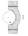
- Figure 20 shows three hydrostatically supported, spherically backed pivoted pads mounted in the main bearing caps for an internal combustion engine. This is an application where squeeze film effects are important. Such a main bearing cap package should eliminate the film breakdown which now occurs under heavy load/low rpm conditions. Because squeeze film effects set up during each full engine cycle load reversal will eliminate the possibility of yaw instability, spherical hydrostatic surfaces of the pivoted pads of the main bearing cap are permissible and desirable to produce essentially perfect wedge film geometry for minimum main bearing friction.
- the outside part of the roller bearing assembly has its corresponding component in outer support ring 94.
- the inside curvature of ring 94 is machined with six cylindrical hydrostatic pad receiving surfaces which mount corresponding hydrostatically supported pivoting pads 92.
- Such pivoted pad sliders have load bearing capacity and friction values near those of optimally pivoted pads, as is illustrated with Figure 30 of "Analysis and Design of Sliding Bearings" in the Standard Handbook of Lubrication Engineering, op cit.
- Figure 21b shows a sectional view on G-G of Figure 21a with a view of three pivoting pads 92 and also shows the grease seals and grease flow control geometry of end rings 100.
- a cross section along dashed line C is shown in exploded Figure 21c to show a grease distribution groove.
- Pressure distribution holes analogous to those of the pad of Figure 5 are shown in the view of 21b.
- the greased packed bearing will have the advantage of no external lubrication requirement.
- a grease lubricated pivoted pad arrangement such as that shown in Figures 21a - 21c should be characterized by an infinite fatigue life and essentially zero wear so long as the grease does not deteriorate.
- the design is potentially superior to that of roller bearings in many practical applications.
- the load bearing capacity of the hydrostatically supported pivoted pad arrangement of the present invention is limited by pad deformations and precision of manufacture. With careful design and very smooth surfaces, extremely heavy loads can be borne. Since these heavy loads involve quite thin oil films, problems of oil-borne particles must be considered. In many applications, for example the main bearing cap application illustrated in Figure 20, it is believed that the best solution to the particle problem is to build the pivoted pads and the corresponding surfaces in the hydrostatically pivoted support structure surfaces of very hard, very smooth material, so that the hardened surfaces act to crush and clear particles. The stresses involved in this crushing are less than the contact stresses involving the same materials in cams and tappets in the same engines with the same oils.
- the present invention produces a very stiff and very strong pivot structure which permits the pivoted plane slider bearing to be used at extremely high bearing loads.
- the support structure and pad arrangement is geometrically compact and should be inexpensive to mass produce. It is expected that the pivot structure disclosed here will permit Kingsbury-type bearings to be practically applied to the very highly loaded bearings of internal combustion engines, and also to a large number of highly loaded mechanical assemblies utilizing oil or grease bearings.
Landscapes
- Engineering & Computer Science (AREA)
- General Engineering & Computer Science (AREA)
- Mechanical Engineering (AREA)
- Physics & Mathematics (AREA)
- Fluid Mechanics (AREA)
- Sliding-Contact Bearings (AREA)
- Magnetic Bearings And Hydrostatic Bearings (AREA)
Applications Claiming Priority (2)
| Application Number | Priority Date | Filing Date | Title |
|---|---|---|---|
| US50246883A | 1983-06-09 | 1983-06-09 | |
| US502468 | 1983-06-09 |
Publications (2)
| Publication Number | Publication Date |
|---|---|
| EP0128746A2 true EP0128746A2 (de) | 1984-12-19 |
| EP0128746A3 EP0128746A3 (de) | 1985-10-09 |
Family
ID=23997962
Family Applications (1)
| Application Number | Title | Priority Date | Filing Date |
|---|---|---|---|
| EP84303854A Withdrawn EP0128746A3 (de) | 1983-06-09 | 1984-06-07 | Hochbelastbares Gleitlager mit einem hydrostatisch abgestützten Kippsegment |
Country Status (3)
| Country | Link |
|---|---|
| EP (1) | EP0128746A3 (de) |
| JP (1) | JPS6040813A (de) |
| BR (1) | BR8402796A (de) |
Cited By (6)
| Publication number | Priority date | Publication date | Assignee | Title |
|---|---|---|---|---|
| EP0236831A3 (en) * | 1986-03-05 | 1988-01-13 | Bayerische Motoren Werke Aktiengesellschaft | Divided radial plain bearing for engines and machines, especially bearing for a connecting rod and/or a crank shaft in combustion engines |
| EP0307028A3 (en) * | 1987-09-05 | 1989-12-06 | Societe Industrielle Des Coussinets Sa | Bearings |
| RU2318142C1 (ru) * | 2006-06-29 | 2008-02-27 | Марк Ионович Розно | Способ сборки двигателя внутреннего сгорания |
| DE10307945B4 (de) * | 2002-02-25 | 2021-04-29 | Caterpillar Inc. | Verbindungsanordnung einer Raupenkette zur Vermeidung von Verschleiß |
| CN113027921A (zh) * | 2021-02-09 | 2021-06-25 | 太原重工股份有限公司 | 获取静动压轴承油膜压力分布的方法和装置 |
| CN115789078A (zh) * | 2022-11-14 | 2023-03-14 | 郑州机械研究所有限公司 | 一种变曲率自适应工况的滑动轴承 |
Family Cites Families (3)
| Publication number | Priority date | Publication date | Assignee | Title |
|---|---|---|---|---|
| FR999317A (de) * | 1952-01-29 | |||
| US3549215A (en) * | 1968-10-21 | 1970-12-22 | Pioneer Motor Bearing Co | Hydrostatically supported tilting pad journal bearing |
| US4059318A (en) * | 1976-09-02 | 1977-11-22 | Pioneer Motor Bearing Co. | Hydrostatically supported tilting pad journal bearing improvements |
-
1984
- 1984-06-07 EP EP84303854A patent/EP0128746A3/de not_active Withdrawn
- 1984-06-08 BR BR8402796A patent/BR8402796A/pt unknown
- 1984-06-09 JP JP11897784A patent/JPS6040813A/ja active Pending
Cited By (6)
| Publication number | Priority date | Publication date | Assignee | Title |
|---|---|---|---|---|
| EP0236831A3 (en) * | 1986-03-05 | 1988-01-13 | Bayerische Motoren Werke Aktiengesellschaft | Divided radial plain bearing for engines and machines, especially bearing for a connecting rod and/or a crank shaft in combustion engines |
| EP0307028A3 (en) * | 1987-09-05 | 1989-12-06 | Societe Industrielle Des Coussinets Sa | Bearings |
| DE10307945B4 (de) * | 2002-02-25 | 2021-04-29 | Caterpillar Inc. | Verbindungsanordnung einer Raupenkette zur Vermeidung von Verschleiß |
| RU2318142C1 (ru) * | 2006-06-29 | 2008-02-27 | Марк Ионович Розно | Способ сборки двигателя внутреннего сгорания |
| CN113027921A (zh) * | 2021-02-09 | 2021-06-25 | 太原重工股份有限公司 | 获取静动压轴承油膜压力分布的方法和装置 |
| CN115789078A (zh) * | 2022-11-14 | 2023-03-14 | 郑州机械研究所有限公司 | 一种变曲率自适应工况的滑动轴承 |
Also Published As
| Publication number | Publication date |
|---|---|
| EP0128746A3 (de) | 1985-10-09 |
| BR8402796A (pt) | 1985-05-21 |
| JPS6040813A (ja) | 1985-03-04 |
Similar Documents
| Publication | Publication Date | Title |
|---|---|---|
| US3708215A (en) | Hybrid boost bearing assembly | |
| US7766550B2 (en) | Centering mechanisms for turbocharger bearings | |
| EP0617762B1 (de) | Verfahren zur Herstellung einer Lagerhalbschale und Lagerhalbschale nach diesem Verfahren | |
| US4777866A (en) | Variable displacement radial piston pumps or motors | |
| EP0466076A2 (de) | Spiralrillengleitringdichtung | |
| US6079102A (en) | Journal bearing method employing self-stabilizing, true-tilting pad with abruptly-stepped pocket | |
| CN107795577B (zh) | 一种径向滑动轴承 | |
| US4551082A (en) | Bearing device of sealed type scroll compressor | |
| US5360273A (en) | Hydrostatic rotor bearing having a pivoted pad | |
| CN108317172B (zh) | 一种基于柔性支承的轴承系统及控制方法 | |
| JPS5936081B2 (ja) | 容積式流体装置 | |
| US5704272A (en) | Axial piston energy converting device | |
| US3827337A (en) | Hydrostatic bearings for the swash plate of a barrel-cylinder hydraulic pump or motor | |
| EP0128746A2 (de) | Hochbelastbares Gleitlager mit einem hydrostatisch abgestützten Kippsegment | |
| US4222718A (en) | Linear motion thrust block for hydraulic pumps and motors | |
| US4508011A (en) | Hydraulic axial piston machine | |
| CN109899380A (zh) | 由单可倾瓦块与静压油腔协同工作的动静压轴承 | |
| US3211105A (en) | Hydraulic pump or motor | |
| JPH07305721A (ja) | 自動調心スラストすべり軸受 | |
| US5447376A (en) | Package bearing system | |
| Salamone | Journal Bearing Design Types And Their Applications To Turbomachinery. | |
| WO1994001690A1 (en) | Improved bearing assembly | |
| GB1593731A (en) | Axial piston hydraulic machines | |
| JPH06330849A (ja) | 可変容量型斜板式液圧機械 | |
| US5127660A (en) | Support mechanism for fluid film seals |
Legal Events
| Date | Code | Title | Description |
|---|---|---|---|
| PUAI | Public reference made under article 153(3) epc to a published international application that has entered the european phase |
Free format text: ORIGINAL CODE: 0009012 |
|
| AK | Designated contracting states |
Designated state(s): DE FR GB IT SE |
|
| PUAL | Search report despatched |
Free format text: ORIGINAL CODE: 0009013 |
|
| AK | Designated contracting states |
Designated state(s): DE FR GB IT SE |
|
| STAA | Information on the status of an ep patent application or granted ep patent |
Free format text: STATUS: THE APPLICATION IS DEEMED TO BE WITHDRAWN |
|
| 18D | Application deemed to be withdrawn |
Effective date: 19860610 |
|
| RIN1 | Information on inventor provided before grant (corrected) |
Inventor name: SHOWALTER, MERLE ROBERT |