EP0128807A1 - Dispositif pour le soulèvement et le remorquage d'un véhicule - Google Patents
Dispositif pour le soulèvement et le remorquage d'un véhicule Download PDFInfo
- Publication number
- EP0128807A1 EP0128807A1 EP84401096A EP84401096A EP0128807A1 EP 0128807 A1 EP0128807 A1 EP 0128807A1 EP 84401096 A EP84401096 A EP 84401096A EP 84401096 A EP84401096 A EP 84401096A EP 0128807 A1 EP0128807 A1 EP 0128807A1
- Authority
- EP
- European Patent Office
- Prior art keywords
- frame
- vehicle
- sub
- lifting frame
- lifting
- Prior art date
- Legal status (The legal status is an assumption and is not a legal conclusion. Google has not performed a legal analysis and makes no representation as to the accuracy of the status listed.)
- Ceased
Links
- 230000033001 locomotion Effects 0.000 claims abstract description 36
- 238000011068 loading method Methods 0.000 claims description 25
- 230000000694 effects Effects 0.000 claims description 12
- 239000000725 suspension Substances 0.000 claims description 10
- 210000003127 knee Anatomy 0.000 claims description 9
- 230000005540 biological transmission Effects 0.000 claims description 2
- 238000010276 construction Methods 0.000 description 3
- 239000000463 material Substances 0.000 description 2
- 241000212384 Bifora Species 0.000 description 1
- 229910000831 Steel Inorganic materials 0.000 description 1
- NUFNQYOELLVIPL-UHFFFAOYSA-N acifluorfen Chemical compound C1=C([N+]([O-])=O)C(C(=O)O)=CC(OC=2C(=CC(=CC=2)C(F)(F)F)Cl)=C1 NUFNQYOELLVIPL-UHFFFAOYSA-N 0.000 description 1
- 238000005452 bending Methods 0.000 description 1
- 230000009977 dual effect Effects 0.000 description 1
- 239000000446 fuel Substances 0.000 description 1
- 238000007689 inspection Methods 0.000 description 1
- 238000000034 method Methods 0.000 description 1
- 238000005192 partition Methods 0.000 description 1
- 230000000284 resting effect Effects 0.000 description 1
- 239000010959 steel Substances 0.000 description 1
Images


Classifications
-
- B—PERFORMING OPERATIONS; TRANSPORTING
- B60—VEHICLES IN GENERAL
- B60P—VEHICLES ADAPTED FOR LOAD TRANSPORTATION OR TO TRANSPORT, TO CARRY, OR TO COMPRISE SPECIAL LOADS OR OBJECTS
- B60P3/00—Vehicles adapted to transport, to carry or to comprise special loads or objects
- B60P3/12—Vehicles adapted to transport, to carry or to comprise special loads or objects for salvaging damaged vehicles
- B60P3/125—Vehicles adapted to transport, to carry or to comprise special loads or objects for salvaging damaged vehicles by supporting only part of the vehicle, e.g. front- or rear-axle
Definitions
- This invention relates to improved lifting and towing apparatus for vehicles and in particular relates to lifting and towing apparatus adapted to be mounted beneath the floor at the rear portion of a vehicle.
- the invention is particularly suited to, although not limited to, light vehicles such as pick-up trucks and various types of recreational and utility vehicles.
- a hydraulic ram is provided for pivoting the arm and the linkage operatively connects the ram to the arm.
- the linkage is arranged such that it converts horizontal movements of the ram to vertical movement lifting the arm so that the arm may be elevated to provide better ground clearance for the lift, an effort also being made in the design to provide a somewhat more uniform power ratio for the ram.
- the known prior art devices suffer from a number of disadvantages.
- One serious disadvantage is that they apply, when in use, a very substantial amount of additional strain to the main frame of the vehicle and, if the loadings are high, substantial damage can occur.
- the extra loadings on the vehicle incurred as a result of the weight of the vehicle being towed must be taken up by the main springs of the vehicle with the result being that the vehicle tends to "squat down" or sway under the influence of these loadings. This is most undesireable since it reduces the available ground clearance and may make the tow vehicle unstable.
- the prior art devices generally tend to reduce the available ground clearance to an unacceptable degree, especially when loaded, and, moreover, such devices do not allow for the use of the normal rear vehicle bumper when in the inactive or retracted mode.
- Certain of the prior art arrangements are also difficult to attach or remove from the vehicle with the result being that the lift-tow arrangement tends to be left on the vehicle at all times thus in some cases reducing its usefulness for other types of work or, at the least, creating additional weight which must be carried around at all times with a resulting reduction in fuel economy.
- lifting and towing apparatus which is of simple and relatively sturdy construction, which may be manufactured and sold at a reasonable cost, which unit is compact and, as noted above, is arranged such that the original styling of the towing vehicle is substantially maintained.
- a lifting and towing apparatus in accordance with one aspect of the invention is adapted to be mounted below the body of a vehicle having a main frame and an axle assembly with suspension springs located between the axle assembly and main frame.
- the lifting and towing apparatus typically includes bracket means and means defining a main pivot axis which is connectable to rearwardly disposed portions of the main frame of the vehicle.
- a lifting frame is pivotally secured to these bracket means for pivotal movement between raised and lowered positions to effect the raising and lowering of another vehicle when secured to the lifting frame.
- Actuator means are operatively connected to the lifting frame. for effecting the pivoting movement of same.
- One feature of the invention provides load transmitting means operatively connected to the actuator means and moveable simultaneously with the, lifting frame to a position such that loadings apply to the lifting frame are transferred from the main frame of the vehicle to the axle assembly of same via such load transmitting means. This is done such that the suspension springs are at least partially isolated from loadings applied to the lifting frame thus effectively reducing the tendancy for the vehicle to squat down or sway under the extra loadings applied by the vehicle being lifted or towed.
- the load transmitting means comprises an elongated sub-frame which is adapted to be mounted to the main frame of the vehicle for movement longitudinally of same.
- This sub-frame is connected to the lifting frame via a second pivot means which is spaced from the main pivot axis. Accordingly, longitudinal movement of the sub-frame causes the pivotting movement of the lifting frame.
- the actuator means are operatively connected via the sub-frame to the lifting frame.
- the sub-frame includes knee portions therein adapted to come into close proximity to the axle assembly of the vehicle when in a position corresponding to the raised position of the lifting frame to effect the transmission of forces therebetween.
- the above-noted sub-frame is preferably in the form of a pair of spaced elongated members each locatable beneath a respective one of the main frame members. Attachment means are provided for securing the sub-frame to the main frame and permitting sliding motion of the sub-frame relative thereto.
- the above-noted actuators preferably comprise hydraulic cylinders extending longitudinally of the sub-frame members and adapted to effect sliding movement thereof to effect the raising or lowering of the lifting frame.
- the use of the elongated sub-frame is of importance quite apart from its capability of transmitting loads from the main frame to the axle assembly.
- the elongated sub-frame in use, performs a dual function in that it serves to operatively connect the actuator means to the lifting frame and, in addition, serves to reinforce the vehicle main frame and reduce bending moments in same.
- This particular arrangement employing longitudinally extending actuators and longitudinally moveable sub-frame also provides for excellent ground clearance capability as compared with various prior art devices.
- the apparatus includes means for engaging the vehicle to be lifted and towed, which means are connected to the lifting frame via a telescoping assembly.
- a hydraulic actuator within the telescoping assembly moves the engaging means between a position in close proximity to the lifting frame to a position spaced therefrom.
- the above-noted means for engaging includes a vehicle bumper section with pivot means being provided to permit rotation of such vehicle bumper section about both horizontal and vertical axes when in a position which is spaced from the lifting frame. Means are also provided to secure the bumper section in a fixed position when retracted. A pair of spaced bumper sections are affixed to the bracket means and disposed in flanking relation to the intermediate bumper section when the latter is in its retracted position.
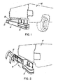
- FIG. 1 there is shown a portion of the lifting and towing apparatus in accordance with the invention including an intermediate bumper portion 12 and a pair of spaced bumper sections 14 arranged in flanking relationship to the intermediate bumper portion 12.
- Intermediate bumper portion 12 is essentially flush with the bumper portions 14 when the bumper portion 12 is in the retracted position shown in Fig. 1.
- the intermediate bumper portion 12 is secured to a lifting frame 16, a portion of which is visible in Fig. 1, such lifting frame 16 being disposed at and extending generally transversely on the rear portion of the vehicle.
- this lifting frame 16 is shown as having been pivotted to its raised position and it will be seen that the intermediate bumper portion 12 has been shifted outwardly and away from the lifting frame 16 and this is the position that it occupies when another vehicle (not shown) is being towed.
- the intermediate bumper portion 12 is capable of pivotal movement relative to the lifting frame 16 about both horizontal and vertical axes thereby to accommodate the usual pitching and yawing movements which take place during the course of a lifting and towing operation.
- the apparatus includes a pair of spaced main bracket plates 20 which are connectable to rewardly disposed portions of the main frame 22 (shown in phantom in Fig. 3) of the vehicle.
- a main pivot shaft 24 defining a main pivot axis extends through and is supported by the spaced bracket plates 20.
- the previously noted lifting frame 16 is mounted on this main pivot shaft 24 so that it can be rotated between the lowered position shown in Figs. 1, 3 and 4 and the raised position shown in Figs. 2, 6 and 10.
- the lifting frame 16 extends transversely of the rear portion of the vehicle and it is of a sturdy welded construction. It includes end plates 26 disposed immediately inwardly of the main bracket plates 20, a centrally located box-like housing portion 28, and an outer shroud or casing portion 30 made of relatively heavy steel plate which defines the top and rearwardly facing surfaces of the lifting frame.
- This shroud 30 is securely welded to the end-plates 26 and the centrally located housing portion 28 and this, together with the diagonally arranged braces 32 provides the lifting frame 16 with the necessary structural strength and rigidity.
- outer fixed bumper portions 14 are securely connected to the main bracket plates 20 by suitable fasteners (not shown) with brace members 34 assisting in providing the necessary rigidity.
- One of these fixed bumper portions 14 serves to mount a pair of control levers 36 for the hydraulic actuators to be hereafter described.
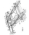
- Both the end-plates 26 and the central housing portion 28 of the lifting frame 16 have forwardly extended portions having aligned apertures therein through which extends a second pivot shaft 40.
- This pivot shaft 40 also extends through aligned apertures provided in the rear end portions of an elongated sub-frame 42 which is supported beneath the main frame 22 of the vehicle for longitudinal movement relative thereto in the manner best illustrated in Figs. 5 and 6.
- Sub-frame 42 includes a pair of spaced elongated frame members 44 each of which is locatable beneath a respective one of the members of the main frame 22. Suitable attachment means including hanger brackets 46 serve to secure the sub-frame 42 beneath the main frame and permit sliding motion of the sub-frame 42 relative to the main frame.
- sub-frame 42 Since, as noted previously, the rear end portions of sub-frame 42 are secured to lifting frame 16 via the second pivot shaft 40, and since.the second pivot shaft 40 is spaced from and positioned well below the main pivot shaft 24 as best seen in any of Figs. 5 through 10, it will readily been seen that longitudinal movement of sub-frame 42 causes pivotal movement of lifting frame 16 about the main pivot shaft 24. Hence,-as sub-frame 42 is moved rearwardly, the lifting frame 16 is rotated to its fully raised position and as sub-frame is moved forwardly relative to the vehicle, lifting frame 16 is rotated to its fully down position.
- sub-frame 42 In order to effect the above-noted longitudinal movement of sub-frame 42, there is provided a spaced apart pair of double acting hydraulic actuators 48, the rams of which are connected to sub-frame members 44 via respective brackets 50.
- the sub-frame 42 also includes diagonally arranged force transmitting members 52 which extend from brackets 50 inwardly toward the forwardly extending portions of the box-like housing portion 28 of lifting frame 16. It will be seen hereafter that it is this housing portion 28 which is required to accommodate the loadings imposed by a vehicle being lifted and towed by the apparatus.
- the opposing forwardly disposed ends of hydraulic actuators 48 are pivotally connected to respective brackets 54 by way of a third pivot shaft 56.
- These brackets 54 are rigidly connected to the main bracket plates 20 via respective elongated reaction members 58 each of which overlies a respective one of the members 44 of the sub-frame 42.
- the reaction members are provided with spaced apart pads 60 which bear against the sub-frame members to reduce friction and wear.
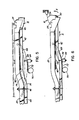
- a transversely extending bar 64 is secured by brackets 66 to the leaf-type suspension springs 68 (shown in phantom) of the vehicle just rearwardly of the rear axle housing 70 of the vehicle.
- Relatively short load transfer plates 72 each disposed directly beneath a respective one of the sub-frame members 44, have their rearward ends connected to the elongated bar 64 and their forward ends resting directly on the rear axle housing 70.
- the main members 44 of sub-frame 42 are each provided with a reversely curved section 74 defining a knee portion 76 on each frame member 44.
- the lifting frame 16 will now be further described with particular reference to Figs. 7 through 10.
- the centrally disposed box-like housing portion 28 has been briefly referred to previously.
- This housing portion 28 serves to slidably support a telescoping member 80, the latter being a tubular member of an essentially square cross-section.
- Member 80 is slidably disposed within housing portion 28 for movement in the direction of arrow C.
- the interior of housing portion 28 is provided with internal partitions 82 (shown in phantom in Fig. 9) which, together with the sidewalls of housing portion 28, serve to guide and support the telescoping member 80.
- hydraulic actuator 84 also visible in Figs. 3 and 4, is connected to the housing portion 28 of lifting frame 16 via the previously described main pivot shaft 24.
- the ram of hydraulic actuator 84 is connected to the outer end of telescoping member 80 via a shaft 86, such shaft 86 also serving to pivotally secure a load bracket 88 to the outer end of the telescoping member 80.
- Load bracket 88 includes spaced arm portions 89 which flank member 80 and through which arms shaft 86 passes. Shaft 86 permits load bracket 88 to be rotated about the end of the telescoping member in the direction of arrow D. This load bracket, in turn, serves to support the previously described intermediate bumper portion 12.
- Fig. 7 it will be seen that the lifting frame 16 is in its "down” position and that the telescoping member 80 has been fully retracted thereby to bring the intermediate bumper portion 12 into its "home” position such bumper portion 12 being seated on rest portions 92 defined by rearwardly extending portions of the main bracket plates 20.
- Fig. 8 it will be seen that the sub-frame 42 has been moved rearwardly in the direction of arrow A by virtue of the force imparted by the two hydraulic actuators 48 thus causing the lifting frame 16 to be rotated clockwise in the direction of arrow B. Then, with reference to Fig. 9, hydraulic actuator 84 is activated thereby to extend the telescoping member 80 in the direction of arrow C. In this extended condition, towing chains 100 are connected to the rear axle of the vehicle to be towed in an entirely conventional manner. In the course of this action, the load bracket and intermediate bumper section pivot about shaft 86 thereby to bring the rear face of bumper section 12 into abutting relationship with the rear bumper of the vehicle to be towed.
- the towing chains 100 may be connected to the intermediate bumper portion 12 by means of flexible elements 102 made out of wide strips of heavy duty belting material.
- the towing chains and the belting material 102 are well known, per se, in the art of lifting and towing vehicles and form no part of the present invention. Those skilled in the art will readily appreciate how the same are to be used and attached to the lifting and towing arrangement of the present invention.
- control levers 36 for the hydraulic actuators are located on one of the fixed bumper portions 14 as previously described, the operator can readily observe the operation of the lifting and towing apparatus and thus effect close control of the hydraulic actuators.
- the hydraulic actuators are operated through suitable valve systems operatively connected to the valve control levers 36 from a hydraulic pump in a conventional manner. Accordingly a description of the hydraulic control system is not required.
- the hydraulic pump may be incorporated into the lifting and towing arrangement or the system may be run off an existing hydraulic pump in the engine area of the tow vehicle.
- the lifting and towing apparatus described herein possesses numerous advantages over prior art devices. As previously noted, the apparatus does not obstruct the box or loading area of the truck in any way and moreover it is very compact and maintains the original styling of the towing vehicle. This is readily apparent from an inspection of Fig. 1 wherein it will be seen that the lifting and towing apparatus, in the retracted position, is scarcely noticable. Furthermore, the use of the unique sub-frame system coupled with the load transmitting capability substantially eliminates "squatting down" of the rear portion of the towing vehicle under the loads imposed by the vehicle being towed. Side sway or roll of the towing vehicle is also substantially eliminated and this is an important safety feature.
- the sub-frame arrangement described also substantially reduces stresses imposed on the main frame of the towing vehicle.
- the configuration described also provides for good weight distribution thus assisting in ensuring that an adequate degree of weight is applied to the front axle of the towing vehicle thereby to ensure that steering control is adequately maintained.
- the lifting and towing apparatus can also be made and sold at a relatively low cost; it is thus a relatively affordable unit applicable to a wide range of vehicles such as pick-up trucks in the one-quarter to one ton range and also recreational vehicles such as those known under the trade marks "Bronco”, “Blazer”, and “Jeep”. By virtue of the affordability of the unit, it will be particularly attractive to small service station operators and garage owners.
- the lifting and towing apparatus may also be attached or removed from the towing vehicle in the completely assembled condition. As noted previously it can be attached or detached in a relatively short period of time by unskilled personal using conventional tools and techniques.
- the apparatus according to the invention also provides for relatively high clearance ie. there is no significant loss in the original ground clearance of the vehicle and, by virtue of the load transmitting capability of the sub-frame and the associated equipment, this ground clearance is not lost to any significant degree when a vehicle is being towed.
Landscapes
- Engineering & Computer Science (AREA)
- Health & Medical Sciences (AREA)
- Public Health (AREA)
- Transportation (AREA)
- Mechanical Engineering (AREA)
- Vehicle Body Suspensions (AREA)
- Devices For Conveying Motion By Means Of Endless Flexible Members (AREA)
- Forklifts And Lifting Vehicles (AREA)
Applications Claiming Priority (2)
| Application Number | Priority Date | Filing Date | Title |
|---|---|---|---|
| CA429199 | 1982-05-30 | ||
| CA000429199A CA1199611A (fr) | 1983-05-30 | 1983-05-30 | Attelage releveur |
Publications (1)
| Publication Number | Publication Date |
|---|---|
| EP0128807A1 true EP0128807A1 (fr) | 1984-12-19 |
Family
ID=4125353
Family Applications (1)
| Application Number | Title | Priority Date | Filing Date |
|---|---|---|---|
| EP84401096A Ceased EP0128807A1 (fr) | 1983-05-30 | 1984-05-28 | Dispositif pour le soulèvement et le remorquage d'un véhicule |
Country Status (4)
| Country | Link |
|---|---|
| US (1) | US4761110A (fr) |
| EP (1) | EP0128807A1 (fr) |
| JP (1) | JPS6045441A (fr) |
| CA (1) | CA1199611A (fr) |
Families Citing this family (8)
| Publication number | Priority date | Publication date | Assignee | Title |
|---|---|---|---|---|
| US5284415A (en) * | 1992-06-03 | 1994-02-08 | Vulcan International, Inc. | Single-powered underlift towing apparatus |
| US5269553A (en) * | 1993-02-25 | 1993-12-14 | Elmy Alonso | Towing apparatus and thrust reversal mechanism therefor |
| US5672042A (en) * | 1995-10-31 | 1997-09-30 | Jerr-Dan Corporation | Underlift assembly tow trucks |
| US6315515B1 (en) | 1995-11-07 | 2001-11-13 | Jerr-Dan Corporation | Over-center towing locking mechanism for tow truck wheel lift or the like |
| US5722810A (en) * | 1995-11-07 | 1998-03-03 | Jerr-Dan Corporation | Over-center locking mechanism for tow truck wheel-lift or the like |
| US5782596A (en) * | 1995-11-08 | 1998-07-21 | Jer-Dan Corporation | Tow truck equipped with a light weight rust resistant body assembly and an underlift assembly |
| US8459625B1 (en) * | 2009-03-31 | 2013-06-11 | Honda Motor Co., Ltd. | Device for securing vehicle body to conveyor carrier |
| US10618581B2 (en) | 2017-02-17 | 2020-04-14 | Reyco Granning, Llc | Wear pads for slider suspension |
Citations (3)
| Publication number | Priority date | Publication date | Assignee | Title |
|---|---|---|---|---|
| DE375840C (de) * | 1921-12-21 | 1923-05-18 | Otto Neuhaus | Kraftwagenkupplung fuer Anhaengewagen mit schwenkbarem Kupplungszugglied |
| US3667631A (en) * | 1971-01-22 | 1972-06-06 | Jerald W Bishop | Hydraulic utility lift for trucks |
| US3674167A (en) * | 1970-09-04 | 1972-07-04 | Bissett J Roberts | Vehicle ambulance |
Family Cites Families (8)
| Publication number | Priority date | Publication date | Assignee | Title |
|---|---|---|---|---|
| US1408002A (en) * | 1920-04-19 | 1922-02-28 | Heymoss Alois | Towing device |
| US1886681A (en) * | 1930-06-28 | 1932-11-08 | Oscar S Hubbard | Wrecking-truck |
| US2255624A (en) * | 1940-09-30 | 1941-09-09 | Leo L Luse | Trailer hitch |
| US2495493A (en) * | 1946-10-03 | 1950-01-24 | Galion Iron Works & Mfg Co | Towing hitch for portable rollers |
| US2564111A (en) * | 1949-06-20 | 1951-08-14 | James F Kimball | Vehicle pickup apparatus |
| US2625279A (en) * | 1950-05-10 | 1953-01-13 | Delbert G Dalby | Vehicle lift for wrecking trucks |
| US3871535A (en) * | 1974-01-02 | 1975-03-18 | Joseph G Fenske | Vehicle hitch |
| US4274791A (en) * | 1978-12-20 | 1981-06-23 | Moon Gary D | Towing and hoisting apparatus |
-
1983
- 1983-05-30 CA CA000429199A patent/CA1199611A/fr not_active Expired
-
1984
- 1984-05-28 EP EP84401096A patent/EP0128807A1/fr not_active Ceased
- 1984-05-29 JP JP59107655A patent/JPS6045441A/ja active Pending
-
1987
- 1987-02-24 US US07/018,838 patent/US4761110A/en not_active Expired - Fee Related
Patent Citations (3)
| Publication number | Priority date | Publication date | Assignee | Title |
|---|---|---|---|---|
| DE375840C (de) * | 1921-12-21 | 1923-05-18 | Otto Neuhaus | Kraftwagenkupplung fuer Anhaengewagen mit schwenkbarem Kupplungszugglied |
| US3674167A (en) * | 1970-09-04 | 1972-07-04 | Bissett J Roberts | Vehicle ambulance |
| US3667631A (en) * | 1971-01-22 | 1972-06-06 | Jerald W Bishop | Hydraulic utility lift for trucks |
Also Published As
| Publication number | Publication date |
|---|---|
| CA1199611A (fr) | 1986-01-21 |
| JPS6045441A (ja) | 1985-03-11 |
| US4761110A (en) | 1988-08-02 |
Similar Documents
| Publication | Publication Date | Title |
|---|---|---|
| US4239275A (en) | Vehicle transporter | |
| US4702662A (en) | Trailer | |
| US4948327A (en) | Towing apparatus for coupling to towed vehicle undercarriage | |
| US4451193A (en) | Wheel lift apparatus | |
| US4861221A (en) | Vehicle lifting and towing attachment | |
| US4475761A (en) | Vehicle having pivotable wall parts | |
| US5435586A (en) | Tow-high and gooseneck attachment for hauling vehicles | |
| US4318658A (en) | Tilting deck vehicle | |
| US4264262A (en) | Tow truck | |
| US3667631A (en) | Hydraulic utility lift for trucks | |
| US4815915A (en) | Under-vehicle towing apparatus | |
| GB2458478A (en) | Agricultural tractor hitch | |
| US4258765A (en) | Log splitter for a truck having a three-point snowplow hitch and hydraulic pressure system | |
| GB2045186A (en) | Vehicle stabilizer | |
| US3908842A (en) | Tow truck | |
| US4761110A (en) | Vehicle lifting and towing apparatus | |
| US4569422A (en) | Stiff leg attachment for wrecker | |
| US4265463A (en) | Combination vehicle for towing, dumping and the like | |
| US4611968A (en) | Lifting and towing apparatus for large vehicles | |
| US5494309A (en) | Self-loading piggyback-type trailer unit | |
| US6561589B2 (en) | Dual acting truck hoist | |
| US5269553A (en) | Towing apparatus and thrust reversal mechanism therefor | |
| US5005851A (en) | Truck mounted jeep having adjustable axle and loading capacity | |
| US4487544A (en) | Towing vehicle | |
| US4613274A (en) | Self-loading dump truck |
Legal Events
| Date | Code | Title | Description |
|---|---|---|---|
| PUAI | Public reference made under article 153(3) epc to a published international application that has entered the european phase |
Free format text: ORIGINAL CODE: 0009012 |
|
| AK | Designated contracting states |
Designated state(s): AT BE CH DE FR GB IT LI NL SE |
|
| 17P | Request for examination filed |
Effective date: 19850610 |
|
| 17Q | First examination report despatched |
Effective date: 19860117 |
|
| D17Q | First examination report despatched (deleted) | ||
| STAA | Information on the status of an ep patent application or granted ep patent |
Free format text: STATUS: THE APPLICATION HAS BEEN REFUSED |
|
| 18R | Application refused |
Effective date: 19870925 |
|
| RIN1 | Information on inventor provided before grant (corrected) |
Inventor name: BOUTILIER, ROLAND A. |