EP0128855B1 - Guidage de loupe pour un laminoir oblique à trois cylindres coniques - Google Patents
Guidage de loupe pour un laminoir oblique à trois cylindres coniques Download PDFInfo
- Publication number
- EP0128855B1 EP0128855B1 EP84730039A EP84730039A EP0128855B1 EP 0128855 B1 EP0128855 B1 EP 0128855B1 EP 84730039 A EP84730039 A EP 84730039A EP 84730039 A EP84730039 A EP 84730039A EP 0128855 B1 EP0128855 B1 EP 0128855B1
- Authority
- EP
- European Patent Office
- Prior art keywords
- rollers
- outlet
- rolling mill
- hollow billet
- tilting
- Prior art date
- Legal status (The legal status is an assumption and is not a legal conclusion. Google has not performed a legal analysis and makes no representation as to the accuracy of the status listed.)
- Expired
Links
- 238000005096 rolling process Methods 0.000 title claims description 16
- 230000005855 radiation Effects 0.000 claims description 4
- 238000001816 cooling Methods 0.000 claims description 3
- 238000010438 heat treatment Methods 0.000 claims description 2
- 241000237858 Gastropoda Species 0.000 description 1
- 238000009499 grossing Methods 0.000 description 1
- 230000001105 regulatory effect Effects 0.000 description 1
- 238000003303 reheating Methods 0.000 description 1
Images

Classifications
-
- B—PERFORMING OPERATIONS; TRANSPORTING
- B21—MECHANICAL METAL-WORKING WITHOUT ESSENTIALLY REMOVING MATERIAL; PUNCHING METAL
- B21B—ROLLING OF METAL
- B21B39/00—Arrangements for moving, supporting, or positioning work, or controlling its movement, combined with or arranged in, or specially adapted for use in connection with, metal-rolling mills
- B21B39/14—Guiding, positioning or aligning work
-
- B—PERFORMING OPERATIONS; TRANSPORTING
- B21—MECHANICAL METAL-WORKING WITHOUT ESSENTIALLY REMOVING MATERIAL; PUNCHING METAL
- B21B—ROLLING OF METAL
- B21B19/00—Tube-rolling by rollers arranged outside the work and having their axes not perpendicular to the axis of the work
- B21B19/02—Tube-rolling by rollers arranged outside the work and having their axes not perpendicular to the axis of the work the axes of the rollers being arranged essentially diagonally to the axis of the work, e.g. "cross" tube-rolling ; Diescher mills, Stiefel disc piercers or Stiefel rotary piercers
-
- B—PERFORMING OPERATIONS; TRANSPORTING
- B21—MECHANICAL METAL-WORKING WITHOUT ESSENTIALLY REMOVING MATERIAL; PUNCHING METAL
- B21B—ROLLING OF METAL
- B21B19/00—Tube-rolling by rollers arranged outside the work and having their axes not perpendicular to the axis of the work
- B21B19/02—Tube-rolling by rollers arranged outside the work and having their axes not perpendicular to the axis of the work the axes of the rollers being arranged essentially diagonally to the axis of the work, e.g. "cross" tube-rolling ; Diescher mills, Stiefel disc piercers or Stiefel rotary piercers
- B21B19/06—Rolling hollow basic material, e.g. Assel mills
-
- B—PERFORMING OPERATIONS; TRANSPORTING
- B21—MECHANICAL METAL-WORKING WITHOUT ESSENTIALLY REMOVING MATERIAL; PUNCHING METAL
- B21B—ROLLING OF METAL
- B21B45/00—Devices for surface or other treatment of work, specially combined with or arranged in, or specially adapted for use in connection with, metal-rolling mills
- B21B45/008—Heat shields
-
- Y—GENERAL TAGGING OF NEW TECHNOLOGICAL DEVELOPMENTS; GENERAL TAGGING OF CROSS-SECTIONAL TECHNOLOGIES SPANNING OVER SEVERAL SECTIONS OF THE IPC; TECHNICAL SUBJECTS COVERED BY FORMER USPC CROSS-REFERENCE ART COLLECTIONS [XRACs] AND DIGESTS
- Y02—TECHNOLOGIES OR APPLICATIONS FOR MITIGATION OR ADAPTATION AGAINST CLIMATE CHANGE
- Y02P—CLIMATE CHANGE MITIGATION TECHNOLOGIES IN THE PRODUCTION OR PROCESSING OF GOODS
- Y02P70/00—Climate change mitigation technologies in the production process for final industrial or consumer products
- Y02P70/10—Greenhouse gas [GHG] capture, material saving, heat recovery or other energy efficient measures, e.g. motor control, characterised by manufacturing processes, e.g. for rolling metal or metal working
Definitions
- the invention relates to a slug outlet for a cross rolling mill according to the preamble of claim 1.
- the blanks rolled in a cross rolling mill emerge from the rolling mill at a certain speed and at the same time rotate about their own axis.
- An imaginary point on the surface of the rolling stock moves in a helix around the rolling stock axis.
- FR-A-837463 describes a slug outlet with rollers arranged along the length of the outlet and inclined with respect to the longitudinal axis of the outlet.
- the slug can reach speeds of over 1000min- 1 . If you let the bladder run free at these speeds, it would be thrown out of the pad. For this reason, either closed guide tubes or roller systems are used in cross-rolling mills, which enclose the blank, but allow the same to be moved and rotated. These systems can be opened after rolling in order to be able to eject the blanks to the side after pulling out the mandrel bar. Other known systems allow a lateral ejection of the billet and mandrel bar or also a removal of the billet in the rolling line. Such guides allow the rolling of slugs, for. B. in a smoothing mill, up to. a length of about 16-18m.
- the object of the invention is to provide a device in which a large-length slab is securely guided and is supported by driven elements in both the rotation and the longitudinal movement.
- inclined rollers with a hyperbolic profile are arranged over the entire outlet length of the rolling mill, the profiles of which are adapted to the diameter range of the blanks and the inclined position and speed of the helical feed movement of the blanks.
- the speed of these rollers can vary depending on the speed of the carriage, i.e. the rolling speed, regulated and adjusted in the inclined position to the pitch angle of the helix of the blank.
- covers preventing heat radiation from the blank can be provided between the rollers arranged at a distance. These covers allow the heat radiation of the blow, i.e. delay their cooling, so that u. U. an additional reheating furnace can be dispensed with before subsequent processing.
- a precondition for the use of these covers was the safe guiding of the blanks through the hyperbolic rollers, because in this way the blanks can be arranged close to the blanks - without causing any damage.
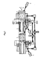
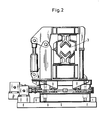
- rollers 1 In the plan view of FIG. 1, two pairs of rollers arranged one behind the other, based on the longitudinal direction of the outlet, are shown. These consist of rollers 1, of which one roller, as shown in FIG. 3, is arranged below, and the other roller is arranged opposite to it above the longitudinal axis 2 of the outlet.
- the rollers have a hyperbolic profile and can be rotated individually by drive 4.
- the drives make it possible to control as a function of the speed, and moreover the angular position of the upper or lower roller can be changed within certain limits, which is not shown in detail in the figures.
- Covers 3 can be provided between the pairs of rollers, as shown in FIG. 1, the individual design of which results from FIG. These covers ensure that the heat radiation loss of the billet between the pairs of rollers is kept as low as possible.
- heating elements such as gas burners can also exist between the pairs of rollers be those who can prevent the slug from cooling down or increase the temperature of the slug.
Landscapes
- Engineering & Computer Science (AREA)
- Mechanical Engineering (AREA)
- Metal Rolling (AREA)
- Rollers For Roller Conveyors For Transfer (AREA)
Claims (2)
Applications Claiming Priority (2)
| Application Number | Priority Date | Filing Date | Title |
|---|---|---|---|
| DE19833319771 DE3319771A1 (de) | 1983-05-27 | 1983-05-27 | Luppenfuehrung fuer ein dreiwalzen-kegelschraegwalzwerk |
| DE3319771 | 1983-05-27 |
Publications (3)
| Publication Number | Publication Date |
|---|---|
| EP0128855A2 EP0128855A2 (fr) | 1984-12-19 |
| EP0128855A3 EP0128855A3 (en) | 1985-05-02 |
| EP0128855B1 true EP0128855B1 (fr) | 1987-04-01 |
Family
ID=6200353
Family Applications (1)
| Application Number | Title | Priority Date | Filing Date |
|---|---|---|---|
| EP84730039A Expired EP0128855B1 (fr) | 1983-05-27 | 1984-04-16 | Guidage de loupe pour un laminoir oblique à trois cylindres coniques |
Country Status (3)
| Country | Link |
|---|---|
| EP (1) | EP0128855B1 (fr) |
| JP (1) | JPS59223110A (fr) |
| DE (1) | DE3319771A1 (fr) |
Families Citing this family (3)
| Publication number | Priority date | Publication date | Assignee | Title |
|---|---|---|---|---|
| DE3533119A1 (de) * | 1985-09-17 | 1987-03-26 | Kocks Technik | Schraegwalzgeruest zum walzen von hohlbloecken |
| DE4243688C1 (de) * | 1992-12-18 | 1994-03-31 | Mannesmann Ag | Verfahren und Vorrichtung zum Ausrichten einer Luppe vor dem Streckreduzierwalzwerk |
| DE102011112077B4 (de) * | 2011-09-01 | 2013-04-11 | ThyssenKrupp Federn und Stabilisatoren GmbH | Fertigungsanlage zur Herstellung von Produkten aus zylindrischen Metallstäben |
Family Cites Families (3)
| Publication number | Priority date | Publication date | Assignee | Title |
|---|---|---|---|---|
| FR837463A (fr) * | 1937-05-03 | 1939-02-10 | Mannesmann Roehren Werke Ag | Lit de refroidissement pour tubes |
| DE1271065B (de) * | 1964-03-14 | 1968-06-27 | Suedwestfalen Ag Stahlwerke | Rollgang mit in V-Profil angeordneten Rollen zum Verschwenken und Abwerfen von Stahlknueppeln od. dgl. |
| DE3001684C2 (de) * | 1980-01-18 | 1985-10-31 | Hoesch Ag, 4600 Dortmund | Vorrichtung zur Einhaltung einer gleichmäßigen Temperatur über die Bandbreite eines warmen Walzbandes |
-
1983
- 1983-05-27 DE DE19833319771 patent/DE3319771A1/de not_active Withdrawn
- 1983-12-21 JP JP58241817A patent/JPS59223110A/ja active Pending
-
1984
- 1984-04-16 EP EP84730039A patent/EP0128855B1/fr not_active Expired
Also Published As
| Publication number | Publication date |
|---|---|
| EP0128855A3 (en) | 1985-05-02 |
| EP0128855A2 (fr) | 1984-12-19 |
| DE3319771A1 (de) | 1984-11-29 |
| JPS59223110A (ja) | 1984-12-14 |
Similar Documents
| Publication | Publication Date | Title |
|---|---|---|
| EP1456421B1 (fr) | Procede et dispositif pour dresser et refroidir de maniere regulee un feuillard metallique large, notamment un feuillard d'acier ou une tole, sortant d'un laminoir a chaud pour feuillards | |
| DE19514475A1 (de) | Steckel-Walzwerk | |
| DE1917219B2 (de) | Vier-Walzen-Rundbiegemaschine | |
| EP0128855B1 (fr) | Guidage de loupe pour un laminoir oblique à trois cylindres coniques | |
| DE69108373T2 (de) | Führungsvorrichtung für das Walzen von Profilen. | |
| DE2613625B2 (de) | Maschine zum Runden oder Biegen von Stäben aus Metall | |
| DE3331339A1 (de) | Walzgeruest mit arbeits- und stuetzwalzen sowie zwischen diesen vorgesehenen zwischenwalzen | |
| DE69109945T2 (de) | Umkehrbares Walzverfahren. | |
| EP0592957B1 (fr) | Procédé et dispositif pour dresser des lamelles de bois | |
| DE3121851C2 (de) | Walzanlage mit mehreren, hintereinander angeordneten Gerüsten zum kontinuierlichen Walzen von Knüppeln | |
| DE918022C (de) | Drahtwalzstrasse | |
| EP0383786B1 (fr) | Procede de production d'un rideau d'eau | |
| DE2528850C3 (de) | Pilgerschrittwalzwerk zum Rohrkaltwalzen | |
| EP0011193B1 (fr) | Dispositif pour transférer au choix des fers moyens et marchands des trains de laminoirs continus vers des lits de refroidissement | |
| DE2123896C3 (de) | Vorrichtung zum Richten von Blechstreifen | |
| EP0849010B1 (fr) | Procédé et dispositif pour laminer à froid des tubes et des barres | |
| EP0868947B1 (fr) | Dispositif de guidage d'une loupe | |
| DE3521949C2 (de) | Universalwalzgerüst | |
| EP0062795B1 (fr) | Installation pour le transport de feuilles de verre à l'état chaud et/ou de feuilles de verre à chauffer | |
| DE2723506A1 (de) | Schraegwalzwerk zum reduzieren von langgestrecktem gut | |
| EP0129497B1 (fr) | Laminoir à cylindres obliques coniques | |
| EP0476793B1 (fr) | Laminoir pour étendre des corps creux sur un mandrin | |
| CH670239A5 (fr) | ||
| EP0788846A2 (fr) | Dispositif de guidage d'une loupe | |
| EP0703014A1 (fr) | Procédé pour laminer des blocs creux dans un laminoir de type Assel |
Legal Events
| Date | Code | Title | Description |
|---|---|---|---|
| PUAI | Public reference made under article 153(3) epc to a published international application that has entered the european phase |
Free format text: ORIGINAL CODE: 0009012 |
|
| AK | Designated contracting states |
Designated state(s): FR GB IT SE |
|
| 17P | Request for examination filed |
Effective date: 19841113 |
|
| PUAL | Search report despatched |
Free format text: ORIGINAL CODE: 0009013 |
|
| AK | Designated contracting states |
Designated state(s): FR GB IT SE |
|
| 17Q | First examination report despatched |
Effective date: 19860429 |
|
| ITF | It: translation for a ep patent filed | ||
| GRAA | (expected) grant |
Free format text: ORIGINAL CODE: 0009210 |
|
| AK | Designated contracting states |
Kind code of ref document: B1 Designated state(s): FR GB IT SE |
|
| ET | Fr: translation filed | ||
| PLBE | No opposition filed within time limit |
Free format text: ORIGINAL CODE: 0009261 |
|
| STAA | Information on the status of an ep patent application or granted ep patent |
Free format text: STATUS: NO OPPOSITION FILED WITHIN TIME LIMIT |
|
| 26N | No opposition filed | ||
| PG25 | Lapsed in a contracting state [announced via postgrant information from national office to epo] |
Ref country code: GB Effective date: 19880416 |
|
| PG25 | Lapsed in a contracting state [announced via postgrant information from national office to epo] |
Ref country code: SE Effective date: 19880417 |
|
| GBPC | Gb: european patent ceased through non-payment of renewal fee | ||
| PG25 | Lapsed in a contracting state [announced via postgrant information from national office to epo] |
Ref country code: FR Free format text: LAPSE BECAUSE OF NON-PAYMENT OF DUE FEES Effective date: 19881229 |
|
| REG | Reference to a national code |
Ref country code: FR Ref legal event code: ST |
|
| EUG | Se: european patent has lapsed |
Ref document number: 84730039.9 Effective date: 19890726 |