EP0128864B1 - Dispositif pour ramasser des végétaux se trouvant sur le sol - Google Patents
Dispositif pour ramasser des végétaux se trouvant sur le sol Download PDFInfo
- Publication number
- EP0128864B1 EP0128864B1 EP84810251A EP84810251A EP0128864B1 EP 0128864 B1 EP0128864 B1 EP 0128864B1 EP 84810251 A EP84810251 A EP 84810251A EP 84810251 A EP84810251 A EP 84810251A EP 0128864 B1 EP0128864 B1 EP 0128864B1
- Authority
- EP
- European Patent Office
- Prior art keywords
- crop
- collar
- soil
- interchangeable
- feeling
- Prior art date
- Legal status (The legal status is an assumption and is not a legal conclusion. Google has not performed a legal analysis and makes no representation as to the accuracy of the status listed.)
- Expired
Links
Images



Classifications
-
- A—HUMAN NECESSITIES
- A01—AGRICULTURE; FORESTRY; ANIMAL HUSBANDRY; HUNTING; TRAPPING; FISHING
- A01D—HARVESTING; MOWING
- A01D84/00—Haymakers not provided for in a single one of groups A01D76/00 - A01D82/00
- A01D84/02—Haymakers not provided for in a single one of groups A01D76/00 - A01D82/00 with flexible tools
-
- A—HUMAN NECESSITIES
- A01—AGRICULTURE; FORESTRY; ANIMAL HUSBANDRY; HUNTING; TRAPPING; FISHING
- A01D—HARVESTING; MOWING
- A01D84/00—Haymakers not provided for in a single one of groups A01D76/00 - A01D82/00
Definitions
- the present invention relates to a device for collecting plant material lying on the ground, with at least one drum-shaped rotor rotating about a vertical axis, which is provided at its lower end with a conical collar which carries a plurality of soil sensing and plant material receiving elements.
- the plant material lying on the ground was harvested or put into windrows by various types of haymaking machines.
- the swaths were picked up by recording devices, for example a pickup, and compressed into bales in presses, or conveyed into a loading wagon or further processed in a chopper.
- All of these devices whether via a PTO shaft or ground-driven, have one thing in common: They are equipped with steel spring tines that scan the soil and work on the crop.
- These devices have one major disadvantage: the spring tines, which process and convey the crop, have only a finite lifespan. This can be explained by the stresses to which the tines are exposed due to the unevenness of the soil and the plant material to be conveyed.
- DE-A-2 843 782 shows a haymaking machine without metal tines.
- the machine has a rotatable drum on which a large number of plate-shaped floor sensing and receiving elements made of rubber are attached.
- these simple elements made of rubber lack any plant material conveying means required to improve their effectiveness.
- US-A-4 309 863 shows a similar machine, only here a single receiving element is provided which is guided around the drum.
- DE-A-2 843 775 shows a forkless haymaking machine in many variants. Variants are also shown, which are provided on the top of the conical collar with plant material conveying elements. From this patent, however, no soil scanning and plant material receiving elements are known which are provided with plant material conveying members and are designed as individually replaceable wearing parts.
- FIG. 1 Such a device, which forms the prior art, is shown in FIG. 1, the accompanying drawing.
- the device which is articulated on a three-point suspension of a tractor, essentially consists of a crossbeam into which a divided drive shaft, driven by a PTO shaft, runs, which sets three drum-shaped rotors in rotation.
- Collars made of elastic material are arranged on the underside of the rotors, which feel the ground, pick up the plant matter and, in cooperation with conveying elements, move it sideways backwards so that a swath is formed.
- This device which is designed as a haymaking machine, has the major disadvantage that the conical, flat collar is expensive and wears out quickly when in constant contact with the soil and the crop. The wear, which is particularly severe on the circumference of the flexible collar, also severely affects the quality of the device, particularly its ability to take up and convey the plant material. The user cannot be expected to have to replace this costly part as a whole again and again.
- the object of the present invention to provide such a device in which the soil sensing and planting material elements subject to wear are not only interchangeable, but have a better efficiency than previously known elements of this type.
- the soil sensing and plant material receiving elements comprise an inclined plant material conveying surface which rises against the direction of rotation, are connected to the conical collar in an angle-adjustable manner or have angle-adjustable parts and as a whole are interchangeable or are provided with interchangeable wearing parts.
- the device belonging to the prior art, in the present example a haymaking machine is shown in the figures.
- the divided drive shaft 1 drives the rotors 3 via a transmission 2.
- the entire device is connected via a three-point suspension 4 to a tractor (not shown).
- This also drives the divided drive shaft 1 via a PTO shaft 5.
- the device can also be driven by a floor drive or via V-belts.
- Collars 6 are arranged at the bottom of the rotors 3, near the ground, which assume the multiple functions of scanning the ground, taking up the plant material from the ground and conveying the plant material. The crop is conveyed both in the direction of pull and laterally in the drawing to the left.
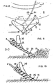
- a single rotor 3 according to the invention is shown in Figure 2. As already described with reference to FIG. 1, this is driven by the drive shaft 1 via the transmission 2.
- the flexible, outwardly directed collar 6 is held interchangeably on the rotor 3 on a frustoconical projection 7.
- the rough scanning of the floor is carried out via a support plate 8, which is connected below the collar 6 and is connected to the central axis 9.
- a plurality of elements 10 are exchangeably attached. Its upper surface has a part which rises against the direction of rotation and is designed as a plant conveying surface and is additionally provided with ribs. Depending on their function, they are called soil sensing and planting material receiving elements in the following, or shorter scanning and receiving elements 10.
- the variant shown here is flexible elements that can easily follow the unevenness of the floor while being relatively stiff in the direction of the plane of rotation.
- the scanning and receiving elements can be fastened in a variety of ways, for example by screws or rivets 11, by gluing or by a clamping ring arranged on the collar.
- the distance between the fastening points 11 and the distance A between two adjacent scanning and recording elements 10 must be large enough so that they can follow vertical movements which the elements 10 and the collar 6 carry out without cracks occurring in the collar 6.
- a flexible connecting piece 12 made of highly tear-resistant material can be provided on the collar 6 between two adjacent fastening points 11 and can also surround the entire edge of the collar 6, which prevents damage to the collar 6 by collisions with solid objects, for example stones.
- the collar 6 does not have to be made of elastic material. If, as described above, a support plate 8 is provided which takes over the rough scanning of the floor, it is sufficient if the elements 10 are flexible enough to take over the fine scanning.
- the conical collar 6 shown in FIGS. 3 to 7 has a basic shape 13 with a corrugated edge, the fin-like projecting parts 14 of which form soil sensing and plant material receiving elements.
- the soil sensing and plant material receiving elements are here provided with interchangeable parts 20, which both form an interchangeable wear protection for the receiving elements 14 and also serve to convey plant material by having an inclined surface 18 that increases in the direction of rotation.
- the front edge 16, which is particularly exposed to wear due to friction, is well protected.
- the angle of attack of the surface 18 can be adjusted, while in the embodiment according to FIG. 7 the wear part 20 also permits an angle adjustment of the bottom scanning edge.
- Figures 8-10 is again a soil sensing and planting element 10 shown, which is replaceable as a whole: attached to the collar 6.
- the elements 10 are provided here with conveyor ribs 25.
- the conveying rib closest to the leading edge 16 must also have a minimum distance 26 from the leading edge, which enables the plant material P to be picked up on the elements 10.
- the conveyor ribs 25 can also partially align with conveyor ribs 60, which are also interchangeably held on the collar 6.
- the conveying ribs 25 are made in one piece with the elements 10 in the examples shown, they can also be designed to be exchangeable.
- the element 10 according to FIG. 8 has a special feature of an interchangeable wing-like plant conveying element 30. This, too, can in turn be designed as a unit on the plant material receiving elements 10, or can be exchangeably attached to the collar 6 if the collar has integral receiving elements 14 which are shown in FIGS. 3-7.
- the plant material conveying member 30 has a plane rising in the opposite direction of rotation and resembles a wing.
- the effect of the conveying members 30 is that the soil sensing and planting material elements, which involuntarily apply soil mixed in even with the best soil sensing, do not convey them up to the rotor together with the plant material.
- FIGS. 9 and 10 also show the conveying ribs 21 attached to the elements 10 on the underside, which prevent the elements 10 from being milled into the soil, ensure soil sampling, and cause as little admixture of soil into the plant material P as possible.
- it is also essential to provide the front edge 16 with an appropriate radius.
- This radius is preferably in a range between 1 and 10 mm.
- the device according to the invention can be adapted to the crop to be processed by attaching adjustable ribs 60 to the collar 6. This requires correspondingly flexible ribs which are arranged on the collar 6 with adjustable fastening means 61 (see FIG. 13).
- FIGS. 11-13 the device is again shown as a vertical section in the area of your rotor, as in FIG. 2.
- a relatively large support plate 8, which sits on an axis 9, is shown in FIG.
- the support plate 8 can be rigidly attached to the axis 9 and only have the function of an anti-skid device, or can be rotatably held on the axis and can be set in rotary motion solely by the friction and the unevenness of the floor. But it is also possible to drive the support plate from the transmission 2.
- the soil sensing and planting material receiving elements 10 correspond to those according to FIGS. 8-10.
- the guide ribs 60 mounted on the collar 6 of the rotor here rise from the element 10 to the rotor 3 (FIG. 11) and pass into ventilation blades 62 fastened in the rotor 3. Together with the wing-like plant material conveying members 30, the plant material has a cleaning effect, as has already been described above.
- the soil sensing and plant material receiving elements can also be designed as soil-driven, rotating bodies 10 with a conveying surface that rises against the direction of rotation (FIG. 12), which are mounted on the collar 6 such that they can be rotated and exchanged.
- Such a version is particularly suitable for a device with a collar 6 made of relatively rigid material.
- FIG. 13 shows two variants again.
- the left half of the figure shows a soil sensing and plant material receiving element 10, which can swing up and down in a plane running vertically to the collar 6.
- the element 10 is pivotally attached to the collar by means of a compression spring 40 and a bolt 41.
- This movement also allows both the collar 6 and the replaceable element 10, which is designed as a wearing part, to be made from relatively rigid material.
- the oscillation of the element 10 thus allows the fine soil to be scanned and has the additional effect of transmitting the oscillation to the plant material and thereby in turn cleaning the plant material from admixed soil.
- FIG. 13 shows a soil sensing and planting material receiving element 10, which is likewise pivotable up and down in a plane running vertically to the collar.
- the collar must be made of rigid material.
- the element 10 is connected via an angled linkage 42 to a weight 43 which is exposed to the centrifugal force and which can move within the limits formed by stops 44.
- the element 10 is articulated on the collar 6 with a rubber-elastic connecting element 45. As a result of the rotary movement of the rotor 3, the weight 43 is thrown outwards and thus presses the floor scanning element 10 towards the floor. This ensures correct ground scanning even at relatively high rotational speeds.
- the conveying ribs 25 of the receiving elements are aligned with the conveying ribs 60 of the conical collar.
- the elements 10 can also move vertically to the surface of the collar 6 if the connection of the element 10 to the collar 6 takes place via a flexible intermediate piece, for example a highly tear-resistant plastic band or plate.
- the conveyor ribs 25 can also be extended such that they extend as far as the collar 6 and thus correspond in length to the conveyor ribs 60.
- the device according to the invention primarily collects the plant material lying on the ground and secondly cleans the plant material of impurities.
- the plant material is conveyed upwards by means of the plant material conveying organs (25, 30, 60). If it is conveyed by the wing-like elements 30, the plant material is thrown up so high that it can still be grasped by a subsequent device to which the device according to the invention is attached and can be further processed immediately.
Landscapes
- Life Sciences & Earth Sciences (AREA)
- Environmental Sciences (AREA)
- Soil Working Implements (AREA)
- Transplanting Machines (AREA)
Claims (9)
Priority Applications (1)
| Application Number | Priority Date | Filing Date | Title |
|---|---|---|---|
| AT84810251T ATE41727T1 (de) | 1983-06-08 | 1984-05-24 | Vorrichtung zum aufsammeln von auf dem boden liegendem pflanzengut. |
Applications Claiming Priority (2)
| Application Number | Priority Date | Filing Date | Title |
|---|---|---|---|
| CH3131/83 | 1983-06-08 | ||
| CH3131/83A CH661636A5 (de) | 1983-06-08 | 1983-06-08 | Vorrichtung zum aufsammeln und bearbeiten von auf dem boden liegendem pflanzengut. |
Publications (2)
| Publication Number | Publication Date |
|---|---|
| EP0128864A1 EP0128864A1 (fr) | 1984-12-19 |
| EP0128864B1 true EP0128864B1 (fr) | 1989-03-29 |
Family
ID=4249285
Family Applications (1)
| Application Number | Title | Priority Date | Filing Date |
|---|---|---|---|
| EP84810251A Expired EP0128864B1 (fr) | 1983-06-08 | 1984-05-24 | Dispositif pour ramasser des végétaux se trouvant sur le sol |
Country Status (5)
| Country | Link |
|---|---|
| US (1) | US4610130A (fr) |
| EP (1) | EP0128864B1 (fr) |
| AT (1) | ATE41727T1 (fr) |
| CH (1) | CH661636A5 (fr) |
| DE (1) | DE3477459D1 (fr) |
Families Citing this family (3)
| Publication number | Priority date | Publication date | Assignee | Title |
|---|---|---|---|---|
| FR2567713B1 (fr) * | 1984-07-19 | 1986-12-26 | Kuhn Sa | Perfectionnements aux machines agricoles avec au moins un tambour a axe sensiblement vertical, pour deplacer des produits se trouvant sur le sol |
| DE3443144A1 (de) * | 1984-11-27 | 1986-05-28 | Claas Saulgau GmbH, 7968 Saulgau | Schwader fuer landwirtschaftliches erntegut |
| FR2576744B1 (fr) * | 1985-02-06 | 1988-06-17 | Kuhn Sa | Perfectionnement aux jupes flexibles pour deplacer des produits se trouvant sur le sol et machines agricoles equipees de telles jupes |
Family Cites Families (6)
| Publication number | Priority date | Publication date | Assignee | Title |
|---|---|---|---|---|
| NL176215B (nl) * | 1974-08-15 | 1984-10-16 | Expert Nv | Inrichting voor het bewerken van gemaaid op het veld liggend gewas. |
| GB2005523B (en) * | 1977-10-07 | 1982-04-15 | Samibem Sa | Haymaking machine |
| FR2405008A1 (fr) * | 1977-10-07 | 1979-05-04 | Samibem Sa | Machine de fenaison sans dents metalliques |
| FR2468293A1 (fr) * | 1979-10-26 | 1981-05-08 | Belrecolt Sa | Machine de recolte a jupes perfectionnees |
| FR2471733B1 (fr) * | 1979-12-20 | 1986-10-03 | Belrecolt Sa | Machine agricole pour le fanage ou le conditionnement de vegetaux |
| FR2471734A1 (fr) * | 1979-12-20 | 1981-06-26 | Belrecolt Sa | Machine agricole pour le fanage et l'andainage de vegetaux |
-
1983
- 1983-06-08 CH CH3131/83A patent/CH661636A5/de not_active IP Right Cessation
-
1984
- 1984-05-24 EP EP84810251A patent/EP0128864B1/fr not_active Expired
- 1984-05-24 DE DE8484810251T patent/DE3477459D1/de not_active Expired
- 1984-05-24 AT AT84810251T patent/ATE41727T1/de not_active IP Right Cessation
- 1984-05-31 US US06/615,991 patent/US4610130A/en not_active Expired - Fee Related
Also Published As
| Publication number | Publication date |
|---|---|
| ATE41727T1 (de) | 1989-04-15 |
| DE3477459D1 (en) | 1989-05-03 |
| EP0128864A1 (fr) | 1984-12-19 |
| US4610130A (en) | 1986-09-09 |
| CH661636A5 (de) | 1987-08-14 |
Similar Documents
| Publication | Publication Date | Title |
|---|---|---|
| DE3854083T2 (de) | Apparat und verfahren zum ernten von feldfrüchten. | |
| DE2843775A1 (de) | Gabellose heuerntemaschine | |
| DE3850769T2 (de) | Verfahren und vorrichtung zum ernten von feldfrüchten durch abstreifen. | |
| DE2322136A1 (de) | Zuckerrohr-erntemaschine | |
| EP0212184A1 (fr) | Machine à faucher et à conditionner le fourrage | |
| EP3028559A1 (fr) | Pick-up d'une moissonneuse | |
| DE69426151T2 (de) | Reinigungsvorrichtung | |
| DE2724384A1 (de) | Landmaschine | |
| DE2844016A1 (de) | Traubenerntemaschine | |
| DE1507384A1 (de) | Dreschmaschine | |
| DE2843782C2 (de) | Kreiselheuwerbungsmaschine zum Schwadenlegen oder Schwadenwenden oder zum Zetten/Wenden | |
| DE69014465T2 (de) | Eine Hebetransportvorrichtung und ein landwirtschaftliches Trennungsgerät, das eine Hebetransportvorrichtung umfasst. | |
| EP1040746B1 (fr) | Appareil pour récolter les fruits sur pied | |
| DE102011075472B4 (de) | Erdkegelbearbeitungsvorrichtung | |
| DE2730211A1 (de) | Maehmaschine | |
| DE102010027265A1 (de) | Bodenbearbeitungsgerät | |
| DE2110622A1 (de) | Kreiselmaeher | |
| EP0176057B1 (fr) | Dispositif de hachage pour matériaux organiques | |
| DE821568C (de) | Hackfruchterntemaschine | |
| DE3039046C2 (fr) | ||
| EP0128864A1 (fr) | Dispositif pour ramasser des végétaux se trouvant sur le sol | |
| DE4215239C1 (de) | Dichtung | |
| DE3918362C2 (fr) | ||
| DE3042510A1 (de) | Zum absaugen von organischen abfaellen u.dgl. von strassenraendern, banketten, graeben und boeschungen dienendes sauggeraet | |
| DE3422426A1 (de) | Landmaschine zum verlagern von auf dem boden liegendem erntegut |
Legal Events
| Date | Code | Title | Description |
|---|---|---|---|
| PUAI | Public reference made under article 153(3) epc to a published international application that has entered the european phase |
Free format text: ORIGINAL CODE: 0009012 |
|
| AK | Designated contracting states |
Designated state(s): AT BE DE FR GB IT NL |
|
| 17P | Request for examination filed |
Effective date: 19850508 |
|
| 17Q | First examination report despatched |
Effective date: 19860321 |
|
| GRAA | (expected) grant |
Free format text: ORIGINAL CODE: 0009210 |
|
| AK | Designated contracting states |
Kind code of ref document: B1 Designated state(s): AT BE DE FR GB IT NL |
|
| REF | Corresponds to: |
Ref document number: 41727 Country of ref document: AT Date of ref document: 19890415 Kind code of ref document: T |
|
| REF | Corresponds to: |
Ref document number: 3477459 Country of ref document: DE Date of ref document: 19890503 |
|
| ITF | It: translation for a ep patent filed | ||
| ET | Fr: translation filed | ||
| GBT | Gb: translation of ep patent filed (gb section 77(6)(a)/1977) | ||
| PLBE | No opposition filed within time limit |
Free format text: ORIGINAL CODE: 0009261 |
|
| STAA | Information on the status of an ep patent application or granted ep patent |
Free format text: STATUS: NO OPPOSITION FILED WITHIN TIME LIMIT |
|
| 26N | No opposition filed | ||
| PGFP | Annual fee paid to national office [announced via postgrant information from national office to epo] |
Ref country code: BE Payment date: 19900615 Year of fee payment: 7 |
|
| PGFP | Annual fee paid to national office [announced via postgrant information from national office to epo] |
Ref country code: AT Payment date: 19910529 Year of fee payment: 8 |
|
| ITTA | It: last paid annual fee | ||
| PG25 | Lapsed in a contracting state [announced via postgrant information from national office to epo] |
Ref country code: BE Effective date: 19910531 |
|
| PGFP | Annual fee paid to national office [announced via postgrant information from national office to epo] |
Ref country code: NL Payment date: 19910531 Year of fee payment: 8 |
|
| PGFP | Annual fee paid to national office [announced via postgrant information from national office to epo] |
Ref country code: GB Payment date: 19910603 Year of fee payment: 8 |
|
| PGFP | Annual fee paid to national office [announced via postgrant information from national office to epo] |
Ref country code: DE Payment date: 19910708 Year of fee payment: 8 |
|
| BERE | Be: lapsed |
Owner name: MULLER PAUL E. Effective date: 19910531 |
|
| PG25 | Lapsed in a contracting state [announced via postgrant information from national office to epo] |
Ref country code: GB Effective date: 19920524 Ref country code: AT Effective date: 19920524 |
|
| PG25 | Lapsed in a contracting state [announced via postgrant information from national office to epo] |
Ref country code: NL Effective date: 19921201 |
|
| NLV4 | Nl: lapsed or anulled due to non-payment of the annual fee | ||
| GBPC | Gb: european patent ceased through non-payment of renewal fee |
Effective date: 19920524 |
|
| PG25 | Lapsed in a contracting state [announced via postgrant information from national office to epo] |
Ref country code: DE Effective date: 19930202 |
|
| PGFP | Annual fee paid to national office [announced via postgrant information from national office to epo] |
Ref country code: FR Payment date: 19960523 Year of fee payment: 13 |
|
| PG25 | Lapsed in a contracting state [announced via postgrant information from national office to epo] |
Ref country code: FR Free format text: LAPSE BECAUSE OF NON-PAYMENT OF DUE FEES Effective date: 19980130 |
|
| REG | Reference to a national code |
Ref country code: FR Ref legal event code: ST |