EP0128882B1 - Dispositif pour des compressions isostatiques - Google Patents
Dispositif pour des compressions isostatiques Download PDFInfo
- Publication number
- EP0128882B1 EP0128882B1 EP84850090A EP84850090A EP0128882B1 EP 0128882 B1 EP0128882 B1 EP 0128882B1 EP 84850090 A EP84850090 A EP 84850090A EP 84850090 A EP84850090 A EP 84850090A EP 0128882 B1 EP0128882 B1 EP 0128882B1
- Authority
- EP
- European Patent Office
- Prior art keywords
- press
- legs
- frame
- pressure chamber
- closure
- Prior art date
- Legal status (The legal status is an assumption and is not a legal conclusion. Google has not performed a legal analysis and makes no representation as to the accuracy of the status listed.)
- Expired
Links
Images
Classifications
-
- B—PERFORMING OPERATIONS; TRANSPORTING
- B30—PRESSES
- B30B—PRESSES IN GENERAL
- B30B11/00—Presses specially adapted for forming shaped articles from material in particulate or plastic state, e.g. briquetting presses, tabletting presses
- B30B11/001—Presses specially adapted for forming shaped articles from material in particulate or plastic state, e.g. briquetting presses, tabletting presses using a flexible element, e.g. diaphragm, urged by fluid pressure; Isostatic presses
Definitions
- the invention relates to an isostatic press including a press frame, a pressure chamber arranged in the frame and bearing against a first portion thereof, a pressure chamber closure carrying a press tool part and arranged displaceable along a path through the frame between the pressure chamber and a second portion of the frame situated directly opposite the first frame portion, an apparatus for displacing the chamber closure between the portion of the path lying in the frame and the pressure chamber, and an apparatus for carrying the chamber closure in connection with the pressure chamber during pressurizing thereof.
- Isostatic presses must withstand very high pressure, and very large forces arise with increasing press tool sizes. It has been found suitable to take up the arising forces in a frame, which axially directly supports the cylindrical pressure chamber, the pressure chamber closure (arranged movable to, and away from, the pressure chamber for allowing the insertion of a press tool carried by the closure) in a closed position indirectly bearing against the portion of the frame situated opposite the pressure chamber. It is conventional to dimension a hydraulic cylinder, adapted for displacing the closure to, and from its working position, so that it withstands the axial forces occurring when the press is pressurized. With the high axial press forces which have lately become applicable, e.g. 6000 tonnes, it has however been found practically unreasonable to dimension the hydraulic cylinder for withstanding such large loads and for being able to carry out its working stroke in a time suitable for its purpose.
- One object of the invention is therefore to provide an isostatic press with the aid of which the mentioned drawbacks are circumvented or reduced in connection with retaining the closure while the press is pressurized, guidance of press tools through the press frame and the stresses on the press frame.
- the inventive isostatic press is based on a press structure including a press frame comprising two opposite yokes which are mutually connected by means of two separate frame legs, a pressure chamber arranged in the frame and bearing against a first one of the yokes, a pressure chamber closure which carries a press tool part and is displaceable along a path through the frame generally perpendicularly to the plane of the frame between the pressure chamber and the second one of the yokes, an apparatus for displacing the chamber closure between the portion of the path situated in the frame and the pressure chamber, the apparatus which supports the chamber closure for closing of the pressure chamber during pressurization of the pressure chamber.
- the inventive improvement of the press is distinguished in that the support apparatus includes two separate support legs which are arranged pivotable in the frame plane and which at one end of the legs are journaled on the second yoke on opposite sides of and at substantially equal distances from a symmetry plane of the second yoke, and in that the free end surface of each leg surface mates with correspondingly formed bearing surfaces on the under side of a part of the displacing apparatus, which carries the closure in the press.
- the support legs can, with relatively smal inertia forces and thereby rapidly, be swung to and from their two end positions under the action of small guiding forces. Furthermore, the support legs bear against the end portions of the second frame portion i.e. the lower yoke of the frame, so that deflection of the yoke is reduced, which means that the axial length alteration oftheframe underthe action of the pressure in the press is reduced.
- each leg may be arranged to deviate by a small angle from the direction of the mean line of force in the leg so that the press forces urge the legs towards each other. In this way the support leg structure will have a self-locking function.
- each leg has a circular end surface in the above-mentioned embodiment, the centre of curvature of this circular end surface will be displaced inwards towards the interior of the frame from the mean force line of the leg.
- the support legs can furthermore have mutually opposing and complementary abutments on their free ends on the mutually opposing sides thereof, the abutments being intended to come into mutual contact in the load-bearing position of the support legs.
- the abutments will then take up the forces pressing the legs towards each other.
- detection means can be carried by the legs and preferably in association with the abutments, the detection means being adapted for indicating that the free ends of the legs have assumed a correct mutual position for carrying the closure when in register with the pressure chamber, and can be adapted such as to prevent pressurizing the pressure chamber in the absence of such indication.
- Other detection means sensing the load can be mounted on the support legs. Should there be overloading the pressurization of the pressure chamber is broken off.
- Means e.g. in the form of hydraulic cylinders, can be arranged to swing the legs between one position in which the closure can pass between the legs, and a second position in which they carry the closure when in place on the pressure chamber.
- the pivoting means may consist of hydraulic cylinders pivotably connected to the respective tension bar of the press frame and to the upper portion of each support leg.
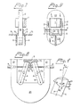
- An isostatic press is illustrated in the Figs 1. and 2 and contains a pressure chamber 1 surrounded by a press frame 2.
- the pressure chamber 1 is supported by the upper yoke 22 of the frame.
- a conveyor 71, 72, 73 for a press tool 3, 31 extends through the frame 2.
- a portion 72 of the conveyor 71-73 constitutes the lower press table and can lift the press tool 3, 31 with the aid of hydraulic cylinders 8 so that the tool is inserted into and closes off the pressure chamber 1.
- the tool 3, 31 may be regarded as comprising a magazine consisting of a die 31 and a closure 3 for the opening of the pressure chamber 1.
- two support legs 4, 5 are pivotably mounted on the lower yoke 23 of the frame 2 adjacent the frame tension bars 21 connected by the yoke 23, so that an open space can be made free for the passage of the tool 3, 31 on the conveyor 72 through the opening of the frame 2 between the support legs 4,5.
- the legs 4, 5 are retractable about their bearings on the lower yoke 23 in the plane of the frame 2 with the aid of hydraulic cylinders 6 which are pivotably mounted on the frame tension bars 21 and are connected to the support legs 4, 5.
- the free ends of the legs 4, 5 may be formed with a circular contour in the plane of the frame 2, the surface of the free ends of each leg 4, 5 mating with complementarily formed surfaces on the underside of the lower press table 72 when the legs 4, 5 are in a locked position.
- the legs 4, 5 have support abutments 41, 51 via which the legs bear against each other in the operative position of the press.
- Detectors D1 may be arranged in association with the abutments 41, 51 such that when the latter are in a mutually correct position (when the legs 4, 5 have assumed the correct position relative the press table 72) a signal departs from the detectors D allowing pressurization of the pressure chamber 1.
- Detectors D2 may be arranged at the middle of the support legs. If the support legs are overloaded a signal goes from the detectors for breaking off pressurization of the pressure chamber.
- the lower ends of the support legs 4 may have the illustrated configuration and be mounted in unillustrated spherical bearings, which are either bedded into the lower yoke 23 or mounted above it in the vicinity of the tension bars 21 at equal spacing from the plane of symmetry of the lower yoke 23.
- each leg 4 may have circular contour with a radius R, the centre of curvature C of the contour being displaced a distance a from the mean force line A of the leg.
- reaction force F of the leg towards the lower press table 72 will thus extend with an angle (a) to the mean force line A such that a locking force F, arises, which urges the legs towards each other under the action of the press force.
Landscapes
- Physics & Mathematics (AREA)
- Fluid Mechanics (AREA)
- Engineering & Computer Science (AREA)
- Mechanical Engineering (AREA)
- Press Drives And Press Lines (AREA)
- Superconductors And Manufacturing Methods Therefor (AREA)
- Glass Compositions (AREA)
- Manufacture Of Alloys Or Alloy Compounds (AREA)
- Powder Metallurgy (AREA)
Claims (9)
Priority Applications (1)
| Application Number | Priority Date | Filing Date | Title |
|---|---|---|---|
| AT84850090T ATE28056T1 (de) | 1983-04-19 | 1984-03-21 | Vorrichtung zum isostatischen pressen. |
Applications Claiming Priority (2)
| Application Number | Priority Date | Filing Date | Title |
|---|---|---|---|
| SE8302201 | 1983-04-19 | ||
| SE8302201A SE435602B (sv) | 1983-04-19 | 1983-04-19 | Isostatisk press |
Publications (2)
| Publication Number | Publication Date |
|---|---|
| EP0128882A1 EP0128882A1 (fr) | 1984-12-19 |
| EP0128882B1 true EP0128882B1 (fr) | 1987-07-01 |
Family
ID=20350882
Family Applications (1)
| Application Number | Title | Priority Date | Filing Date |
|---|---|---|---|
| EP84850090A Expired EP0128882B1 (fr) | 1983-04-19 | 1984-03-21 | Dispositif pour des compressions isostatiques |
Country Status (9)
| Country | Link |
|---|---|
| US (1) | US4563143A (fr) |
| EP (1) | EP0128882B1 (fr) |
| JP (1) | JPS59199197A (fr) |
| AT (1) | ATE28056T1 (fr) |
| AU (1) | AU580255B2 (fr) |
| BR (1) | BR8401814A (fr) |
| CA (1) | CA1224617A (fr) |
| DE (1) | DE3464470D1 (fr) |
| SE (1) | SE435602B (fr) |
Cited By (1)
| Publication number | Priority date | Publication date | Assignee | Title |
|---|---|---|---|---|
| DE10109232A1 (de) * | 2001-02-26 | 2002-09-12 | Konrad Schnupp | Riegelvorrichtung für eine Umformpresse |
Families Citing this family (9)
| Publication number | Priority date | Publication date | Assignee | Title |
|---|---|---|---|---|
| JPS6121296U (ja) * | 1984-07-13 | 1986-02-07 | 株式会社神戸製鋼所 | 高圧装置 |
| JPS6392872A (ja) * | 1986-10-03 | 1988-04-23 | Haniyuuda Tekkosho:Kk | 耐圧容器の蓋抑え装置 |
| ATE54602T1 (de) * | 1987-12-15 | 1990-08-15 | Fritsche Moellmann Gmbh Co Kg | Formwerkzeug zur herstellung eines formteiles aus mehrkomponentenkunststoff. |
| DE9007478U1 (de) * | 1989-10-31 | 1992-01-16 | Friedrich Theysohn GmbH, 4970 Bad Oeynhausen | Schwimmende Kunststoffprofilkalibriervorrichtung |
| US5057171A (en) * | 1990-04-26 | 1991-10-15 | Pacific Trinetics Corporation | Isostatic press for laminating multi-layer components and method of lamination |
| US5749331A (en) * | 1992-03-23 | 1998-05-12 | Tecsyn, Inc. | Powdered metal cylinder liners |
| US5910423A (en) * | 1995-04-28 | 1999-06-08 | Ricoh Kyosan, Inc. | Water soluble powered formulation of reagent mixture containing water-insoluble reagents, and process for their production |
| US6802195B1 (en) | 2003-04-28 | 2004-10-12 | Snap-Tite Technologies, Inc. | Isostatic press and process of using same |
| CN100496043C (zh) * | 2004-05-20 | 2009-06-03 | 华为技术有限公司 | 获取会话初始协议网络节点状态的方法及系统 |
Family Cites Families (11)
| Publication number | Priority date | Publication date | Assignee | Title |
|---|---|---|---|---|
| US2335807A (en) * | 1942-05-19 | 1943-11-30 | Aluminum Co Of America | Mold locking mechanism |
| US2395316A (en) * | 1943-12-11 | 1946-02-19 | Western Electric Co | Molding apparatus |
| US2475394A (en) * | 1946-02-13 | 1949-07-05 | Lester Engineering Co | Link mechanism for pressure casting machines |
| US2585297A (en) * | 1949-05-23 | 1952-02-12 | Rupert Diecasting Company | Aluminum die-casting machine |
| FR1322208A (fr) * | 1962-02-12 | 1963-03-29 | Système de fermeture de presse | |
| DE1255243B (de) * | 1962-07-16 | 1967-11-30 | Vinzenz Von Reimer | Spritz- oder Druckgiessmaschine |
| US3579741A (en) * | 1968-11-04 | 1971-05-25 | Lester Engineering Co | Machine and clamp force control system therefor |
| US3698843A (en) * | 1971-02-24 | 1972-10-17 | Nat Forge Co | High production isostatic molding device |
| US3867077A (en) * | 1974-05-15 | 1975-02-18 | Gleason Works | Compacting apparatus having improved rotating table means for indexing molds to and from a compacting chamber |
| US4088432A (en) * | 1977-03-01 | 1978-05-09 | Package Machinery Company | Mold lockup mechanism |
| US4243369A (en) * | 1978-12-05 | 1981-01-06 | Micro & Precision Mouldings (Cheltenham Limited) | Mould closing, clamping and opening means |
-
1983
- 1983-04-19 SE SE8302201A patent/SE435602B/sv not_active IP Right Cessation
-
1984
- 1984-03-20 US US06/591,340 patent/US4563143A/en not_active Expired - Lifetime
- 1984-03-21 EP EP84850090A patent/EP0128882B1/fr not_active Expired
- 1984-03-21 DE DE8484850090T patent/DE3464470D1/de not_active Expired
- 1984-03-21 AT AT84850090T patent/ATE28056T1/de not_active IP Right Cessation
- 1984-03-26 CA CA000450458A patent/CA1224617A/fr not_active Expired
- 1984-04-02 AU AU26324/84A patent/AU580255B2/en not_active Ceased
- 1984-04-17 BR BR8401814A patent/BR8401814A/pt unknown
- 1984-04-18 JP JP59076766A patent/JPS59199197A/ja active Granted
Cited By (2)
| Publication number | Priority date | Publication date | Assignee | Title |
|---|---|---|---|---|
| DE10109232A1 (de) * | 2001-02-26 | 2002-09-12 | Konrad Schnupp | Riegelvorrichtung für eine Umformpresse |
| DE10109232C2 (de) * | 2001-02-26 | 2003-04-03 | Konrad Schnupp | Riegelvorrichtung für eine Umformpresse |
Also Published As
| Publication number | Publication date |
|---|---|
| CA1224617A (fr) | 1987-07-28 |
| AU580255B2 (en) | 1989-01-12 |
| ATE28056T1 (de) | 1987-07-15 |
| US4563143A (en) | 1986-01-07 |
| DE3464470D1 (en) | 1987-08-06 |
| JPS59199197A (ja) | 1984-11-12 |
| AU2632484A (en) | 1984-10-25 |
| BR8401814A (pt) | 1984-11-27 |
| EP0128882A1 (fr) | 1984-12-19 |
| SE435602B (sv) | 1984-10-08 |
| JPH0411319B2 (fr) | 1992-02-28 |
| SE8302201D0 (sv) | 1983-04-19 |
Similar Documents
| Publication | Publication Date | Title |
|---|---|---|
| EP0128882B1 (fr) | Dispositif pour des compressions isostatiques | |
| US5308217A (en) | Roll chucking apparatus | |
| CN110369697A (zh) | 铸造用的自动压箱装置 | |
| US4718339A (en) | Press with chucking plates for sets of tools | |
| GB2103108A (en) | A hydraulically actuated jam release system for a jaw type rock crusher | |
| US7726961B2 (en) | Press | |
| CA1151391A (fr) | Tourelle pour poches de coulee | |
| US4850272A (en) | Articulated-lever cutting and forming press | |
| US4129173A (en) | Continuous casting plant | |
| JPS592569B2 (ja) | 平板折り曲げプレス | |
| CN111537347A (zh) | 疲劳损伤检测装置 | |
| US4573335A (en) | Hydraulic press with pressure cell | |
| KR20190088328A (ko) | 롤러형 레일 클램핑 제동장치 | |
| KR100479867B1 (ko) | 클램프 레일을 구비한 하역기의 밀림 방지장치 | |
| US3735804A (en) | Adjustable conducting roll apparatus | |
| EP0815290B1 (fr) | Presse pour restes d'anode et cosses | |
| US4836009A (en) | Upper tool support for a stamping machine or the like | |
| CA1292422C (fr) | Monture d'outil superieur pour machine de matricage ou ses analogues | |
| EP0354911B1 (fr) | Presse hydraulique avec dispositifs de serrage et d'actionnement integres colonnaires | |
| KR200243947Y1 (ko) | 카 휠 교체용 지그 | |
| CN105396934A (zh) | 一种带自动力的冲裁模具 | |
| US6802195B1 (en) | Isostatic press and process of using same | |
| US4140867A (en) | Fail-safe mechanism for electric arc furnaces | |
| JP4430920B2 (ja) | 超高圧プレス装置 | |
| CN117577472A (zh) | 一种用于矿热炉夹紧缸的微动开关及夹紧装置 |
Legal Events
| Date | Code | Title | Description |
|---|---|---|---|
| PUAI | Public reference made under article 153(3) epc to a published international application that has entered the european phase |
Free format text: ORIGINAL CODE: 0009012 |
|
| 17P | Request for examination filed |
Effective date: 19840412 |
|
| AK | Designated contracting states |
Designated state(s): AT BE CH DE FR GB IT LI LU NL SE |
|
| 17Q | First examination report despatched |
Effective date: 19860227 |
|
| ITF | It: translation for a ep patent filed | ||
| GRAA | (expected) grant |
Free format text: ORIGINAL CODE: 0009210 |
|
| AK | Designated contracting states |
Kind code of ref document: B1 Designated state(s): AT BE CH DE FR GB IT LI LU NL SE |
|
| PG25 | Lapsed in a contracting state [announced via postgrant information from national office to epo] |
Ref country code: NL Effective date: 19870701 Ref country code: LI Effective date: 19870701 Ref country code: CH Effective date: 19870701 Ref country code: BE Effective date: 19870701 Ref country code: AT Effective date: 19870701 |
|
| REF | Corresponds to: |
Ref document number: 28056 Country of ref document: AT Date of ref document: 19870715 Kind code of ref document: T |
|
| PG25 | Lapsed in a contracting state [announced via postgrant information from national office to epo] |
Ref country code: SE Effective date: 19870731 |
|
| REF | Corresponds to: |
Ref document number: 3464470 Country of ref document: DE Date of ref document: 19870806 |
|
| ET | Fr: translation filed | ||
| REG | Reference to a national code |
Ref country code: CH Ref legal event code: PL |
|
| NLV1 | Nl: lapsed or annulled due to failure to fulfill the requirements of art. 29p and 29m of the patents act | ||
| PG25 | Lapsed in a contracting state [announced via postgrant information from national office to epo] |
Ref country code: LU Free format text: LAPSE BECAUSE OF NON-PAYMENT OF DUE FEES Effective date: 19880331 |
|
| PLBE | No opposition filed within time limit |
Free format text: ORIGINAL CODE: 0009261 |
|
| STAA | Information on the status of an ep patent application or granted ep patent |
Free format text: STATUS: NO OPPOSITION FILED WITHIN TIME LIMIT |
|
| 26N | No opposition filed | ||
| ITTA | It: last paid annual fee | ||
| REG | Reference to a national code |
Ref country code: GB Ref legal event code: IF02 |
|
| PGFP | Annual fee paid to national office [announced via postgrant information from national office to epo] |
Ref country code: GB Payment date: 20030225 Year of fee payment: 20 |
|
| PGFP | Annual fee paid to national office [announced via postgrant information from national office to epo] |
Ref country code: DE Payment date: 20030305 Year of fee payment: 20 |
|
| PGFP | Annual fee paid to national office [announced via postgrant information from national office to epo] |
Ref country code: FR Payment date: 20030307 Year of fee payment: 20 |
|
| PG25 | Lapsed in a contracting state [announced via postgrant information from national office to epo] |
Ref country code: GB Free format text: LAPSE BECAUSE OF EXPIRATION OF PROTECTION Effective date: 20040320 |
|
| REG | Reference to a national code |
Ref country code: GB Ref legal event code: PE20 |