EP0128974B1 - Machine à mouler pour la production de moules ou noyaux de sable de moulage - Google Patents
Machine à mouler pour la production de moules ou noyaux de sable de moulage Download PDFInfo
- Publication number
- EP0128974B1 EP0128974B1 EP83200879A EP83200879A EP0128974B1 EP 0128974 B1 EP0128974 B1 EP 0128974B1 EP 83200879 A EP83200879 A EP 83200879A EP 83200879 A EP83200879 A EP 83200879A EP 0128974 B1 EP0128974 B1 EP 0128974B1
- Authority
- EP
- European Patent Office
- Prior art keywords
- moulding
- nozzles
- core box
- slit
- way
- Prior art date
- Legal status (The legal status is an assumption and is not a legal conclusion. Google has not performed a legal analysis and makes no representation as to the accuracy of the status listed.)
- Expired
Links
- 238000000465 moulding Methods 0.000 title claims abstract description 34
- 239000004576 sand Substances 0.000 title claims abstract description 18
- 239000012159 carrier gas Substances 0.000 claims abstract description 7
- 238000005266 casting Methods 0.000 claims abstract description 5
- 238000003825 pressing Methods 0.000 claims abstract description 4
- 239000000945 filler Substances 0.000 claims abstract 4
- 238000002347 injection Methods 0.000 claims abstract 4
- 239000007924 injection Substances 0.000 claims abstract 4
- 239000006096 absorbing agent Substances 0.000 claims abstract 2
- 230000002000 scavenging effect Effects 0.000 claims abstract 2
- 239000007789 gas Substances 0.000 description 17
- 239000003110 molding sand Substances 0.000 description 16
- 239000011230 binding agent Substances 0.000 description 7
- 239000003054 catalyst Substances 0.000 description 7
- 238000000034 method Methods 0.000 description 7
- 238000010521 absorption reaction Methods 0.000 description 4
- 238000007906 compression Methods 0.000 description 4
- 238000007789 sealing Methods 0.000 description 4
- 238000006243 chemical reaction Methods 0.000 description 3
- 230000009969 flowable effect Effects 0.000 description 3
- 238000010137 moulding (plastic) Methods 0.000 description 3
- 238000010926 purge Methods 0.000 description 3
- 239000000057 synthetic resin Substances 0.000 description 3
- 229920003002 synthetic resin Polymers 0.000 description 3
- 238000005056 compaction Methods 0.000 description 2
- 230000006835 compression Effects 0.000 description 2
- 238000013461 design Methods 0.000 description 2
- 230000000694 effects Effects 0.000 description 2
- 238000010438 heat treatment Methods 0.000 description 2
- 238000012545 processing Methods 0.000 description 2
- 239000000470 constituent Substances 0.000 description 1
- 238000007872 degassing Methods 0.000 description 1
- 230000001419 dependent effect Effects 0.000 description 1
- 238000005516 engineering process Methods 0.000 description 1
- 238000005429 filling process Methods 0.000 description 1
- 238000010304 firing Methods 0.000 description 1
- 238000011010 flushing procedure Methods 0.000 description 1
- 239000007849 furan resin Substances 0.000 description 1
- 239000012948 isocyanate Substances 0.000 description 1
- 150000002513 isocyanates Chemical class 0.000 description 1
- 238000004519 manufacturing process Methods 0.000 description 1
- 239000005011 phenolic resin Substances 0.000 description 1
- 229920001568 phenolic resin Polymers 0.000 description 1
- 239000004848 polyfunctional curative Substances 0.000 description 1
- 235000019353 potassium silicate Nutrition 0.000 description 1
- 238000002360 preparation method Methods 0.000 description 1
- 238000011084 recovery Methods 0.000 description 1
- NTHWMYGWWRZVTN-UHFFFAOYSA-N sodium silicate Chemical compound [Na+].[Na+].[O-][Si]([O-])=O NTHWMYGWWRZVTN-UHFFFAOYSA-N 0.000 description 1
- 238000003860 storage Methods 0.000 description 1
- 239000000126 substance Substances 0.000 description 1
- 238000012549 training Methods 0.000 description 1
- 238000009423 ventilation Methods 0.000 description 1
- 238000013022 venting Methods 0.000 description 1
- 238000005406 washing Methods 0.000 description 1
Images

Classifications
-
- B—PERFORMING OPERATIONS; TRANSPORTING
- B22—CASTING; POWDER METALLURGY
- B22C—FOUNDRY MOULDING
- B22C15/00—Moulding machines characterised by the compacting mechanism; Accessories therefor
- B22C15/23—Compacting by gas pressure or vacuum
-
- B—PERFORMING OPERATIONS; TRANSPORTING
- B22—CASTING; POWDER METALLURGY
- B22C—FOUNDRY MOULDING
- B22C9/00—Moulds or cores; Moulding processes
- B22C9/12—Treating moulds or cores, e.g. drying, hardening
- B22C9/123—Gas-hardening
Definitions
- the invention relates to a molding machine for producing casting molds or cores from molding sand according to the vacuum shooting principle, which consists of a mold or core box provided with a base plate and a top plate and slot nozzles, clamping jaws acting laterally on the mold or core box and a mold or core box against a lifting table pressing a sand filling device, the sand filling device being equipped with a shooting head or a fluidizing head and a gassing plate which can be pushed over the mold or core box and which can be connected via valves to a carrier source or to purging air, and wherein the slot nozzles are connected to a via a suction line Vacuum device are connected.
- the molding sand is usually introduced and compressed into the molding or core box with a very high air or gas pressure, the slot nozzles arranged in the box frame, the base plate and the top plate depending on the shape of the model Venting during the compression process and the removal of the gases formed during the hardening of the binder added to the molding sand and the purge air.
- the gases emerging from the slot nozzles are often harmful to health and must therefore be extracted and rendered harmless by means of large interception hoods covering the molding machine.
- suction devices of this type have the disadvantage that usually not all harmful gases are suctioned off and removed.
- DE-OS 30 08 235 a method is known in which two adjacent box parts are provided with air discharge openings and one vacuum chamber each, each of which is connected to a suction device via a suction line.
- the upper part of the box is connected to a sand reservoir via a shot opening and a closure device.
- the mold cavity is filled with molding or core sand according to the vacuum firing principle by means of a vacuum created suddenly in the chamber. If necessary, a subsequent compression and / or curing with a reaction or catalyst gas and a flushing with air then take place according to the air pressure pulse principle.
- This embodiment also has the disadvantage that the molded or core sands, the nature of which often changes and the flowability of which is very temperature-dependent owing to the admixed binders, are not sufficiently compacted. Curing by means of a reaction or catalyst gas blown into the compressed core is relatively slow. There is also a need to shorten the curing time for faster series production.
- the invention is therefore based on the object of designing a molding machine of the generic type in such a way that the compaction can be adapted to different and / or changing operating conditions and properties of the molding sand and the curing time is shortened.
- This training has the essential advantage that the filling and compacting of the molding sand can be adapted as best as possible to the operating conditions, in particular the type and nature of the molding sand, by filling and compacting either only by vacuum or in conjunction with the compressed gas, so that a substantial larger pressure difference is formed.
- Even poorly flowable molding sands can be injected evenly and quickly with the simultaneous use of vacuum and compressed gas.
- the effect of the vacuum has the advantage that the reaction is accelerated and less binders and catalyst substances are required. The reason for this is a more uniform gas flow through the molding or core mass.
- the vacuum device is advantageously used for degassing, so that the exhaust gases can no longer escape into the open, but are discharged in a closed system.
- the vacuum can be applied directly to the slot nozzles, whereas the gases extracted during curing are passed through an absorption device for the purpose of separating harmless components.
- a hollow slide is arranged under the base plate equipped with slot nozzles, the cavity of which is connected to the slot nozzles and the collecting tube, and the lateral clamping jaws have a cavity which corresponds to that on the relevant slot nozzles and the manifold in connection.
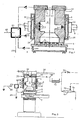
- the molding machine shown in FIGS. 1 to 3 is assigned a molding or core box 1 which is formed in two parts in the cone and whose cavity 2 corresponds to the contours of the mold or core to be manufactured. Depending on the design of the cavity 2, both halves are provided with slot nozzles 3, which are each connected to a common outlet opening via small bores.
- the molded or core box 1 rests on a base plate 4 equipped with slot nozzles 5 and is covered by a top plate 12 provided with slot nozzles 13 and a central filling opening.
- the base plate 4 rests on a hollow slide 6, the cavity of which is connected to the slot nozzles 5 of the base plate 4 via small bores.
- the hollow slide 6 is connected via a suction line to a collecting pipe 23, the meaning of which is described in more detail below.
- the hollow slide 6 is supported on a lifting table 7 which can be raised and lowered by means of a lifting cylinder.
- lateral clamping jaws 8 are provided, which can be pressed against the two halves of the mold or core box 1 by means of an adjusting cylinder 9.
- the clamping jaws 8, like the hollow slide 6, are hollow, the cavity being connected via a bore to the outlet opening assigned to the slot nozzles 3 and also connected to the collecting tube 23.
- the slot nozzles 13 of the head plate 12 are connected to the collecting pipe 23 via channels.
- FIGS. 1 to 3 The embodiment shown in FIGS. 1 to 3 is suitable for processing plastic molding sand.
- a sand filling device 10 with a shooting head 11 is arranged on an upper machine part, which has a common filling opening with the head plate 12.
- a shooting cylinder 14 Above the shooting head 11 there is a shooting cylinder 14 which is provided with slits and which is surrounded by a jacket 18 at a distance.
- a valve seat 19 is also incorporated into the jacket 18, to which a shooting valve 20 is assigned, which is acted upon by a compressed air pump 22 via a pressure line 21 becomes.
- the manifold 23 connected to the slit nozzles 3, 5 and 13 is connected via a suction line 24 provided with a valve 25 to a vacuum container 26 which is kept at a pressure of approximately 0.95 bar by a vacuum pump 27.
- a suction line 28 equipped with a check valve 29 is provided, which is connected via an absorption apparatus 30, e.g. B. a washing machine, a suction line 31 and a control valve 32 is also connected to the vacuum container 26.
- the contact surfaces of the clamping jaws 8 are provided with sealing rings 33, 34.
- the inner sealing ring 33 seals the vacuum line between the outlet bores of the slot nozzles 3 and the cavity of the clamping jaws 8.
- the above-mentioned components have the position shown in FIG. 1 for filling and compacting the plastic molding sand.
- the valve 20 controlling the compressed air and the valve 25 assigned to the vacuum device are briefly opened depending on the mold or core geometry, forming a large pressure difference.
- the valves 20, 25 are preferably linked in terms of control technology in such a way that they can be opened selectively and variably at the same time or independently of one another or overlapping in time. For example, depending on the type of molding sand, it may be useful to first generate a pre-pressure by introducing compressed air and then to connect the vacuum; With other plastic molding sands, a reverse procedure or simultaneous exposure to compressed air and vacuum can be advantageous.
- the molding machine After compaction, which takes about 0.5 to several seconds, depending on the shape or core design and the type of molding sand, the molding machine is prepared for the curing process.
- the lifting table 7 is lowered and a gassing plate 35, which is slidably mounted, for example, on guide rails 36, is pushed between the molded or core box 1 and its head plate 12; then the lifting table 7 pushed up again (see FIG. 3).
- the gassing plate 35 has a gassing channel 37 which is connected to a gassing line 38.
- the gassing line 38 is divided and connected on the one hand via a valve 40 to a carrier gas source and on the other hand via a valve 39 to a purge air line.
- a line equipped with a valve 42 for introducing catalyst gas is also provided on the branch assigned to the carrier.
- the gas passed through the gassing line 38 can be heated if necessary with a heating device 43.
- the control valve 32 assigned to the vacuum device and the valve 40 belonging to the carrier gas source are opened simultaneously.
- the binder contained in the molding sand is cured with only a small pressure difference, the vacuum on the vacuum side being able to be set by means of the control valves 32 as a function of the mold or core geometry and density.
- the choice of the carrier gas and the catalyst gas depends on the type of binder added to the molding sand. If the binder consists of water glass, for example, C0 2 is used as the carrier gas. If, on the other hand, they are polymerizable synthetic resins, N 2 can be provided as the carrier gas, to which a suitable catalyst gas is added as a hardener.
- Suitable polymerizable organic synthetic resins for molding sand are phenolic resins, isocyanates, furan resins. If thermally curable synthetic resins are to be used, the molding or core box 1 and the associated top and bottom plates 4, 12 heating devices (not shown) are provided. During the curing process and the subsequent ventilation process, in which the valve 40 is closed and the valve 39 is open, the exhaust gases are passed through the absorption apparatus 30, in which harmful constituents can be separated off.
- the molding machine is equipped with the sand filling device 44 shown in FIG. 4 instead of the sand filling device 10 shown in FIG. 1.
- a fluidizing head 46 and a sand slide 47 are arranged at the lower end of the storage container 45.
- the flowable molding sand is compressed by simultaneously opening the valve 25 associated with the vacuum device and a compressed air valve 48 assigned to the fluidizing head 46.
- a vibrator 49 mounted on the lifting table 7 can be actuated if necessary (cf. FIG. 1). ).
- the procedure for curing is the same as that explained in connection with FIGS. 1 to 3.
- the individual operations of the molding machine are controlled logically. Depending on the molding or core mass and the type of binder, a work cycle usually lasts 1 to several minutes.
Landscapes
- Engineering & Computer Science (AREA)
- Mechanical Engineering (AREA)
- Casting Devices For Molds (AREA)
- Molds, Cores, And Manufacturing Methods Thereof (AREA)
Claims (4)
Priority Applications (3)
| Application Number | Priority Date | Filing Date | Title |
|---|---|---|---|
| EP83200879A EP0128974B1 (fr) | 1983-06-16 | 1983-06-16 | Machine à mouler pour la production de moules ou noyaux de sable de moulage |
| AT83200879T ATE22825T1 (de) | 1983-06-16 | 1983-06-16 | Formmaschine zum herstellen von giessformen oder -kernen aus formsand. |
| DE8383200879T DE3366853D1 (en) | 1983-06-16 | 1983-06-16 | Moulding machine for producing moulds or cores from moulding sand |
Applications Claiming Priority (1)
| Application Number | Priority Date | Filing Date | Title |
|---|---|---|---|
| EP83200879A EP0128974B1 (fr) | 1983-06-16 | 1983-06-16 | Machine à mouler pour la production de moules ou noyaux de sable de moulage |
Publications (2)
| Publication Number | Publication Date |
|---|---|
| EP0128974A1 EP0128974A1 (fr) | 1984-12-27 |
| EP0128974B1 true EP0128974B1 (fr) | 1986-10-15 |
Family
ID=8190965
Family Applications (1)
| Application Number | Title | Priority Date | Filing Date |
|---|---|---|---|
| EP83200879A Expired EP0128974B1 (fr) | 1983-06-16 | 1983-06-16 | Machine à mouler pour la production de moules ou noyaux de sable de moulage |
Country Status (3)
| Country | Link |
|---|---|
| EP (1) | EP0128974B1 (fr) |
| AT (1) | ATE22825T1 (fr) |
| DE (1) | DE3366853D1 (fr) |
Cited By (4)
| Publication number | Priority date | Publication date | Assignee | Title |
|---|---|---|---|---|
| DE19503832A1 (de) * | 1994-02-04 | 1995-08-24 | Sommer Tech Entwicklungen Gmbh | Verfahren und Vorrichtung zur Herstellung von Sandkernen für Metallguß |
| DE19549422C2 (de) * | 1994-02-04 | 2001-05-10 | Sommer Tech Entwicklungen Gmbh | Verfahren und Vorrichtungen zur Herstellung von Sandkernen für Metallguß |
| DE102019105819B3 (de) | 2018-04-12 | 2019-10-02 | Krämer + Grebe GmbH & Co. KG Modellbau | Vorrichtung zur Herstellung von Kernen aus Formstoff |
| DE102019116531B3 (de) * | 2019-06-18 | 2020-03-26 | Krämer + Grebe GmbH & Co. KG Modellbau | Vorrichtung zur Herstellung von Kernen aus Formstoff |
Families Citing this family (9)
| Publication number | Priority date | Publication date | Assignee | Title |
|---|---|---|---|---|
| CH675552A5 (fr) * | 1988-01-08 | 1990-10-15 | Fischer Ag Georg | |
| EP0379741B1 (fr) * | 1989-01-24 | 1991-11-06 | Harald Steffens Giessereimaschinen | Procédé pour durcir des pièces façonnées, en particulier des moules et noyaux de fonderie en sable de moulage |
| DE4112701A1 (de) * | 1991-04-18 | 1992-10-22 | Dossmann Gmbh Eisengiesserei U | Verfahren und vorrichtung der herstellung von sandkernen fuer den metallguss |
| ES2053382B1 (es) * | 1992-03-16 | 1996-08-16 | Erana Agustin Arana | Mejoras en disparadoras de machos para proceso autofraguante con sistema de vacio. |
| ES2114416B1 (es) * | 1994-10-28 | 1999-01-01 | Erana Agustin Arana | Procedimiento y dispositivo de soplado de machos complejos con presion de soplado reducida. |
| DE19927107A1 (de) * | 1999-06-14 | 2000-12-21 | Fischer Georg Gmbh & Co Kg | Verfahren und Vorrichtung zur Verminderung der Geruchsemissionen von Giessereianlagen |
| CN102921902B (zh) * | 2012-11-13 | 2014-12-03 | 柳州市勤友贸易有限公司 | 铁模覆砂与铁型组芯复合造型工艺方法 |
| DE102018120993A1 (de) * | 2018-08-28 | 2020-03-05 | Fritz Winter Eisengiesserei Gmbh & Co. Kg | Verfahren zur Begasung von für die Herstellung von Gießkernen in einen Kernkasten eingeschossenem Formstoff mit einem Katalysatorgas |
| CN115533043A (zh) * | 2022-10-29 | 2022-12-30 | 衡水冀鑫智能机械科技有限公司 | 上下射砂全自动砂型造型机 |
Citations (1)
| Publication number | Priority date | Publication date | Assignee | Title |
|---|---|---|---|---|
| EP0036434A1 (fr) * | 1980-03-25 | 1981-09-30 | Eugen Dipl.-Ing. Bühler | Procédé et dispositif pour comprimer des moules en fonte |
Family Cites Families (4)
| Publication number | Priority date | Publication date | Assignee | Title |
|---|---|---|---|---|
| DE2621153A1 (de) * | 1976-05-13 | 1977-11-24 | Daimler Benz Ag | Verfahren und einrichtung zum aushaerten von sandformkoerpern |
| DE2833999C2 (de) * | 1978-08-03 | 1981-11-19 | Eugen Dipl.-Ing. 8871 Burtenbach Bühler | Verfahren und Vorrichtung zur Herstellung von Gießformen und -kernen |
| DE2923062A1 (de) * | 1979-06-07 | 1980-12-11 | Wolfgang Ing Grad Boehner | Anlegen eines vakuums an hohlraeume zwecks fuellung mit poroesen stoffen sowie an poroesen koerpern zwecks entfernen von gasen -geruch |
| DE3008235C2 (de) * | 1980-03-04 | 1983-01-27 | Eugen Dipl.-Ing. 8871 Burtenbach Bühler | Verfahren und Vorrichtung zur Herstellung von Gießformteilen und -kernen |
-
1983
- 1983-06-16 DE DE8383200879T patent/DE3366853D1/de not_active Expired
- 1983-06-16 EP EP83200879A patent/EP0128974B1/fr not_active Expired
- 1983-06-16 AT AT83200879T patent/ATE22825T1/de not_active IP Right Cessation
Patent Citations (1)
| Publication number | Priority date | Publication date | Assignee | Title |
|---|---|---|---|---|
| EP0036434A1 (fr) * | 1980-03-25 | 1981-09-30 | Eugen Dipl.-Ing. Bühler | Procédé et dispositif pour comprimer des moules en fonte |
Cited By (5)
| Publication number | Priority date | Publication date | Assignee | Title |
|---|---|---|---|---|
| DE19503832A1 (de) * | 1994-02-04 | 1995-08-24 | Sommer Tech Entwicklungen Gmbh | Verfahren und Vorrichtung zur Herstellung von Sandkernen für Metallguß |
| DE19503832C2 (de) * | 1994-02-04 | 1999-01-28 | Sommer Tech Entwicklungen Gmbh | Verfahren und Vorrichtung zur Herstellung von Sandkernen für Metallguß |
| DE19549422C2 (de) * | 1994-02-04 | 2001-05-10 | Sommer Tech Entwicklungen Gmbh | Verfahren und Vorrichtungen zur Herstellung von Sandkernen für Metallguß |
| DE102019105819B3 (de) | 2018-04-12 | 2019-10-02 | Krämer + Grebe GmbH & Co. KG Modellbau | Vorrichtung zur Herstellung von Kernen aus Formstoff |
| DE102019116531B3 (de) * | 2019-06-18 | 2020-03-26 | Krämer + Grebe GmbH & Co. KG Modellbau | Vorrichtung zur Herstellung von Kernen aus Formstoff |
Also Published As
| Publication number | Publication date |
|---|---|
| DE3366853D1 (en) | 1986-11-20 |
| EP0128974A1 (fr) | 1984-12-27 |
| ATE22825T1 (de) | 1986-11-15 |
Similar Documents
| Publication | Publication Date | Title |
|---|---|---|
| DE1921048A1 (de) | Vorrichtung und Verfahren zum Herstellen von Sandformteilen | |
| DE2833999C2 (de) | Verfahren und Vorrichtung zur Herstellung von Gießformen und -kernen | |
| EP0128974A1 (fr) | Machine à mouler pour la production de moules ou noyaux de sable de moulage | |
| DE3312539C1 (de) | Vorrichtung zum Herstellen von kastenlosen Sandgießformen | |
| DE2842912C2 (de) | Verfahren und Vorrichtung zum Herstellen von Sandgießformen o.dgl. | |
| DE3008235A1 (de) | Verfahren und vorrichtung zur herstellung von giessformteilen und -kernen | |
| DE2304564A1 (de) | Vorrichtung zur automatischen herstellung von formen und kernen fuer giessereizwecke | |
| DE1256361B (de) | Verfahren und Maschine zum Herstellen von Giessereikernen | |
| DE3249965C2 (fr) | ||
| EP0357871B1 (fr) | Machine à mouler | |
| EP1690614A1 (fr) | Machine et procédé à tirer les noyaux | |
| EP0087575B1 (fr) | Machine à mouler pour la production de moules sans châssis | |
| DE2444666A1 (de) | Hohlkern-formvorrichtung fuer das maskenformen | |
| DE1941736B1 (de) | Verfahren bei kastenlosen Formmaschinen zum Einschiessen des Formsandes und Maschine zur Durchfuehrung desselben | |
| DE2727297B2 (de) | Verfahren und Einrichtung zum Herstellen von Gießereisandformen | |
| DE2403199B2 (fr) | ||
| CH662522A5 (de) | Formmaschine zum herstellen von gasgehaerteten sandformen und verfahren zum betrieb dieser formmaschine. | |
| DE3002702A1 (de) | Vorrichtung an sandformmaschinen zum zufuehren des formsandes | |
| DE3308184C2 (fr) | ||
| DE2528646C3 (de) | Vorrichtung zur automatischen Herstellung kastenloser Gießformen | |
| DE2430403B2 (de) | Verfahren und Vorrichtung zur Gießformherstellung | |
| DE2923271A1 (de) | Giesserei-formmaschine | |
| DE2439091C2 (de) | Formvorrichtung zur Ausbildung hohler Kautschukgegenstände | |
| DE2830479A1 (de) | Verfahren und vorrichtung zum fuellen einer form zur herstellung von formlingen aus beton o.dgl. | |
| DE2607553A1 (de) | Giesserei-formmaschine fuer kastenformen |
Legal Events
| Date | Code | Title | Description |
|---|---|---|---|
| PUAI | Public reference made under article 153(3) epc to a published international application that has entered the european phase |
Free format text: ORIGINAL CODE: 0009012 |
|
| 17P | Request for examination filed |
Effective date: 19840829 |
|
| AK | Designated contracting states |
Designated state(s): AT BE CH DE FR GB IT LI LU NL SE |
|
| GRAA | (expected) grant |
Free format text: ORIGINAL CODE: 0009210 |
|
| ITF | It: translation for a ep patent filed | ||
| AK | Designated contracting states |
Kind code of ref document: B1 Designated state(s): AT BE CH DE FR GB IT LI LU NL SE |
|
| REF | Corresponds to: |
Ref document number: 22825 Country of ref document: AT Date of ref document: 19861115 Kind code of ref document: T |
|
| REF | Corresponds to: |
Ref document number: 3366853 Country of ref document: DE Date of ref document: 19861120 |
|
| ET | Fr: translation filed | ||
| PLBE | No opposition filed within time limit |
Free format text: ORIGINAL CODE: 0009261 |
|
| STAA | Information on the status of an ep patent application or granted ep patent |
Free format text: STATUS: NO OPPOSITION FILED WITHIN TIME LIMIT |
|
| 26N | No opposition filed | ||
| PGFP | Annual fee paid to national office [announced via postgrant information from national office to epo] |
Ref country code: SE Payment date: 19910612 Year of fee payment: 9 Ref country code: LU Payment date: 19910612 Year of fee payment: 9 Ref country code: BE Payment date: 19910612 Year of fee payment: 9 |
|
| PGFP | Annual fee paid to national office [announced via postgrant information from national office to epo] |
Ref country code: NL Payment date: 19910630 Year of fee payment: 9 Ref country code: AT Payment date: 19910630 Year of fee payment: 9 |
|
| EPTA | Lu: last paid annual fee | ||
| PGFP | Annual fee paid to national office [announced via postgrant information from national office to epo] |
Ref country code: FR Payment date: 19920521 Year of fee payment: 10 |
|
| PGFP | Annual fee paid to national office [announced via postgrant information from national office to epo] |
Ref country code: DE Payment date: 19920527 Year of fee payment: 10 |
|
| PGFP | Annual fee paid to national office [announced via postgrant information from national office to epo] |
Ref country code: GB Payment date: 19920605 Year of fee payment: 10 |
|
| PG25 | Lapsed in a contracting state [announced via postgrant information from national office to epo] |
Ref country code: LU Free format text: LAPSE BECAUSE OF NON-PAYMENT OF DUE FEES Effective date: 19920616 Ref country code: AT Effective date: 19920616 |
|
| PG25 | Lapsed in a contracting state [announced via postgrant information from national office to epo] |
Ref country code: SE Effective date: 19920617 |
|
| ITTA | It: last paid annual fee | ||
| PG25 | Lapsed in a contracting state [announced via postgrant information from national office to epo] |
Ref country code: BE Effective date: 19920630 |
|
| PGFP | Annual fee paid to national office [announced via postgrant information from national office to epo] |
Ref country code: CH Payment date: 19920826 Year of fee payment: 10 |
|
| BERE | Be: lapsed |
Owner name: HARALD STEFFENS GIESSEREIMASCHINEN Effective date: 19920630 |
|
| PG25 | Lapsed in a contracting state [announced via postgrant information from national office to epo] |
Ref country code: NL Effective date: 19930101 |
|
| NLV4 | Nl: lapsed or anulled due to non-payment of the annual fee | ||
| PG25 | Lapsed in a contracting state [announced via postgrant information from national office to epo] |
Ref country code: GB Effective date: 19930616 |
|
| PG25 | Lapsed in a contracting state [announced via postgrant information from national office to epo] |
Ref country code: LI Effective date: 19930630 Ref country code: CH Effective date: 19930630 |
|
| GBPC | Gb: european patent ceased through non-payment of renewal fee |
Effective date: 19930616 |
|
| PG25 | Lapsed in a contracting state [announced via postgrant information from national office to epo] |
Ref country code: FR Effective date: 19940228 |
|
| REG | Reference to a national code |
Ref country code: CH Ref legal event code: PL |
|
| PG25 | Lapsed in a contracting state [announced via postgrant information from national office to epo] |
Ref country code: DE Effective date: 19940301 |
|
| REG | Reference to a national code |
Ref country code: FR Ref legal event code: ST |
|
| EUG | Se: european patent has lapsed |
Ref document number: 83200879.1 Effective date: 19930109 |