EP0129000A2 - Luftverteiler - Google Patents
Luftverteiler Download PDFInfo
- Publication number
- EP0129000A2 EP0129000A2 EP84101583A EP84101583A EP0129000A2 EP 0129000 A2 EP0129000 A2 EP 0129000A2 EP 84101583 A EP84101583 A EP 84101583A EP 84101583 A EP84101583 A EP 84101583A EP 0129000 A2 EP0129000 A2 EP 0129000A2
- Authority
- EP
- European Patent Office
- Prior art keywords
- plate
- aperture
- diffuser
- closure plate
- apertures
- Prior art date
- Legal status (The legal status is an assumption and is not a legal conclusion. Google has not performed a legal analysis and makes no representation as to the accuracy of the status listed.)
- Ceased
Links
Images
Classifications
-
- F—MECHANICAL ENGINEERING; LIGHTING; HEATING; WEAPONS; BLASTING
- F24—HEATING; RANGES; VENTILATING
- F24F—AIR-CONDITIONING; AIR-HUMIDIFICATION; VENTILATION; USE OF AIR CURRENTS FOR SCREENING
- F24F13/00—Details common to, or for air-conditioning, air-humidification, ventilation or use of air currents for screening
- F24F13/08—Air-flow control members, e.g. louvres, grilles, flaps or guide plates
- F24F13/10—Air-flow control members, e.g. louvres, grilles, flaps or guide plates movable, e.g. dampers
- F24F13/12—Air-flow control members, e.g. louvres, grilles, flaps or guide plates movable, e.g. dampers built up of sliding members
-
- F—MECHANICAL ENGINEERING; LIGHTING; HEATING; WEAPONS; BLASTING
- F24—HEATING; RANGES; VENTILATING
- F24F—AIR-CONDITIONING; AIR-HUMIDIFICATION; VENTILATION; USE OF AIR CURRENTS FOR SCREENING
- F24F13/00—Details common to, or for air-conditioning, air-humidification, ventilation or use of air currents for screening
- F24F13/02—Ducting arrangements
- F24F13/06—Outlets for directing or distributing air into rooms or spaces, e.g. ceiling air diffuser
Definitions
- a diffuser for use with a ventilation system, said diffuser comprising a first plate defining at least one aperture therein and having a surface intended to be the exposed surface of the diffuser, there being means defining a surface positioned or positionable to extend from one side edge of said aperture at an angle to the plane of the plate away from the surface of the plate that is intended to be exposed.
- the means defining the surface may merely comprise an appropriate flange.
- Said surface defining means may be formed integrally with the first plate, or may be formed on a separate closure plate that is mounted adjacent said first blade.
- the closure plate is movable relative to the first plate.
- the closure plate is provided with an aperture of substantially the some size and configuration as the aperture in the first plate, said surface defining means extending from one side edge of the aperture in the closure plate, the arrangement being such that when the aperture in the closure plate is aligned with the aperture in the first plate the said surface defining means is in said position extending from one side edge of the aperture in the said first plate.
- said diffuser is provided with a plurality-of apertures each associated or associotable with a respective surface defining means.
- closure plate is a rotatably mounted closure plate, rotatable about an axis perpendicular to the plane of the first plate and the closure plate said apertures in both the first plate and the closure plate being disposed in a radial configuration about the axis of rotation of the closure plate.
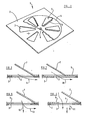
- a diffuser I in accordance with the present invention is illustrated.
- the diffuser shown is intended to be mounted on a ceiling and thus has the same exterior configuration as a ceiling tile so that the diffuser may readily be mounted in position in an array of ceiling tiles.
- the diffuser comprises a lower plate 2 which may be formed of any suitable material, and the plate has formed therein a plurality of apertures 3.
- the illustrated apertures are of substantially triangular configuration, and the apertures are radially arranged about a centre point to resemble the petals of a flower.
- the area of the spaces 4 left between adjacent apertures 3 is at least as great each of the apertures. Any convenient number of apertures may be provided.
- a closure plate 5 is provided which is located above the plate 2.
- the closure plate 5 is, in the embodiment illustrated, a circular plate which is provided with a plurality of apertures 6 corresponding substantially precisely with the aperture- 3 formed in the plate 2.
- each aperture 6 is provided with an inclined flange 7, which extends upwardly and angularly from one of the longer side edges of the triangular aperture 6.
- the flanges 7 are all arranged symmetrically on a consistant side edge of each of the apertures.
- the closure plate 5 is rotatably and adjustably connected to the plate 2 by means of an appropriate boss 8, located at said centre point and the arrangement is such that by applying a screw driver or the like the part of the boss 8 exposed on the underside of the lower plate 2 the closure plate 5 may be rotated from the exposed face of the diffuser 2.
- the diffuser as described above is intended for mounting in a position on a ceiling with a ventilation duct terminating immediately above the closure plate 5, and supplying air under a slight pressure to the space beneath the ceiling.
- closure plate 5 can be moved to a position in which the apertures 6 present in the closure plate 5 are precisely aligned with the apertures 3 present in the plate 2. This is the condition that is schematically illustrated in Figure 2 of the accompanying drawings. It will be appreciated that with the apparatus in this condition the inclined flange 7 will extend from a position within the chamber defined above the diffuser to terminate immediately adjacent one side edge of the aperture 3 formed in the plate 2. In such a condition air from the ventilation duct that terminates above the diffuser will flow down through the aperture 3, and will be guided by the flange 7.
- the stream of air will tend to become entrained against the lower surface of the plate 2, and will also be substantially entrained against the ceiling-to flow across the ceiling of the room in which the diffuser is mounted as indicated schematically by the arrow 9.
- the various streams of air emanating from the various apertures present in the described diffuser will cooperatively interfere with one another (since, due to the radial arrangement of the apertures the streams of air will at least partially cross each other) to provide a gently turbulant pattern of air flow which will be substantially entrained across the ceiling of a room. This will generate a general upflow of air from the room beneath the diffuser and the end result is a general circulation of air within the room without the creation of any violent droughts.
- the closure plate 5 may be rotated by a small amount to have the position as illustrated in Figure 3.
- the apertures 3 are partly closed, and the part of the flange 7 that is connected to the closure plate 5 is located substantially centrally of the aperture 3.
- the result is that the effective size of the aperture 3 is . reduced, and thus a smaller quantity of air will flow through the aperture.
- the air will still be directed by the flange 7 and by virtue of the coanda effect the air will still tend to adhere to the flush surface of the plate 2 and the surface of the adjacent portions of the ceiling as indicated by means of the arrow 10.
- a small degree of turbulance may be created as the flow passes the periphery of the aperture 3.
- closure plate 5 If the closure plate 5 is rotated further in the same sense a condition will exist in which the apertures 6 in the closure plate 5 are totally misaligned with the apertures 3 in the plate 2, and the diffuser will then be closed preventing the flow of air through the diffuser.
- the effective size of the aperture 3 is increased, thus increasing the flow of air through the aperture, and the point of connection of the flange 7 to the closure plate 5 is brought closer to the edge of the aperture 3.
- the flange 7 has an increasing effect, and in this position, whilst some air will flow out of the aperture and continue to flow downwardly, os indicated by the arrows 12, some air, as indicated by the : arrow 13 will, by virtue of the coanda effect cling to the underside of the plate 2.
- closure plate may be formed from a material haying a matt black finish to improve the aesthetic appearance of the diffuser.
- closure plate Whilst the invention has been described with reference to an embodiment in which the closure plate is intended to be rotated to be moved into the various positions described, it is to be understood that in alternative embodiments of the invention the closure plate may be adapted to slide longitudinally between operative positions corresponding to those described above. In such an embodiment the various apertures would be laterally extending apertures, rather than radially extending apertures as in the present embodiment.
- the invention has been described in terms of a diffuser for use with a duct supply air to a space to be ventilated it would be possible, for aesthetic reasons, to mount corresponding diffusers on exhaust ducts. Also, whilst the description given above indicates that the diffusers may be ceiling mounted, the diffusers may also be wall mounted, or may be "free standing" (i.e. hanging freely) when a larger lower plate 2 would be utilised to promote the coander effect in the absence of a suitable adjacent surface.
Landscapes
- Engineering & Computer Science (AREA)
- Chemical & Material Sciences (AREA)
- Combustion & Propulsion (AREA)
- Mechanical Engineering (AREA)
- General Engineering & Computer Science (AREA)
- Aeration Devices For Treatment Of Activated Polluted Sludge (AREA)
- Duct Arrangements (AREA)
Applications Claiming Priority (2)
| Application Number | Priority Date | Filing Date | Title |
|---|---|---|---|
| GB838316716A GB8316716D0 (en) | 1983-06-20 | 1983-06-20 | Diffuser |
| GB8316716 | 1983-06-20 |
Publications (2)
| Publication Number | Publication Date |
|---|---|
| EP0129000A2 true EP0129000A2 (de) | 1984-12-27 |
| EP0129000A3 EP0129000A3 (de) | 1986-04-30 |
Family
ID=10544488
Family Applications (1)
| Application Number | Title | Priority Date | Filing Date |
|---|---|---|---|
| EP84101583A Ceased EP0129000A3 (de) | 1983-06-20 | 1984-02-16 | Luftverteiler |
Country Status (2)
| Country | Link |
|---|---|
| EP (1) | EP0129000A3 (de) |
| GB (1) | GB8316716D0 (de) |
Cited By (13)
| Publication number | Priority date | Publication date | Assignee | Title |
|---|---|---|---|---|
| EP0211150A3 (en) * | 1985-07-27 | 1987-05-27 | Schako Metallwarenfabrik Ferdinand Schad Kg | Outlet with vortex flow |
| EP0414022A3 (en) * | 1989-08-23 | 1992-02-26 | H. Krantz Gmbh & Co. | Outlet with a vortex flow |
| EP0439736A3 (en) * | 1990-02-02 | 1992-03-04 | Fritz Juergen Eidmann | Air outlet, especially ceiling air outlet |
| US5120274A (en) * | 1988-03-18 | 1992-06-09 | Schako Metallwarenfabrik Ferdinand Schad Kg | Ceiling outlet |
| DE19912567A1 (de) * | 1999-03-19 | 2000-10-12 | Werner Wildeboer | Luftleiteinrichtung für einen Luftdurchlaß |
| EP1099914A1 (de) * | 1999-11-10 | 2001-05-16 | LTG Aktiengesellschaft | Luftauslass |
| NL1030021C2 (nl) * | 2005-09-23 | 2007-03-26 | Nijburg Invest B V | Ventilatierooster. |
| DE102007039306A1 (de) * | 2007-08-10 | 2009-02-12 | Ltg Aktiengesellschaft | Luftauslass |
| FR2962795A1 (fr) * | 2010-07-15 | 2012-01-20 | Christian Barbarin | Bouche de ventilation |
| FR2968024A1 (fr) * | 2010-11-29 | 2012-06-01 | Said Riviere | Dispositif d'assemblage de modules prefabriques et structure de modules prefabriques correspondant |
| EP4224077A1 (de) * | 2022-02-03 | 2023-08-09 | Krantz GmbH | Luftdurchlass |
| EP4249820A1 (de) * | 2022-03-22 | 2023-09-27 | LTG Aktiengesellschaft | Raumluftverteilerkasten zur belüftung oder klimatisierung von räumen |
| WO2024150045A1 (en) | 2023-01-09 | 2024-07-18 | Uab "Ventmann" | Air diffuser |
Family Cites Families (3)
| Publication number | Priority date | Publication date | Assignee | Title |
|---|---|---|---|---|
| US2381345A (en) * | 1942-06-05 | 1945-08-07 | Alfred L Greenlaw | Grill |
| US2672087A (en) * | 1950-05-16 | 1954-03-16 | Aladdin Heating Corp | Air distributing device |
| FR1102834A (fr) * | 1954-06-23 | 1955-10-26 | Perfectionnements apportés aux diffuseurs d'air |
-
1983
- 1983-06-20 GB GB838316716A patent/GB8316716D0/en active Pending
-
1984
- 1984-02-16 EP EP84101583A patent/EP0129000A3/de not_active Ceased
Cited By (19)
| Publication number | Priority date | Publication date | Assignee | Title |
|---|---|---|---|---|
| EP0211150A3 (en) * | 1985-07-27 | 1987-05-27 | Schako Metallwarenfabrik Ferdinand Schad Kg | Outlet with vortex flow |
| US5120274A (en) * | 1988-03-18 | 1992-06-09 | Schako Metallwarenfabrik Ferdinand Schad Kg | Ceiling outlet |
| EP0414022A3 (en) * | 1989-08-23 | 1992-02-26 | H. Krantz Gmbh & Co. | Outlet with a vortex flow |
| EP0439736A3 (en) * | 1990-02-02 | 1992-03-04 | Fritz Juergen Eidmann | Air outlet, especially ceiling air outlet |
| DE19912567A1 (de) * | 1999-03-19 | 2000-10-12 | Werner Wildeboer | Luftleiteinrichtung für einen Luftdurchlaß |
| DE19912567B4 (de) * | 1999-03-19 | 2006-08-10 | Werner Dipl.-Ing. Wildeboer | Luftleiteinrichtung für einen Luftdurchlaß |
| EP1099914A1 (de) * | 1999-11-10 | 2001-05-16 | LTG Aktiengesellschaft | Luftauslass |
| DE19954162C1 (de) * | 1999-11-10 | 2001-06-28 | Ltg Ag | Luftauslass |
| NL1030021C2 (nl) * | 2005-09-23 | 2007-03-26 | Nijburg Invest B V | Ventilatierooster. |
| EP1767877A3 (de) * | 2005-09-23 | 2010-07-07 | Nijburg Investment B.V. | Lüftungsrost |
| DE102007039306A1 (de) * | 2007-08-10 | 2009-02-12 | Ltg Aktiengesellschaft | Luftauslass |
| EP2023053A3 (de) * | 2007-08-10 | 2013-02-20 | LTG Aktiengesellschaft | Luftauslass |
| DE102007039306B4 (de) * | 2007-08-10 | 2014-05-15 | Ltg Aktiengesellschaft | Luftauslass |
| FR2962795A1 (fr) * | 2010-07-15 | 2012-01-20 | Christian Barbarin | Bouche de ventilation |
| FR2968024A1 (fr) * | 2010-11-29 | 2012-06-01 | Said Riviere | Dispositif d'assemblage de modules prefabriques et structure de modules prefabriques correspondant |
| EP4224077A1 (de) * | 2022-02-03 | 2023-08-09 | Krantz GmbH | Luftdurchlass |
| EP4249820A1 (de) * | 2022-03-22 | 2023-09-27 | LTG Aktiengesellschaft | Raumluftverteilerkasten zur belüftung oder klimatisierung von räumen |
| WO2024150045A1 (en) | 2023-01-09 | 2024-07-18 | Uab "Ventmann" | Air diffuser |
| LT7086B (lt) | 2023-01-09 | 2024-08-26 | Uab "Ventmann" | Oro difuzorius |
Also Published As
| Publication number | Publication date |
|---|---|
| EP0129000A3 (de) | 1986-04-30 |
| GB8316716D0 (en) | 1983-07-20 |
Similar Documents
| Publication | Publication Date | Title |
|---|---|---|
| EP0129000A2 (de) | Luftverteiler | |
| US5501634A (en) | Air conditioner cover assembly | |
| US3699872A (en) | Air distribution apparatus | |
| US4665806A (en) | Ventilating air distributor | |
| US4061082A (en) | Ventilating air filtering and distributing device | |
| JPS62268950A (ja) | 吹出口からの気流をそらせるための装置 | |
| US20080176506A1 (en) | Fabric diffuser with programmed airflow | |
| PT82694A (fr) | Dispositif d'aeration des locaux et de tirage des cheminees | |
| US6800024B1 (en) | Vent termination receptacle with damper | |
| EP1310743A4 (de) | Dekorative platte und luftverteiler für klimaanlage und klimaanlage | |
| US4100938A (en) | Flow control unit for air distribution system | |
| JPH05505020A (ja) | 室内に空気を導くためのエアーノズル | |
| GB1595946A (en) | Air distributing apparatus | |
| US3673946A (en) | Air diffuser | |
| US2433981A (en) | Ventilating air distributor | |
| US4475446A (en) | High volume ceiling type air diffuser | |
| JP4636671B2 (ja) | 吹出口 | |
| JPS5926191Y2 (ja) | 車両用空気調整装置 | |
| US2923224A (en) | Air distributor | |
| US3703140A (en) | Ceiling air terminal | |
| US3901135A (en) | Device for distributing ventilating air | |
| US2891461A (en) | Directional control air diffuser | |
| GB2221530A (en) | Improvements in or relating to air diffusers | |
| US2881689A (en) | Air distribution means | |
| JP2633328B2 (ja) | 風向変更装置 |
Legal Events
| Date | Code | Title | Description |
|---|---|---|---|
| PUAI | Public reference made under article 153(3) epc to a published international application that has entered the european phase |
Free format text: ORIGINAL CODE: 0009012 |
|
| AK | Designated contracting states |
Designated state(s): AT BE CH DE GB LI LU NL |
|
| RAP1 | Party data changed (applicant data changed or rights of an application transferred) |
Owner name: WATERLOO GRILLE CO. LTD. Owner name: WATERLOO B.V. |
|
| RAP1 | Party data changed (applicant data changed or rights of an application transferred) |
Owner name: WATERLOO GRILLE CO. LTD. Owner name: WATERLOO B.V. |
|
| PUAL | Search report despatched |
Free format text: ORIGINAL CODE: 0009013 |
|
| AK | Designated contracting states |
Kind code of ref document: A3 Designated state(s): AT BE CH DE GB LI LU NL |
|
| 17P | Request for examination filed |
Effective date: 19860423 |
|
| 17Q | First examination report despatched |
Effective date: 19860829 |
|
| STAA | Information on the status of an ep patent application or granted ep patent |
Free format text: STATUS: THE APPLICATION HAS BEEN REFUSED |
|
| 18R | Application refused |
Effective date: 19870813 |
|
| RIN1 | Information on inventor provided before grant (corrected) |
Inventor name: LYALL, ALAN COLIN |