EP0129004B1 - Ensemble compresseur - Google Patents
Ensemble compresseur Download PDFInfo
- Publication number
- EP0129004B1 EP0129004B1 EP84103237A EP84103237A EP0129004B1 EP 0129004 B1 EP0129004 B1 EP 0129004B1 EP 84103237 A EP84103237 A EP 84103237A EP 84103237 A EP84103237 A EP 84103237A EP 0129004 B1 EP0129004 B1 EP 0129004B1
- Authority
- EP
- European Patent Office
- Prior art keywords
- compressor
- pressure
- volume
- valve
- compressed air
- Prior art date
- Legal status (The legal status is an assumption and is not a legal conclusion. Google has not performed a legal analysis and makes no representation as to the accuracy of the status listed.)
- Expired
Links
- 230000006835 compression Effects 0.000 claims description 2
- 238000007906 compression Methods 0.000 claims description 2
- 238000001816 cooling Methods 0.000 claims description 2
- 238000002347 injection Methods 0.000 claims description 2
- 239000007924 injection Substances 0.000 claims description 2
- 238000005461 lubrication Methods 0.000 claims description 2
- 230000001105 regulatory effect Effects 0.000 claims description 2
- 238000000926 separation method Methods 0.000 claims 1
- 238000000605 extraction Methods 0.000 description 9
- 238000010276 construction Methods 0.000 description 3
- 238000005192 partition Methods 0.000 description 2
- XLYOFNOQVPJJNP-UHFFFAOYSA-N water Substances O XLYOFNOQVPJJNP-UHFFFAOYSA-N 0.000 description 2
- 230000007423 decrease Effects 0.000 description 1
- 238000010586 diagram Methods 0.000 description 1
- 239000002283 diesel fuel Substances 0.000 description 1
- 239000000446 fuel Substances 0.000 description 1
- 210000004072 lung Anatomy 0.000 description 1
- 238000011144 upstream manufacturing Methods 0.000 description 1
- 238000009423 ventilation Methods 0.000 description 1
- 238000013022 venting Methods 0.000 description 1
Images

Classifications
-
- F—MECHANICAL ENGINEERING; LIGHTING; HEATING; WEAPONS; BLASTING
- F04—POSITIVE - DISPLACEMENT MACHINES FOR LIQUIDS; PUMPS FOR LIQUIDS OR ELASTIC FLUIDS
- F04C—ROTARY-PISTON, OR OSCILLATING-PISTON, POSITIVE-DISPLACEMENT MACHINES FOR LIQUIDS; ROTARY-PISTON, OR OSCILLATING-PISTON, POSITIVE-DISPLACEMENT PUMPS
- F04C28/00—Control of, monitoring of, or safety arrangements for, pumps or pumping installations specially adapted for elastic fluids
- F04C28/06—Control of, monitoring of, or safety arrangements for, pumps or pumping installations specially adapted for elastic fluids specially adapted for stopping, starting, idling or no-load operation
Definitions
- the invention relates to a compressor system with a compressor, in particular a screw compressor, with oil injection into the compression chamber for lubrication and cooling and an oil separating and collecting container connected downstream of the compressor.
- Such a compressor system with a vane compressor is known from GB-A 2 020 362.
- the compressed air mixed with oil which emerges from the compressor, flows through an oil separating and collecting container and then reaches a downstream oil separating chamber in which an oil separating cartridge is arranged.
- a pressure line leads from the oil separator chamber to the consumer, in which a non-return valve and an automatic separator for condensed water and any oil still present are provided, condensed water and oil being automatically removed from the separator when a predetermined level is reached.
- Transportable compressor systems such as those used to supply compressed air consumers, for example on construction sites, have no storage volume for the compressed air because they should be small and light. Rather, only the hose length between the consumer, for example a jackhammer, and the compressor system is available as a storage volume. If the compressor were switched to relieved idle when the consumer was switched off, for example when a pneumatic hammer was stopped, then compressed air would not be immediately available when the pneumatic hammer was switched on again, because the oil separator and collecting container is vented when the idle is relieved and nothing else Storage volume for compressed air is available. The consumer would have to wait until the compressor delivers sufficient compressed air again.
- the unloaded idle of the compressor which also accounts for a significant proportion of the total running time, for example about half of the total running time, wastes considerable drive energy, be it electrical drive energy or diesel fuel in diesel-powered systems.
- This disadvantage could be remedied by a correspondingly large compressed air boiler, which stores sufficient compressed air when the consumer is switched off, which is immediately available when the consumer is switched on again and is sufficient until the compressor has switched from idling to load and supplies sufficient compressed air again.
- a compressed air boiler is voluminous and heavy and stands in the way of a lightweight and small compressor system.
- the invention has for its object to provide a compressor system of the type specified in such a way that it can be switched to the relieved idle when the consumer is switched off and when the consumer is switched on again without additional compressed air boiler, sufficient compressed air is available which meets the requirements until the compressed air supplies are reinstated covered by the compressor.
- the compressor Due to the specified distribution of the already existing oil separating and collecting container, the compressor can be relieved to zero by venting the one part of the container while idling, while the other part of the container, which is still under pressure, creates a compressed air reservoir, which above all serves as a control volume for switching the Compressor can be used from the unloaded idle to load. In this way, it is possible to reduce the drive energy of the compressor, which is 70% of the drive energy customarily used during operation, to 20% of the unloaded idle. Taking into account the length of the idle time, this results in a considerable saving in drive energy or fuel.
- Fig. 1 denotes a screw compressor, in the intake line 2 of which a volume flow controller 4 is continuously adjustable by a control cylinder 3 is arranged. 5 with an intake air filter is designated.
- the screw compressor 1 supplies compressed air mixed with oil via line 6 into a first volume or an oil separating and collecting container 7, in which the main amount of oil separates from the compressed air by impact or deflection and is collected.
- This first volume 7 is followed by a second volume 9 via a check valve 8, in which a separating cartridge 10 is arranged.
- a compressed air extraction line 11 leads to one or more consumers 12.
- a 13 denotes a minimum pressure valve in the compressed air extraction line 11, whose spring-loaded valve body 14 shuts off the extraction line when the consumer 12 is switched off and moves into the open position when the consumer , for example a jackhammer, is switched on again.
- a bore 15 is provided in the minimum pressure valve 13, through which the final pressure built up by the compressor 1 is removed.
- These Bore 15 is connected via a line 16 to a known proportional pressure regulator 17, which acts on the piston of the regulating cylinder 3 on the spring-loaded side with compressed air such that the volume flow regulator 4 is continuously adjusted in accordance with the compressed air requirement.
- a line 18 Via a line 18, the final pressure is applied to a solenoid valve 19 which is adjusted by a spring 20 when it is switched off.
- the final pressure of the compressor is applied via a line 21 to a control valve 22, which is switched over by a spring 23 when the pressure in the line 21 drops below a certain value.
- a vent line 24 leading away from the volume or container 7 is shut off, while an oil suction line 25 leading away from the container 9 is connected to the suction area of the compressor 1 via a check valve.
- the ventilation line 24 is connected to a line 27 which opens into the intake line 2 upstream of the volume flow regulator 4.
- the oil suction line 25 is shut off at 40 in this switch position.
- the final pressure supplied by line 18 is applied via solenoid valve 19, further via line 29 provided with a throttle 28, to a pressure switch 30 which is connected to line 31 between proportional pressure regulator 17 and control cylinder 3.
- a line 32 branching off from the suction line 2 behind the volume flow regulator 4 is connected via a line 33 to the control cylinder 3 in such a way that the pressure of the suction line 2 acts on the piston on the side opposite the spring.
- the lines 21, 29 are vented at 34, while the line 33 leading to the control cylinder 3 is connected to the line 18 in which the final pressure of the compressor is present.
- An oil main line 35 leads from the oil reservoir in the container 7 to the suction area of the compressor 1. Further components, such as flow regulators, oil coolers, drive motors and the like, which are present in a compressor system of this type, are not shown, since they are used to explain the invention are not required.
- the electrical circuit of the solenoid valve 19 is not shown to simplify the illustration, it is clear from the following description of the functional sequence.
- the solenoid valve 19 is electrically connected to the pressure switch 30 and to a transmitter 36 which scans the position of the valve body 14 on the minimum pressure valve 13.
- the compressor system works as follows. Are located in the illustrated switching position, the valves 19 and 22 in the Anfahrentlastun g sstel- lung.
- the volume flow controller 4 is closed by the spring in the control cylinder 3.
- the screw compressor 1 is driven, whereupon the solenoid valve 19 is switched from the position shown after a predetermined time, the left side of the piston in the control cylinder 3 being vented and the other side with the building up Pressure is applied in the compressed air extraction line 11 so that the volume flow controller 4 can be moved into the open position.
- the piston in the control cylinder is continuously adjusted in accordance with the characteristic curve of the proportional pressure regulator 17.
- the control valve 22 remains in the switch position shown, in which the remaining oil still separated in the second separating tank 9 is sucked off via the lines 25, 26 and oil is injected via the main oil line 35 from the first separating tank 7 into the screw compressor 1, which is under the pressure supplied by the compressor.
- the minimum pressure valve 13 equipped with a check function closes the compressed air extraction line 11.
- a minimum pressure valve is described in GM 80 50 773.
- the final pressure built up by the compressor 1 in the extraction line rises and is supplied via the proportional pressure regulator 17, which acts as a pressure booster, to the pressure switch 30, which responds with a predetermined time delay and switches the solenoid valve 19 into the position shown.
- the control cylinder is connected to the intake line 2 on the right-hand side of the piston, so that the volume flow controller is moved into the closed position by the force of the spring and the applied final pressure.
- the increased final pressure of the compressor is applied to the control valve 22 via the lines 18, 21, which is switched over so that the first separating tank 7 is vented via the line 27 and the oil suction line 25 coming from the second separating tank 9 is shut off.
- the screw compressor 1 is thus completely relieved, it only works against the zero pressure level in the first separating container 7, only the rotors of the screw compressor 1 being rotated by the drive motor with a drive power of approximately 20%.
- the second volume 9 is encapsulated by the check valve 8 and the shut-off minimum pressure valve 13 and can thus serve as a compressed air reservoir.
- the line 29 is connected to the line 18, the final pressure at the pressure switch 30 which can hold the pressure switch 30 stable in the switching position can be built up via the throttle 28.
- the time-delayed response of the pressure switch 30 ensures that the compressor 1 is not switched to the unloaded idle in the event of brief interruptions in the compressed air extraction by the consumer 12.
- a switch (not shown) can be provided, which disconnects the automatic switchover to the idle state, so that even when the Un interruption of the compressed air extraction the compressor can run in unloaded idle.
- the electrical circuit is designed such that the transmitter 36 is ineffective as long as there is no signal from the pressure switch 30 for the switching of the solenoid valve 19 into the switching position shown for the relieved idling. However, as soon as this signal is present and the solenoid valve 19 is switched, the transmitter 36 is given priority, so that when the valve body 14 moves into the open position, a signal generated by the transmitter 36 immediately switches the solenoid valve 19 back without a further signal from the pressure switch 30 .
- the valve body 14 of the minimum pressure valve 13 with a check function is first moved into the open position, the transmitter 36 emitting a signal for switching the solenoid valve 19.
- the line 21 is vented via 34, so that the control valve 22 is switched back into the switching position shown by the spring 23.
- the pressure of the pressure accumulator 9 comes into contact with the control cylinder 3 via the lines 18, 33, as a result of which the volume flow regulator 4 is moved into the open position.
- the screw compressor 1 thus switched over to load delivers compressed air into the second container 9 via the first separating container 7 before the pressure in this pressure accumulator has dropped significantly due to the renewed removal of the consumer 12.
- the compressed air reservoir 9 also serves as a control volume for switching the control valve 22 and for acting on the control cylinder 3.
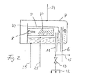
- FIG. 2 shows a different container division, the same reference numerals as in FIG. 1 being used for the same or corresponding components.
- the second volume 9 serving as a pressure accumulator is arranged within the first separating and collecting container 7, the check valve 8 being installed in the container 9.
- a vertical partition 37 is arranged in the container 7, which ends at a distance from the upper container wall. The air entering through the line 6, mixed with oil, flows after separating the oil in the container 7 over the upper edge of this partition 37 and passes through the check valve 8 into the separating cartridge 10. At the mouth of the extraction line 11, clean air emerges.
- the lines 24, 25 and 35 already described in connection with FIG. 1 are also connected to the two containers. In unloaded idling, there is, for example, a pressure of 0 bar in container 7 and 7 bar in container 9.
- the containers built into each other can also be arranged vertically.
- a manually adjustable proportional pressure regulator 17 is provided, by means of which the pressure can be set at which the pressure switch 30 responds.
- the pressure switch 30 can remain set to a fixed value.
- the proportional pressure regulator 17 has a structure which is known per se, each change in the pressure at the inlet causing an increased change in the pressure at the outlet of the regulator.
- the arrangement of the container division described in FIG. 2 is also particularly suitable for a compact design of a compressor, as described in DE-OS 2 938 557.
- the transmitter 36 can be a contactless transmitter or a limit switch acted upon by the valve body.
Landscapes
- Engineering & Computer Science (AREA)
- Mechanical Engineering (AREA)
- General Engineering & Computer Science (AREA)
- Applications Or Details Of Rotary Compressors (AREA)
Claims (6)
Applications Claiming Priority (2)
| Application Number | Priority Date | Filing Date | Title |
|---|---|---|---|
| DE19833311055 DE3311055A1 (de) | 1983-03-25 | 1983-03-25 | Verdichteranlage |
| DE3311055 | 1983-03-25 |
Publications (2)
| Publication Number | Publication Date |
|---|---|
| EP0129004A1 EP0129004A1 (fr) | 1984-12-27 |
| EP0129004B1 true EP0129004B1 (fr) | 1988-08-24 |
Family
ID=6194744
Family Applications (1)
| Application Number | Title | Priority Date | Filing Date |
|---|---|---|---|
| EP84103237A Expired EP0129004B1 (fr) | 1983-03-25 | 1984-03-23 | Ensemble compresseur |
Country Status (2)
| Country | Link |
|---|---|
| EP (1) | EP0129004B1 (fr) |
| DE (2) | DE3311055A1 (fr) |
Families Citing this family (3)
| Publication number | Priority date | Publication date | Assignee | Title |
|---|---|---|---|---|
| DE4118644A1 (de) * | 1991-06-04 | 1992-12-10 | Mannesmann Ag | Vorrichtung zur regelung der liefermenge eines oelgeschmierten verdichters |
| AUPP202198A0 (en) * | 1998-02-25 | 1998-03-19 | Cash Engineering Research Pty Ltd | Oil cooler and separator assembly |
| KR20190057346A (ko) | 2016-09-21 | 2019-05-28 | 크노르-브렘제 시스테메 퓌어 누츠파조이게 게엠베하 | 차량, 특히 상용차용 스크루 압축기를 위한 최소 압력 밸브 |
Family Cites Families (5)
| Publication number | Priority date | Publication date | Assignee | Title |
|---|---|---|---|---|
| AT191065B (de) * | 1954-03-25 | 1957-08-10 | Worthington Corp | Einrichtung zum Erwärmen und Kühlen des Schmiermittels bei Rotationskompressoren |
| GB2020362A (en) * | 1978-03-13 | 1979-11-14 | Imi Fluidair Ltd | Rotary compressor |
| DE2821321A1 (de) * | 1978-05-16 | 1979-11-22 | Ruediger Dr Ing Klein | Vorrichtung zur erzeugung von druckluft |
| DE2846005A1 (de) * | 1978-10-23 | 1980-04-30 | Bauer Heinz | Rotations- bzw. drehkolbenverdichteranlage mit oelkreislauf und absperrorganen |
| DE2938557A1 (de) * | 1979-09-24 | 1981-04-23 | Isartaler Schraubenkompressoren Gmbh, 8192 Gertsried | Verdichteranlage |
-
1983
- 1983-03-25 DE DE19833311055 patent/DE3311055A1/de not_active Withdrawn
-
1984
- 1984-03-23 DE DE8484103237T patent/DE3473627D1/de not_active Expired
- 1984-03-23 EP EP84103237A patent/EP0129004B1/fr not_active Expired
Also Published As
| Publication number | Publication date |
|---|---|
| EP0129004A1 (fr) | 1984-12-27 |
| DE3473627D1 (en) | 1988-09-29 |
| DE3311055A1 (de) | 1984-10-11 |
Similar Documents
| Publication | Publication Date | Title |
|---|---|---|
| EP1037759B1 (fr) | Dispositif pour refouler du carburant depuis un reservoir jusqu'au moteur a combustion interne d'un vehicule automobile | |
| DE1403453A1 (de) | Verbesserungen an Kompressor-Aggregaten | |
| DE3718607A1 (de) | Kraftstoffeinspritzpumpenanordnung | |
| AT401551B (de) | Vorrichtung zur druckabsenkung eines verdichters | |
| EP1566536A1 (fr) | Système d'alimentation en carburant et procédé de contrôle de l'alimentation en carburant | |
| DE2325992A1 (de) | Vorrichtung zur steuerung eines hydraulischen motors | |
| DE3781770T2 (de) | Schnellen druck aufbauende tauchkolbenpumpe. | |
| DE3247004C2 (de) | Hydrostatisches Getriebe, insbesondere für den Fahrzeugantrieb | |
| DE10003748A1 (de) | Kraftstoffversorgungssystem für Brennkraftmaschinen mit verbesserter Befüllung der Kraftstoffleitung | |
| EP0084085B1 (fr) | Pompe à vide avec une soupape dans la tubulure d'aspiration et son procédé de mise en activité | |
| EP0129004A1 (fr) | Ensemble compresseur | |
| DE19654781A1 (de) | Hilfseinrichtung zur Realisierung einer Redundanz für die Energieversorgung von Flugsteuerungsantrieben | |
| DE102012212892B4 (de) | Einspritzeinrichtung für eine Verbrennungskraftmaschine | |
| DE102013014291A1 (de) | Kraftstoff-Fördersystem und Versorgungssystem, insbesondere für den Einsatz in dahingehenden Kraftstoff-Fördersystemen | |
| EP0094590A2 (fr) | Installation dans laquelle un réfrigérant est circulé | |
| EP0440845B1 (fr) | Système de distribution pour carburants liquides | |
| WO1995025653A1 (fr) | Systeme de freinage hydraulique a regulation antipatinage et antiblocage | |
| DE659106C (de) | Einrichtung an einer Pumpenanlage, insbesondere Schoepfwerksanlage | |
| DE2951305A1 (de) | Drucklufterzeugungsanlage | |
| DE3814368C1 (en) | System for supplying oil to a rotary piston compressor cooled by oil injection | |
| DE9104511U1 (de) | Vorrichtung zum Fördern von Kraftstoff aus einem Vorratstank zur Brennkraftmaschine eines Kraftfahrzeugs | |
| DE19621167A1 (de) | Luftabscheider für einen Milchsammelwagen | |
| DE4118644C2 (fr) | ||
| DE2951304A1 (de) | Drucklufterzeugungsanlage | |
| DE1915174A1 (de) | Verfahren und Vorrichtung zum automatischen Verdichteroelspiegelausgleich in mehrere Kaeltemittelverdichter mit eingebauten Schmieroelpumpen umfassenden Kaelteanlagen |
Legal Events
| Date | Code | Title | Description |
|---|---|---|---|
| PUAI | Public reference made under article 153(3) epc to a published international application that has entered the european phase |
Free format text: ORIGINAL CODE: 0009012 |
|
| AK | Designated contracting states |
Designated state(s): BE DE FR GB IT SE |
|
| 17P | Request for examination filed |
Effective date: 19850627 |
|
| 17Q | First examination report despatched |
Effective date: 19860616 |
|
| D17Q | First examination report despatched (deleted) | ||
| GRAA | (expected) grant |
Free format text: ORIGINAL CODE: 0009210 |
|
| AK | Designated contracting states |
Kind code of ref document: B1 Designated state(s): BE DE FR GB IT SE |
|
| ITF | It: translation for a ep patent filed | ||
| REF | Corresponds to: |
Ref document number: 3473627 Country of ref document: DE Date of ref document: 19880929 |
|
| GBT | Gb: translation of ep patent filed (gb section 77(6)(a)/1977) | ||
| ET | Fr: translation filed | ||
| PGFP | Annual fee paid to national office [announced via postgrant information from national office to epo] |
Ref country code: FR Payment date: 19890222 Year of fee payment: 6 |
|
| PGFP | Annual fee paid to national office [announced via postgrant information from national office to epo] |
Ref country code: SE Payment date: 19890224 Year of fee payment: 6 Ref country code: DE Payment date: 19890224 Year of fee payment: 6 Ref country code: BE Payment date: 19890224 Year of fee payment: 6 |
|
| PGFP | Annual fee paid to national office [announced via postgrant information from national office to epo] |
Ref country code: GB Payment date: 19890228 Year of fee payment: 6 |
|
| ITTA | It: last paid annual fee | ||
| PLBE | No opposition filed within time limit |
Free format text: ORIGINAL CODE: 0009261 |
|
| STAA | Information on the status of an ep patent application or granted ep patent |
Free format text: STATUS: NO OPPOSITION FILED WITHIN TIME LIMIT |
|
| 26N | No opposition filed | ||
| PG25 | Lapsed in a contracting state [announced via postgrant information from national office to epo] |
Ref country code: GB Effective date: 19900323 |
|
| PG25 | Lapsed in a contracting state [announced via postgrant information from national office to epo] |
Ref country code: SE Effective date: 19900324 |
|
| PG25 | Lapsed in a contracting state [announced via postgrant information from national office to epo] |
Ref country code: BE Effective date: 19900331 |
|
| BERE | Be: lapsed |
Owner name: ISARTALER SCHRAUBENKOMPRESSOREN G.M.B.H. Effective date: 19900331 |
|
| GBPC | Gb: european patent ceased through non-payment of renewal fee | ||
| PG25 | Lapsed in a contracting state [announced via postgrant information from national office to epo] |
Ref country code: FR Effective date: 19901130 |
|
| PG25 | Lapsed in a contracting state [announced via postgrant information from national office to epo] |
Ref country code: DE Effective date: 19901201 |
|
| REG | Reference to a national code |
Ref country code: FR Ref legal event code: ST |
|
| EUG | Se: european patent has lapsed |
Ref document number: 84103237.8 Effective date: 19910110 |