EP0129062A2 - Système de mesure à laser pour la mesure des procédés de serrage et d'alignement à des machines-outils et pour la mesure de vibration - Google Patents
Système de mesure à laser pour la mesure des procédés de serrage et d'alignement à des machines-outils et pour la mesure de vibration Download PDFInfo
- Publication number
- EP0129062A2 EP0129062A2 EP84105561A EP84105561A EP0129062A2 EP 0129062 A2 EP0129062 A2 EP 0129062A2 EP 84105561 A EP84105561 A EP 84105561A EP 84105561 A EP84105561 A EP 84105561A EP 0129062 A2 EP0129062 A2 EP 0129062A2
- Authority
- EP
- European Patent Office
- Prior art keywords
- laser
- measuring
- measurement system
- clamping
- rail
- Prior art date
- Legal status (The legal status is an assumption and is not a legal conclusion. Google has not performed a legal analysis and makes no representation as to the accuracy of the status listed.)
- Withdrawn
Links
Images


Classifications
-
- G—PHYSICS
- G01—MEASURING; TESTING
- G01B—MEASURING LENGTH, THICKNESS OR SIMILAR LINEAR DIMENSIONS; MEASURING ANGLES; MEASURING AREAS; MEASURING IRREGULARITIES OF SURFACES OR CONTOURS
- G01B11/00—Measuring arrangements characterised by the use of optical techniques
Definitions
- the invention relates to a laser measuring system, in particular for measuring clamping and straightening processes on machine tools with workpieces of large dimensions, and for vibration measurement on workpieces.
- laser measurement systems are characterized by interferometry and the straightness of the beam spread.
- the use of laser measurement systems outside the laboratory often fails due to the sensitivity of the laser beam to external influences, such as air humidity, temperature and turbulence, which overlap the internal thermal expansion of the mirror system, the laser tube and the positioning accuracy of the deflection elements.
- the high output accuracy of the laser beam can be postponed until it is unusable.
- interferometric measuring methods are mainly used. However, these are not suitable for the usual workshop applications, since in addition to the considerable costs and rough treatment, the surface roughness of most workpieces is greater than the measuring accuracy.
- many measuring processes in the workshop take place in this state, for example clamping and straightening processes on machine tools. Aligning machines of large dimensions and heavy workpieces and taking them up is still work that is time-consuming with inadequate aids.
- the laser measuring system consists of a laser measuring device, a coordinate monitor, a calibration reference, a measuring bed and a deflection adjustment.
- All elements with the exception of the calibration reference are located on a common chassis, in such a way that the laser measuring device can be adjusted at every workstation - ready for use - can be used with one or more fixed coordinate monitors.
- the laser measuring device In the switched-on state, the laser measuring device emits two laser beams, one of which represents the measurement signal and the other laser beam the device zero signal, the two signals being generated from one beam path. This ensures that the relative position of the measurement signal and device zero signal remains fixed, so that the external influences, such as air humidity, temperature and turbulence, shift both signals by the same amount and thus eliminate the deviations as measurement errors.
- the device zero signal is perpendicular to the measuring location and the measuring signal is incident on the measuring location at an acute angle. Angles of approximately 80 ° against the perpendicular - the direction of incidence of the device zero signal - produce a six-fold shift against the device zero signal per unit of the shift in the perpendicular direction.
- the simple readability of the measurement signal which is so important for use in the workshop, is generated either by a very small distance between the traces of the measurement signal and the device zero signal or by a low-frequency modulation of the measurement signal relative to the device zero signal.
- the Gaussian limitation of the laser beam can be canceled on one side by a corresponding design of the deflection unit in the laser measuring device.
- the deflection unit is expediently set so that the width of the measurement signal only slightly exceeds that of the device zero signal.
- Displacements of the center lines of the measurement signal and device zero signal thus lead to an easily recognizable flickering of the boundary of the superimposed signal tracks on the side after which the displacement takes place.
- the measuring accuracy that can be achieved with the unarmed eye, even with eyesight of 30%, is 0.005 mm.
- the use of complementary colors can further increase the resolution for the human eye.
- a further increase in measuring accuracy can be achieved when using optoelectronic sensors.
- Vibration measurements are also made possible by stroposcopic spreading of the device zero signal and measurement signal on the surface of the object to be measured.
- the focus of the laser beams can be changed. If the focusing device of the laser measuring device is actuated in the common beam path for the measuring signal and device zero signal during the measurement and the focus distance is thus changed, measuring distances of several meters in length are to be recorded with constant accuracy. There is no physical limit for the measuring section. It depends solely on the optical elements in the system of the device. With the laser measuring device, precision measurements on long and vibrating components are possible.
- the on-line monitoring of the position of the measurement signal and the device zero signal in relation to the processing plane and thus to the machine tool geometry is achieved by an extremely strong focusing of the measurement signal at a specific location of the machine control.
- High angular rates of change of the measurement signal in the vicinity of this location produce a narrowing of the trace of the measurement signal on the machine tool guide that cannot be achieved by optical means.
- the central value and the immediate vicinity of the energy distributed in the focus in the focus are used as a control signal.
- the focus range decreases by about a power of ten.
- the device thus enables a very precise alignment of workpieces on machine tools in such a way that the surface to be machined and the direction of tool movement are directly coupled to one another via a laser signal.
- the superimposition of the measurement and device zero signal permits machine-integrated use during processing and thus control of the movement sequences and their accuracy.
- the specific location of the machine tool guidance is represented by the coordinate monitor. This records and identifies the collective of disturbance variables from the device structure and external influences.
- the coordinate monitor consists of a rotating body rotatable about the axis of the incident laser beam with two optoelectronic sensors, which use an amplifier to measure two. control devices.
- the sensors are arranged on the center line of the rotating body at the same distance from the center of the rotating body.
- the rotatable device is displaceable laterally to the plane of the incident laser beam.
- the incident energy can be distributed by means of rotation and lateral displacement in such a way that dig-downstream measuring devices indicate coverage when the currents generated by the incident light are equal.
- the starting point of the measuring procedure is determined. If there is a deviation from this position that is only possible laterally, one of the sensors becomes stronger, the other one is irradiated weaker.
- the output on an oscillograph is also possible.
- the effects of collective disturbance variables become quantitatively visible and usable, the correlation of several axes of the laser measuring device in particular ensuring its use over large measuring distances.
- the coordinate monitor should advantageously have an independent power supply. As a result, the measurement is far from the encoder, i.e. away from the laser measuring device, possible under normal conditions.
- the laser measuring device While the laser measuring device is being adjusted, it rests in a defined position on the measuring bed.
- the measuring bed is aligned with the coordinate monitors during the adjustment process.
- the measuring bed has a base plate with three set screws in a triangular arrangement with spring-loaded clamping elements on the lines of action of the clamping triangle, which are arranged on a rail. The rotation of the set screws creates a movement in one of the three spatial coordinate directions and / or a movement. around the other two spatial coordinate directions.
- the rail is advantageously designed as a T-rail with a Morse taper adapter and can be inserted into T-clamping grooves.
- two further set screws Perpendicular to the extension of the rail and the set screws, two further set screws, which come into contact with the rail and are arranged on the base plate, should be provided. These set screws can then be used to move around the first spatial axis mentioned. Any deviation can be corrected by the first three set screws and the two other set screws, since corrections in the direction of the latter two spatial axes are never relevant.
- the tensioning of the T-rail in the T-clamping groove should be caused by spring-loaded balls arranged between the rail and the clamping groove, the spherical caps of which penetrate the flange and the web of the T-rail at their intersection. Such an arrangement causes the parts to be clamped automatically.
- the surface formed by the rotating laser beam is absolutely flat.
- the laser measurement system has a deflection adjustment.
- the deflection unit located in the laser measuring device is adjusted until the calibration reference is covered in full length.
- the adjustment of deflection units the main element of which is a rotating or oscillating mirror, must make it possible to find the boundary between two surface lines, each of which describes a cone on the tip - these against one another - when the surface line is represented by a laser beam.
- the axes of the deflection units are related to one another in spatial coordinates that are not always clearly defined because of the spatial extent of the device.
- the problem of mirror adjustment during the running of the deflection units is advantageously solved in that the deflection adjustment has a device-fixed pivot point, which is the zero point for a translational movement in two axes and a rotational movement in three axes.
- the synchronism between the deflection adjustment and the rotating mirror holder of the deflection unit should be ensured by a friction clutch.
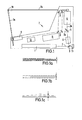
- Fig. 1 the laser measuring device is shown schematically. It has a laser tube 1 inside.
- the laser beam 2 emitted by the laser tube 1 strikes a mirror 3 and is reflected in the direction of a beam expander 4 .
- the expanded beam reaches a beam splitter 5.
- a part 2a of the laser beam 2 is reflected by the beam splitter 5, the other part 2b of the laser beam 2 passes through the beam splitter 5.
- Beam 2a represents the measurement signal, while beam 2b represents the device zero signal.
- the device zero signal is fed to a deflection unit 6 and leaves the laser measuring device in the direction of a vertical plane.
- the measurement signal 2a is reflected by four further mirrors 8 and is likewise fed to a deflection unit 9.
- the measurement signal 2a leaves the deflection unit 9 at an angle of approximately 80 ° to the vertical.
- the intersection line of measuring signal 2a and device zero signal 2b runs perpendicular to the drawing plane through point 10.
- the laser measuring device 7 also has a power supply part 11 and a modulator 12 only indicated schematically in its interior.
- the laser measuring device 7 is also provided with a connection 13, which is provided for accommodating larger beam expansions and crosshair modules. With such additional equipment, it can be used as a construction laser for surface and distance leveling.
- the measuring signal incident by the acute angle is superimposed on the device zero signal incident perpendicularly to the measuring location, for example a workpiece.
- An angle of about 80 ° against the perpendicular - the direction of incidence of the device zero signal - produces a six-fold shift against the device zero signal per unit of the shift in the perpendicular direction. This allows workpieces to be aligned much more precisely on machine tools than before.
- the simple readability of the measurement signal is further generated by a very small distance between the tracks of the measurement signal and the device zero signal, or by a low-frequency modulation of the measurement signal with respect to the device zero signal.
- 1a to 1c show shapes of the intersection traces on workpiece surfaces. 1a shows a laser beam linearized on one side, FIG. 1b the superimposition of the modulated measurement signal with the non-modulated device zero signal and FIG. 1c the superimposition corresponding to FIG. 1b with a workpiece vibration. Between the arrows in FIGS. 1a to 1c, the distances between the tracks of the measurement signal and the device zero signal are shown.
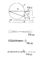
- FIGS. 2, 3 and 4 show the laser measuring device with a workpiece in different views.
- FIG. 2 corresponds to the illustration in FIG. 1, but with the workpiece 14 drawn in.
- FIGS. 3 and 4 illustrate the beam path of the rays 2a and 2b over the workpiece surface.
- 4a, 4b, 4c show the intersection traces on the workpiece surface.
- Fig. 4a shows a gaussian laser beam
- Fig. 4b according to the representation in Fig. 1a a linearized laser beam on one side with the measuring distance indicated between the arrows
- Fig. 4c corresponding to the representation in Fig. 1b superimposed modulated and non-modulated signals also between the arrows arranged measuring distance.
- the on-line monitoring of the position of measuring signal 2a and device zero signal 2b to the machining plane and thus to the machine tool geometry is achieved by an extremely strong focusing of the measuring signal 2a on the machine tool guide in point 16.
- a coordinate monitor to be described in more detail. Due to high angular rates of change.
- Measurement signal 2a at point 16 a narrowing of the track of the measurement signal on the tool guide 17, which cannot be achieved by optical means, is generated. Because of these properties, the laser measuring device 7 enables a very precise alignment of the workpiece 14 on the tool guide 17, since the surface to be machined and the tool movement direction are coupled to one another directly via the measurement signal 2a.
- the measured value can be recorded both by the human eye and simultaneously by optoelectronic means. Line and surface leveling can be made possible by adding devices.
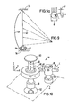
- FIG. 5 shows an overall spatial view of the laser measuring device 7, deflection adjustment 18, coordinate monitors 19 and 20 and measuring bed 21. All elements are located on a common chassis, in such a way that the laser measuring device can be used at any work station, ready for use, with one or more fixed coordinate monitors.
- the laser beams emitted by the laser measuring device 7 sweep over the sensors 24 during the rotation of the deflection unit 6 or 9, which are initially in the center. Because of the finite width of the sensors, the energy distribution in each light guide channel belonging to the sensors is undetermined in this state.
- a state is then set which brings the pointers 29 of the measuring devices 27 and 28 into register. Deviations of the laser beam from this setting then lead to an immediate display by the measuring devices 27 and 28 so that corrections can be made. Can be measured with the laser measuring device with the pointer 29 covered. Measuring devices 27 and 28. Coordinate monitors which are fixed at the work place thus permit the immediate use of the laser measuring device if it has pointer 29 on the chassis covering it.
- FIG. 5 shows in connection with FIG. 7 the arrangement of the laser measuring device 7 on the measuring bed 21 and the means for adjusting the base plate 30 arranged on the measuring bed 21.
- the base plate 30 receives the laser measuring device 7 in a defined position on its upper side.
- the base plate 30 is with three set screws 31, 32 and 33 in a triangular arrangement provided with spring-loaded clamping elements 34 and 35 on the lines of action of the clamping triangle.
- the base plate 30 is arranged on a T-rail 36. Perpendicular to the extension of the T-rail 36 and the set screws 31, 32 and 33 there are two further adjusting screws 37 and 38, which come into contact with the T-rail 36 and are arranged on the base plate 30.
- the collective of the disturbance variables from device construction and external influences is detected and shown by the coordinate monitors 19 and 20 and corrected by adjusting the adjusting screws 31, 32, 33 or 37 and 38.
- the correction in the direction of the dfT z-axis and / or about the x- and y-axis is carried out by turning the set screws 31, 32 and 33; by actuating the set screws 37 and 38, the base plate 30 moves around the z- Axis. Every deviation can thus be corrected, since corrections in the direction of the x or y axis are never relevant.
- FIG. 8 shows a three-dimensional view of the T-rail 36 as shown in FIG. 7.
- the T-rail 36 is designed with a Morse taper adapter and can be inserted into a T-clamping groove (not shown), the clamping between the T-rail 36 and T-clamping groove is caused by spring-loaded balls 39, the spherical cap of which penetrate the flange 40 and the web 41 of the T-rail 36 at their intersection (FIG. 8a).
- the T-rail 36 thus automatically braces in each T-slot by means of the spring-loaded balls 39.
- FIG. 9 shows a schematic representation of the calibration reference.
- 55 the ceiling, with 54 of the floor of a room be is - stands.
- a clamping arch 42 is clamped between floor 54 and ceiling 55.
- a wire 43 is fastened to the upper end of the clamping arch 42 and receives a weight 44 at its lower end. The weight is immersed in a container 45 filled with liquid.
- the wire 43 thus represents an ideal straight line for adjusting the flatness of the surface, which is formed by the rotating laser beam and is not specified in any more detail.
- the clamping arch makes it possible to position the suspended, weight-loaded wire with liquid-damped vibration in any length at any location in a room.
- 9a shows a detailed view of the wire 43.
- An AF of 0.01 mm is approximately 0.06 mm in depth, ie twice as much as can be seen with the naked eye.
- a ten-fold magnifying glass thus enables calibration against the straight line with a precision that is ten powers higher.
- the calibration reference thus makes it possible to exactly determine the flatness of the light plane determined by the deflected laser beam. Reference distances in the meter range are therefore not necessary.
- the deflection adjustment 18 is shown in detail in FIG. 10.
- the deflection adjustment 18 is used to adjust the rotating or oscillating mirrors in the laser measuring device 7. By means of the deflection adjustment, the mirror inclination in the deflection unit is adjusted until the calibration reference is covered in full, i.e. the flatness of the laser beam is given.
- the adjustment of the deflection units 6 and 9, the main element of which is a rotating or oscillating mirror, must allow the boundary between two surface lines to be found, each of which describes a cone on the tip - these against one another - when the surface line is generated by a laser beam is pictured.
- the axes of the deflection units 6 and 9 are in spatial coordinates, which are not always clearly defined, because of the spatial extent of the device.
- the deflection adjustment 18 has a pivot point 46 fixed to the device, which is the zero point for a translational movement in two axes and a rotational movement in three axes.
- the deflection adjustment 18 includes a shaft 47 which can be rotated about the point 46 of the laser measuring device 7 which is fixed to the device (rotatable according to the arrow B).
Landscapes
- Physics & Mathematics (AREA)
- General Physics & Mathematics (AREA)
- Length Measuring Devices By Optical Means (AREA)
Applications Claiming Priority (4)
| Application Number | Priority Date | Filing Date | Title |
|---|---|---|---|
| DE19833318042 DE3318042A1 (de) | 1983-05-18 | 1983-05-18 | Universalmessgeraet mit hochaufloesender anzeige fuer werkstattverwendung |
| DE3318042 | 1983-05-18 | ||
| DE3410959 | 1984-03-24 | ||
| DE3410959 | 1984-03-24 |
Publications (2)
| Publication Number | Publication Date |
|---|---|
| EP0129062A2 true EP0129062A2 (fr) | 1984-12-27 |
| EP0129062A3 EP0129062A3 (fr) | 1986-04-30 |
Family
ID=25810842
Family Applications (1)
| Application Number | Title | Priority Date | Filing Date |
|---|---|---|---|
| EP84105561A Withdrawn EP0129062A3 (fr) | 1983-05-18 | 1984-05-16 | Système de mesure à laser pour la mesure des procédés de serrage et d'alignement à des machines-outils et pour la mesure de vibration |
Country Status (2)
| Country | Link |
|---|---|
| US (1) | US4687324A (fr) |
| EP (1) | EP0129062A3 (fr) |
Families Citing this family (2)
| Publication number | Priority date | Publication date | Assignee | Title |
|---|---|---|---|---|
| EP1604218A2 (fr) * | 2003-03-14 | 2005-12-14 | Applied Precision, LLC | Systeme et procede attenuant les effets de la deflexion de composants dans un systeme d'analyse de cartes sondes |
| US10012536B2 (en) * | 2015-02-19 | 2018-07-03 | Ocean Optics, Inc. | Component alignment system for optical systems |
Family Cites Families (10)
| Publication number | Priority date | Publication date | Assignee | Title |
|---|---|---|---|---|
| US3347130A (en) * | 1962-05-02 | 1967-10-17 | Boeing Co | Optical measuring instruments |
| GB1190564A (en) * | 1966-06-01 | 1970-05-06 | Hilger & Watts Ltd | Method of and Means for Surface Measurement. |
| US3679307A (en) * | 1970-02-19 | 1972-07-25 | Ati Inc | Non-contacting optical probe |
| US4325639A (en) * | 1980-02-04 | 1982-04-20 | H. A. Schlatter Ag | Method for measuring distances and apparatus for performing the method |
| SE448785B (sv) * | 1980-04-23 | 1987-03-16 | Pharos Ab | Anordning for att kontrollera mattriktigheten och/eller meta dimensionen hos stora foremal |
| SE420353B (sv) * | 1980-04-23 | 1981-09-28 | Pharos Ab | Anordning for att kontrollera mattriktighet |
| US4349277A (en) * | 1980-06-11 | 1982-09-14 | General Electric Company | Non-contact measurement of surface profile |
| DE3147129A1 (de) * | 1981-05-15 | 1983-06-01 | Siemens AG, 1000 Berlin und 8000 München | Optischer sensor fuer die erfassung von dreidimensionalen objekten |
| DE3119505A1 (de) * | 1981-05-15 | 1983-01-27 | Siemens AG, 1000 Berlin und 8000 München | Optischer sensor fuer die erfassung von dreidimensionalen objekten |
| US4496428A (en) * | 1982-09-23 | 1985-01-29 | Champion International Corporation | Apparatus for paper tension control by measuring the frequency and flutter of a web |
-
1984
- 1984-05-16 EP EP84105561A patent/EP0129062A3/fr not_active Withdrawn
- 1984-05-16 US US06/610,978 patent/US4687324A/en not_active Expired - Fee Related
Also Published As
| Publication number | Publication date |
|---|---|
| US4687324A (en) | 1987-08-18 |
| EP0129062A3 (fr) | 1986-04-30 |
Similar Documents
| Publication | Publication Date | Title |
|---|---|---|
| EP0842393B1 (fr) | Procede pour aligner des elements entre eux et sonde de mesure de position utilisee a cet effet | |
| DE3315703C2 (de) | Verfahren und Vorrichtung zum Erzeugen einer flachen optischen Ebene senkrecht zu einem einfallenden Laserstrahl | |
| DE69207983T2 (de) | Kalibrier- und Messgerät | |
| EP2093537B1 (fr) | Système et procédé pour déterminer l'alignement de deux pièces de machine rotatives | |
| DE102018105877B3 (de) | Vorrichtung für die Bestimmung einer Ausrichtung einer optischen Vorrichtung eines Kohärenztomographen, Kohärenztomograph und Laserbearbeitungssystem | |
| DE102015217637C5 (de) | Betreiben eines konfokalen Weißlichtsensors an einem Koordinatenmessgerät und Anordnung | |
| DE10102171B4 (de) | Verfahren zur Längsrichtungslinearitätskompensierung und Verfahren zur Rotationsgenauigkeitskompensierung eines Messgeräts | |
| EP3351893A1 (fr) | Appareil et méthode pour mesurer au moins une longueur | |
| DE19736986B4 (de) | Verfahren und Vorrichtung zum Messen der Genauigkeit der Einstellung des Winkels eines Tisches einer Werkzeugmaschine | |
| DE3713548C2 (fr) | ||
| WO2000049365A1 (fr) | Procede de mesure laser destine a determiner l'azimut, l'elevation et l'ecart de deux broches d'outil par rapport a un plan de reference | |
| DD226063A5 (de) | Geraet und verfahren zur pruefung des zahnflankenprofils und der zahnflankenlinien von zahnraedern auf verzahnmaschinen oder zahnflankenschleifmaschinen | |
| DE10319711B4 (de) | Verfahren zur hochgenauen dimensionalen Messung an Messobjekten | |
| EP0129062A2 (fr) | Système de mesure à laser pour la mesure des procédés de serrage et d'alignement à des machines-outils et pour la mesure de vibration | |
| DE20003381U1 (de) | Prüfeinrichtung für bewegliche optische Messeinrichtungen | |
| DE932037C (de) | Vorrichtung zum Einstellen und Messen grosser Laengen | |
| DD238938A1 (de) | Optisch positionierbare einrichtung | |
| DE571714C (de) | Vorrichtung zum Messen des Abstandes der zueinander parallelen Achsen zweier Koerper | |
| DE2432325B2 (de) | Werkzeugvoreinstellgeraet fuer drehautomaten | |
| EP0635697B1 (fr) | Arrangement de mesure | |
| DE19818405A1 (de) | Verfahren zur Erfassung von Geometrieabweichungen wenigstens einer Achse eines Koordinatenmeßgerätes | |
| DE1907363C3 (de) | Präzisions-Einspannvorrichtung | |
| DD245480A1 (de) | Einrichtung zum messen und bearbeiten von gegenstaenden | |
| DE8601152U1 (de) | Meßvorrichtung | |
| DE3247131A1 (de) | Universal messgeraet fuer den laufenden vergleich von werkstueckbegrenzung und maschinengeometrie |
Legal Events
| Date | Code | Title | Description |
|---|---|---|---|
| PUAI | Public reference made under article 153(3) epc to a published international application that has entered the european phase |
Free format text: ORIGINAL CODE: 0009012 |
|
| AK | Designated contracting states |
Designated state(s): AT BE CH DE FR GB IT LI LU NL SE |
|
| 17P | Request for examination filed |
Effective date: 19841224 |
|
| PUAL | Search report despatched |
Free format text: ORIGINAL CODE: 0009013 |
|
| AK | Designated contracting states |
Kind code of ref document: A3 Designated state(s): AT BE CH DE FR GB IT LI LU NL SE |
|
| 17Q | First examination report despatched |
Effective date: 19880414 |
|
| STAA | Information on the status of an ep patent application or granted ep patent |
Free format text: STATUS: THE APPLICATION IS DEEMED TO BE WITHDRAWN |
|
| 18D | Application deemed to be withdrawn |
Effective date: 19880825 |