EP0129096A2 - Hubbegrenzungsring für einen Kolben und Zylinder - Google Patents
Hubbegrenzungsring für einen Kolben und Zylinder Download PDFInfo
- Publication number
- EP0129096A2 EP0129096A2 EP84105915A EP84105915A EP0129096A2 EP 0129096 A2 EP0129096 A2 EP 0129096A2 EP 84105915 A EP84105915 A EP 84105915A EP 84105915 A EP84105915 A EP 84105915A EP 0129096 A2 EP0129096 A2 EP 0129096A2
- Authority
- EP
- European Patent Office
- Prior art keywords
- cam
- stroke
- flanges
- piston
- members
- Prior art date
- Legal status (The legal status is an assumption and is not a legal conclusion. Google has not performed a legal analysis and makes no representation as to the accuracy of the status listed.)
- Granted
Links
- 125000006850 spacer group Chemical group 0.000 abstract description 2
- 238000004519 manufacturing process Methods 0.000 description 1
- 230000002093 peripheral effect Effects 0.000 description 1
Images
Classifications
-
- F—MECHANICAL ENGINEERING; LIGHTING; HEATING; WEAPONS; BLASTING
- F15—FLUID-PRESSURE ACTUATORS; HYDRAULICS OR PNEUMATICS IN GENERAL
- F15B—SYSTEMS ACTING BY MEANS OF FLUIDS IN GENERAL; FLUID-PRESSURE ACTUATORS, e.g. SERVOMOTORS; DETAILS OF FLUID-PRESSURE SYSTEMS, NOT OTHERWISE PROVIDED FOR
- F15B15/00—Fluid-actuated devices for displacing a member from one position to another; Gearing associated therewith
- F15B15/20—Other details, e.g. assembly with regulating devices
- F15B15/24—Other details, e.g. assembly with regulating devices for restricting the stroke
-
- F—MECHANICAL ENGINEERING; LIGHTING; HEATING; WEAPONS; BLASTING
- F15—FLUID-PRESSURE ACTUATORS; HYDRAULICS OR PNEUMATICS IN GENERAL
- F15B—SYSTEMS ACTING BY MEANS OF FLUIDS IN GENERAL; FLUID-PRESSURE ACTUATORS, e.g. SERVOMOTORS; DETAILS OF FLUID-PRESSURE SYSTEMS, NOT OTHERWISE PROVIDED FOR
- F15B15/00—Fluid-actuated devices for displacing a member from one position to another; Gearing associated therewith
- F15B15/20—Other details, e.g. assembly with regulating devices
- F15B15/26—Locking mechanisms
-
- F—MECHANICAL ENGINEERING; LIGHTING; HEATING; WEAPONS; BLASTING
- F16—ENGINEERING ELEMENTS AND UNITS; GENERAL MEASURES FOR PRODUCING AND MAINTAINING EFFECTIVE FUNCTIONING OF MACHINES OR INSTALLATIONS; THERMAL INSULATION IN GENERAL
- F16B—DEVICES FOR FASTENING OR SECURING CONSTRUCTIONAL ELEMENTS OR MACHINE PARTS TOGETHER, e.g. NAILS, BOLTS, CIRCLIPS, CLAMPS, CLIPS OR WEDGES; JOINTS OR JOINTING
- F16B2200/00—Constructional details of connections not covered for in other groups of this subclass
- F16B2200/50—Flanged connections
- F16B2200/506—Flanged connections bolted or riveted
-
- Y—GENERAL TAGGING OF NEW TECHNOLOGICAL DEVELOPMENTS; GENERAL TAGGING OF CROSS-SECTIONAL TECHNOLOGIES SPANNING OVER SEVERAL SECTIONS OF THE IPC; TECHNICAL SUBJECTS COVERED BY FORMER USPC CROSS-REFERENCE ART COLLECTIONS [XRACs] AND DIGESTS
- Y10—TECHNICAL SUBJECTS COVERED BY FORMER USPC
- Y10T—TECHNICAL SUBJECTS COVERED BY FORMER US CLASSIFICATION
- Y10T74/00—Machine element or mechanism
- Y10T74/21—Elements
- Y10T74/2101—Cams
- Y10T74/2102—Adjustable
Definitions
- This invention relates to a stroke-limiting collar for mounting on the piston rod of a piston and cylinder unit in which the collar comprises two complimentary relatively rotatable co-operating cam members each having a piston rod-receiving aperture therein, a cam surface at one end for engagement with the cam surface of the other cam member, and an abutment surface at the other end.
- the cam surfaces are slidable one on the other to adjust the spacing between the abutment surfaces on relative rotation of the cam members, and these members are releasably lockable against such rotation.
- a collar is described in US-A-3 921 504 which has a similar function but which is disposed within the cylinder. It has the features referred to initially above, and is therefore adjustable in depth to enable the stroke limit to be varied.
- the two cam members which comprise the collar and which are annular cam plates through which the rod passes are formed with ramps or cam surfaces on their end faces.
- the ramps of the two co-operating cam members engage one another and, on turning one of the members, the ramps slide on one another to increase or decrease the overall depth of the collar.
- One cam plate can be rotated for adjustment by a pinion engaging the outer periphery of the plate which is in the form of a rack.
- the two plates are bolted together, and the bolts extend from the ends of the collar.
- the cam members have flanges, the cam surfaces are on the flanges, and the cam members are releasably lockable against the said rotation at the flanges.
- the locking means e.g. bolts
- the flanges are bolted together then the bolts can be disposed at the side of the bodies of the cam members and need not extend beyond the ends of the collar. In this way the entire areas of the two outer ends of the collar can serve as abutment surfaces, and when a plurality of collars is mounted on a piston rod the position of the bolts still permits easy access to them for a spanner to release or tighten them.
- cam members are identical for ease of manufacture and of use.
- the piston rod-receiving aperture desirably comprises a U-shaped slot opening at the periphery of the cam member.
- the invention also relates to a piston and cylinder unit with a said collar or collars mounted on its piston rod.
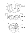
- the stroke-limiting collar (designated 10) is comprised of a pair of identical cam members 11a and 11b which mate together, as shown in Fig. 3.
- the cam member 11a has a generally cylindrical body 12, the upper portion (in the Fig. 2 view) of which has a pair of flanges or ramp members 14 and 16 which extend radially outwardly from the body 12 on either side.
- the ramp members 14 and 16 provide a pair of inclined axially and radially extending cam surfaces 18 and 20, respectively.
- the ramp members have arcuately extending guide slots 22 and 24 with inner edges which are spaced radially outwardly from outer peripheral surface 26 of the body 12 in order to provide clearance for attaching bolts 27 which are shown in Fig. 3.
- a U-shaped aperture or slot 28 for receiving the piston rod 30 of a hydraulic piston and cylinder unit extends into the central portion of the body 12.
- the slot 28 permits the cam members 11a and 11b of the collar 10 to be slid on and off the rod without disconnecting the rod from the apparatus to which it is connected.
- the size of the slot 28 can be varied to accommodate different rod sizes.
- the collar 10 is formed by sliding a pair of cam members 11a and 11b onto the rod 30, each with its ramp members 14 engaging the ramp member 16 of the other cam member.
- the cam members may be rotated with respect to each other similarly to a screwing action until the coupled pair has the desired thickness between the oppositely facing abutment surfaces 32 at the outer ends of the bodies 12. Then, the two cam members are bolted rigidly together by means such as bolts 27 or cap screws.
Landscapes
- Engineering & Computer Science (AREA)
- Physics & Mathematics (AREA)
- Fluid Mechanics (AREA)
- Mechanical Engineering (AREA)
- General Engineering & Computer Science (AREA)
- Mutual Connection Of Rods And Tubes (AREA)
- Pistons, Piston Rings, And Cylinders (AREA)
- Actuator (AREA)
- Pivots And Pivotal Connections (AREA)
Priority Applications (1)
| Application Number | Priority Date | Filing Date | Title |
|---|---|---|---|
| AT84105915T ATE27342T1 (de) | 1983-06-13 | 1984-05-24 | Hubbegrenzungsring fuer einen kolben und zylinder. |
Applications Claiming Priority (2)
| Application Number | Priority Date | Filing Date | Title |
|---|---|---|---|
| US06/504,004 US4469014A (en) | 1983-06-13 | 1983-06-13 | Cylinder spacer |
| US504004 | 1983-06-13 |
Publications (3)
| Publication Number | Publication Date |
|---|---|
| EP0129096A2 true EP0129096A2 (de) | 1984-12-27 |
| EP0129096A3 EP0129096A3 (en) | 1985-11-27 |
| EP0129096B1 EP0129096B1 (de) | 1987-05-20 |
Family
ID=24004464
Family Applications (1)
| Application Number | Title | Priority Date | Filing Date |
|---|---|---|---|
| EP84105915A Expired EP0129096B1 (de) | 1983-06-13 | 1984-05-24 | Hubbegrenzungsring für einen Kolben und Zylinder |
Country Status (13)
| Country | Link |
|---|---|
| US (1) | US4469014A (de) |
| EP (1) | EP0129096B1 (de) |
| JP (1) | JPS6011707A (de) |
| AR (1) | AR232032A1 (de) |
| AT (1) | ATE27342T1 (de) |
| AU (1) | AU546716B2 (de) |
| BR (1) | BR8402633A (de) |
| CA (1) | CA1206395A (de) |
| DE (1) | DE3463825D1 (de) |
| DK (1) | DK288284A (de) |
| ES (1) | ES289478Y (de) |
| IE (1) | IE55826B1 (de) |
| ZA (1) | ZA844422B (de) |
Families Citing this family (10)
| Publication number | Priority date | Publication date | Assignee | Title |
|---|---|---|---|---|
| US4747723A (en) * | 1987-02-06 | 1988-05-31 | Hasley George E | Universal joint coupling |
| US4821624A (en) * | 1988-02-29 | 1989-04-18 | Deere & Company | Stroke limiter for hydraulic cylinder |
| US5014598A (en) * | 1988-12-30 | 1991-05-14 | Neles-Jamesbury Corporation | Fluid pressure actuator |
| US5988293A (en) * | 1998-05-12 | 1999-11-23 | Deere & Company | Gauge structure for a cylinder operated depth control |
| RU2189505C1 (ru) * | 2001-08-29 | 2002-09-20 | Хмелевских Александр Иванович | Подложка |
| WO2006061673A1 (en) * | 2004-12-09 | 2006-06-15 | Infineon Technologies Ag | Semiconductor package having at least two semiconductor chips and method of assembling the semiconductor package |
| DE112012003874A5 (de) * | 2011-09-16 | 2014-06-05 | Schaeffler Technologies AG & Co. KG | Anschlaganordnung für die eingefahrene Kolbenstange eines Geberzylinders |
| US10543817B2 (en) * | 2016-12-15 | 2020-01-28 | Schwing America, Inc. | Powered rear outrigger systems |
| US10167888B2 (en) * | 2016-12-29 | 2019-01-01 | Shon E. Barker | Multi-orientable strut channel support system |
| JP7313193B2 (ja) * | 2019-05-29 | 2023-07-24 | 三菱重工エンジン&ターボチャージャ株式会社 | 軸継手装置および軸継手装置の回転位相調整方法 |
Family Cites Families (12)
| Publication number | Priority date | Publication date | Assignee | Title |
|---|---|---|---|---|
| US1496485A (en) * | 1922-07-25 | 1924-06-03 | Neal Newton Mccain | Picker cam |
| US1584310A (en) * | 1925-11-16 | 1926-05-11 | Draper Corp | Cam for looms |
| US2763481A (en) * | 1952-04-17 | 1956-09-18 | Harry H Hackett | Pneumatic feed attachment for tape dispensers |
| DE1247138B (de) * | 1963-03-12 | 1967-08-10 | Ingbuero Gebrueder Holtschmidt | Hydraulischer Antrieb mit einstellbarem Hub |
| DE2340555A1 (de) * | 1973-08-10 | 1975-02-27 | Schleicher Kg Hermann | Vorrichtung zum periodischen laengsbewegen von stangen- oder bandfoermigen werkstuecken |
| US3958493A (en) * | 1973-08-20 | 1976-05-25 | Tokico Ltd. | Multiple-stage actuating device |
| US3905279A (en) * | 1973-09-13 | 1975-09-16 | United Hydraulics Corp | Piston and cylinder assembly with external mechanical lock |
| US3921504A (en) * | 1973-09-27 | 1975-11-25 | Owens Illinois Inc | Adjustable stroke invert drive motor for a glass forming machine |
| US3858987A (en) * | 1974-05-21 | 1975-01-07 | Siemens Ag | Drive shaft flange coupling structure having a fixed shear speed |
| DE2651398A1 (de) * | 1976-11-11 | 1978-05-18 | Willi Horcher | Stell- oder betaetigungsorgan fuer ein hin und her zu bewegendes funktionselement |
| US4073345A (en) * | 1977-02-14 | 1978-02-14 | Miller Maurice E | Disc harrow wheel lock-down with depth control adjustment structure |
| US4155433A (en) * | 1977-10-04 | 1979-05-22 | P. L. Porter Company | Stroke-limiting stop for positioning device |
-
1983
- 1983-06-13 US US06/504,004 patent/US4469014A/en not_active Expired - Lifetime
-
1984
- 1984-05-16 CA CA000454470A patent/CA1206395A/en not_active Expired
- 1984-05-24 DE DE8484105915T patent/DE3463825D1/de not_active Expired
- 1984-05-24 EP EP84105915A patent/EP0129096B1/de not_active Expired
- 1984-05-24 AT AT84105915T patent/ATE27342T1/de not_active IP Right Cessation
- 1984-05-31 BR BR8402633A patent/BR8402633A/pt unknown
- 1984-06-04 AU AU28994/84A patent/AU546716B2/en not_active Ceased
- 1984-06-12 IE IE1470/84A patent/IE55826B1/xx unknown
- 1984-06-12 ES ES1984289478U patent/ES289478Y/es not_active Expired
- 1984-06-12 AR AR296899A patent/AR232032A1/es active
- 1984-06-12 ZA ZA844422A patent/ZA844422B/xx unknown
- 1984-06-12 DK DK288284A patent/DK288284A/da unknown
- 1984-06-13 JP JP59121661A patent/JPS6011707A/ja active Pending
Also Published As
| Publication number | Publication date |
|---|---|
| AU2899484A (en) | 1984-12-20 |
| EP0129096A3 (en) | 1985-11-27 |
| DK288284A (da) | 1984-12-14 |
| DK288284D0 (da) | 1984-06-12 |
| CA1206395A (en) | 1986-06-24 |
| JPS6011707A (ja) | 1985-01-22 |
| ES289478U (es) | 1986-02-16 |
| IE55826B1 (en) | 1991-01-30 |
| EP0129096B1 (de) | 1987-05-20 |
| BR8402633A (pt) | 1985-04-30 |
| ZA844422B (en) | 1986-01-29 |
| ATE27342T1 (de) | 1987-06-15 |
| AR232032A1 (es) | 1985-04-30 |
| ES289478Y (es) | 1986-10-01 |
| IE841470L (en) | 1984-12-13 |
| AU546716B2 (en) | 1985-09-12 |
| DE3463825D1 (en) | 1987-06-25 |
| US4469014A (en) | 1984-09-04 |
Similar Documents
| Publication | Publication Date | Title |
|---|---|---|
| EP0129096B1 (de) | Hubbegrenzungsring für einen Kolben und Zylinder | |
| US5674034A (en) | Locking nut assembly | |
| US3908499A (en) | Knife retainer | |
| US3844323A (en) | Split lock ring | |
| EP0125452B1 (de) | Anordnung zum Befestigen eines Walzenrings auf einer fliegend gelagerten Walzenwelle | |
| US4136989A (en) | Expandable annular cam-type locking device for a shaft | |
| US20180339377A1 (en) | Concentric Actuation and Reaction Torque Transfer System | |
| EP0394694B1 (de) | Hydraulische Einspannvorrichtung | |
| US4688731A (en) | Means for securing cutting or breaker elements to a rotatable member | |
| US4448455A (en) | Releasable auxiliary wheel coupling mechanism | |
| US4200407A (en) | Bolted annular locking collar for a shaft | |
| US2621590A (en) | Plate clamping mechanism for printing cylinders | |
| US4669338A (en) | Ratcheting box wrench | |
| US4570949A (en) | Chuck | |
| US20190178283A1 (en) | Concentric actuation and reaction torque transfer system | |
| CA2113264A1 (en) | Device for Shaping-Dough Portions | |
| US4744271A (en) | Ratcheting box wrench | |
| US4176738A (en) | Piston stroke adjusting arrangement for disc-type friction clutches and brakes | |
| US4676126A (en) | Adjustable wrench head for spanner nuts | |
| US4732083A (en) | Rotary die cylinder assembly | |
| US3724367A (en) | Print drum clamp | |
| US4906124A (en) | Multi-piece eccentric assembly | |
| DE2855702C2 (de) | Scheibenbremse für Fahrzeuge | |
| EP0191626A1 (de) | Selbstverstärkende Scheibenbremse | |
| US3043151A (en) | Variable pitch sheave |
Legal Events
| Date | Code | Title | Description |
|---|---|---|---|
| PUAI | Public reference made under article 153(3) epc to a published international application that has entered the european phase |
Free format text: ORIGINAL CODE: 0009012 |
|
| AK | Designated contracting states |
Designated state(s): AT BE CH DE FR GB IT LI NL SE |
|
| 17P | Request for examination filed |
Effective date: 19841220 |
|
| PUAL | Search report despatched |
Free format text: ORIGINAL CODE: 0009013 |
|
| AK | Designated contracting states |
Designated state(s): AT BE CH DE FR GB IT LI NL SE |
|
| RHK1 | Main classification (correction) |
Ipc: F15B 15/24 |
|
| 17Q | First examination report despatched |
Effective date: 19860801 |
|
| ITF | It: translation for a ep patent filed | ||
| GRAA | (expected) grant |
Free format text: ORIGINAL CODE: 0009210 |
|
| AK | Designated contracting states |
Kind code of ref document: B1 Designated state(s): AT BE CH DE FR GB IT LI NL SE |
|
| REF | Corresponds to: |
Ref document number: 27342 Country of ref document: AT Date of ref document: 19870615 Kind code of ref document: T |
|
| PGFP | Annual fee paid to national office [announced via postgrant information from national office to epo] |
Ref country code: NL Payment date: 19870531 Year of fee payment: 4 |
|
| REF | Corresponds to: |
Ref document number: 3463825 Country of ref document: DE Date of ref document: 19870625 |
|
| ET | Fr: translation filed | ||
| PLBE | No opposition filed within time limit |
Free format text: ORIGINAL CODE: 0009261 |
|
| STAA | Information on the status of an ep patent application or granted ep patent |
Free format text: STATUS: NO OPPOSITION FILED WITHIN TIME LIMIT |
|
| 26N | No opposition filed | ||
| PG25 | Lapsed in a contracting state [announced via postgrant information from national office to epo] |
Ref country code: AT Effective date: 19880524 |
|
| PG25 | Lapsed in a contracting state [announced via postgrant information from national office to epo] |
Ref country code: SE Effective date: 19880525 |
|
| PG25 | Lapsed in a contracting state [announced via postgrant information from national office to epo] |
Ref country code: LI Effective date: 19880531 Ref country code: CH Effective date: 19880531 |
|
| BERE | Be: lapsed |
Owner name: DEERE & CY Effective date: 19880531 |
|
| PG25 | Lapsed in a contracting state [announced via postgrant information from national office to epo] |
Ref country code: NL Effective date: 19881201 |
|
| NLV4 | Nl: lapsed or anulled due to non-payment of the annual fee | ||
| REG | Reference to a national code |
Ref country code: CH Ref legal event code: PL |
|
| PG25 | Lapsed in a contracting state [announced via postgrant information from national office to epo] |
Ref country code: BE Effective date: 19890531 |
|
| REG | Reference to a national code |
Ref country code: FR Ref legal event code: ST |
|
| REG | Reference to a national code |
Ref country code: FR Ref legal event code: RC |
|
| REG | Reference to a national code |
Ref country code: FR Ref legal event code: DA |
|
| PGFP | Annual fee paid to national office [announced via postgrant information from national office to epo] |
Ref country code: GB Payment date: 19920416 Year of fee payment: 9 |
|
| PGFP | Annual fee paid to national office [announced via postgrant information from national office to epo] |
Ref country code: FR Payment date: 19920513 Year of fee payment: 9 |
|
| ITTA | It: last paid annual fee | ||
| PGFP | Annual fee paid to national office [announced via postgrant information from national office to epo] |
Ref country code: DE Payment date: 19920706 Year of fee payment: 9 |
|
| PG25 | Lapsed in a contracting state [announced via postgrant information from national office to epo] |
Ref country code: GB Effective date: 19930524 |
|
| GBPC | Gb: european patent ceased through non-payment of renewal fee |
Effective date: 19930524 |
|
| PG25 | Lapsed in a contracting state [announced via postgrant information from national office to epo] |
Ref country code: FR Effective date: 19940131 |
|
| PG25 | Lapsed in a contracting state [announced via postgrant information from national office to epo] |
Ref country code: DE Effective date: 19940201 |
|
| REG | Reference to a national code |
Ref country code: FR Ref legal event code: ST |
|
| EUG | Se: european patent has lapsed |
Ref document number: 84105915.7 Effective date: 19890518 |