EP0129101B1 - Dispositif combiné d'échange de chaleur et d'aération - Google Patents
Dispositif combiné d'échange de chaleur et d'aération Download PDFInfo
- Publication number
- EP0129101B1 EP0129101B1 EP84105994A EP84105994A EP0129101B1 EP 0129101 B1 EP0129101 B1 EP 0129101B1 EP 84105994 A EP84105994 A EP 84105994A EP 84105994 A EP84105994 A EP 84105994A EP 0129101 B1 EP0129101 B1 EP 0129101B1
- Authority
- EP
- European Patent Office
- Prior art keywords
- conduit
- exhaust air
- plate
- heat exchanger
- air
- Prior art date
- Legal status (The legal status is an assumption and is not a legal conclusion. Google has not performed a legal analysis and makes no representation as to the accuracy of the status listed.)
- Expired - Lifetime
Links
- 238000009423 ventilation Methods 0.000 title description 7
- 239000011888 foil Substances 0.000 claims abstract 3
- 238000010438 heat treatment Methods 0.000 claims abstract 2
- 230000000087 stabilizing effect Effects 0.000 claims abstract 2
- 239000000428 dust Substances 0.000 claims description 20
- 238000004140 cleaning Methods 0.000 claims description 7
- 239000000463 material Substances 0.000 claims description 6
- 230000000694 effects Effects 0.000 claims description 4
- 239000002245 particle Substances 0.000 claims description 3
- 230000001154 acute effect Effects 0.000 claims description 2
- 238000011144 upstream manufacturing Methods 0.000 claims description 2
- 230000001174 ascending effect Effects 0.000 claims 1
- 230000001681 protective effect Effects 0.000 description 8
- 238000009434 installation Methods 0.000 description 2
- 238000009825 accumulation Methods 0.000 description 1
- 239000000356 contaminant Substances 0.000 description 1
- 230000001419 dependent effect Effects 0.000 description 1
- 230000009931 harmful effect Effects 0.000 description 1
- 230000000630 rising effect Effects 0.000 description 1
- XLYOFNOQVPJJNP-UHFFFAOYSA-N water Substances O XLYOFNOQVPJJNP-UHFFFAOYSA-N 0.000 description 1
Images

Classifications
-
- A—HUMAN NECESSITIES
- A01—AGRICULTURE; FORESTRY; ANIMAL HUSBANDRY; HUNTING; TRAPPING; FISHING
- A01K—ANIMAL HUSBANDRY; AVICULTURE; APICULTURE; PISCICULTURE; FISHING; REARING OR BREEDING ANIMALS, NOT OTHERWISE PROVIDED FOR; NEW BREEDS OF ANIMALS
- A01K1/00—Housing animals; Equipment therefor
- A01K1/0047—Air-conditioning, e.g. ventilation, of animal housings
- A01K1/0076—Arrangement of heaters or heat exchangers
Definitions
- the invention relates to a countercurrent heat exchange and ventilation device with the features of the preamble of claim 1.
- Such a device is known from DE-OS 29 39 827, in which the exhaust duct is a continuous central tube from below the barn floor to over the roof, which is enclosed in the upper region at the height of the roof row by an outer cylinder that the Heat exchanger takes up.
- the heat exchanger is limited in the radial direction by an inner cylinder and an outer cylinder.
- the inner baffle and the outer baffle have window-like recesses, the recesses contained in the inner baffle extending over the entire height of the heat exchanger, while the recesses provided in the outer baffle extend only over part of the height of the outer baffle.
- the wall of the exhaust duct thus represents the inner boundary of the concentric heat exchanger.
- the two swiveling shut-off plates arranged one above the other serve exclusively to shut off the inner cylinder.
- the exhaust air sucked in via the floor of the barn initially flows upwards through the inner cylinder and the upper area is blocked - through the concentric heat exchanger and then back into the inner cylinder and out into the open air.
- the fan is fixed in the inner cylinder and cannot be switched.
- the heat exchanger is arranged in a sleeve-like manner around the exhaust duct, which requires considerable intervention in the building during installation and also requires structural changes during removal.
- the object of the invention is to develop such a heat exchanger and ventilation device in such a way that with the simplest possible means and the least possible design outlay without constructional changes in the existing exhaust duct, a prefabricated device can be created which ensures perfect summer and winter operation.
- a combined heat exchange and ventilation device which ensures perfect winter and summer operation, is achieved with extremely little effort and in a particularly simple and expedient manner. It is only necessary to divide the frame or shaft device, which receives the heat exchanger, into two through channels or shaft sections, one of which is filled by the heat exchanger and the other of which remains free, i.e. Allows an unhindered passage of air, as well as a shut-off device in the form of a shut-off plate attached to a shaft wall and a fan which is movably attached to the shut-off plate or is arranged in the exhaust air duct independently of the shut-off plate.
- the part of the exhaust duct that connects the heat exchanger e.g. contains a honeycomb exchanger, locked, while the other part is put into operation by opening the shut-off plate, so that the exhaust air fan no longer conveys the exhaust air through the heat exchanger to the shaft section, but directly to the outside through the shaft section formed next to it.
- the extent of ventilation can be varied as required by continuously adjusting the plate, the plate being operated manually or by an operator by an operator, or the opening and closing of the plate depending on the temperature can be controlled automatically.
- a dust trap is achieved if the shape of the plate and the design of the shaft walls, which simultaneously support the heat exchanger, are selected accordingly.
- the heavy dust particles with a small amount of air are deflected by the air flow entering the heat exchanger, sweep along the underside of the closed plate, then step into the recesses provided for this purpose in the closed exhaust duct and collect on the top the plate so that they can be removed from there to a separate dust chamber for dust removal. This can significantly reduce the dust load on the heat exchanger.
- the heat exchanger according to the invention is preferably made of a thin material or a strong film which is set into vibration by the air flowing through the heat exchanger in order to support the cleaning effect of the walls of the heat exchanger.
- This cleaning effect is a self-cleaning effect which results from the vertical arrangement of the heat exchanger channels according to the invention, the dust accumulated in the channels loosening itself and sinking downwards.
- the inner walls of the individual channels of the heat exchanger are preferably designed such that they have air guide grooves or channels running at an acute angle to the axial direction, so that the channels in each one Channel of the heat exchanger existing air column receives a twist and the air column loosens at the corners of the channels.
- the air guide grooves or channels are preferably sawtooth-shaped in cross-section, the rising part of the sawtooth lying downstream and the falling part of the sawtooth lying upstream.
- the heat exchanger in a further embodiment of the invention, it is proposed to design the heat exchanger as a deep-drawn integral housing, which is arranged as a whole on the stable ceiling or in the chimney, the two fans being integrated in this deep-drawn housing and all the precautions (brackets required for the later use of the fans) , Connections) are provided, a cleaning cover for dust removal is provided, etc.
- the invention proposes to protect the upper end of the throughflow channels of the honeycomb exchanger against hail, sunlight and the like.
- a honeycomb exchanger-spanning protective plate is placed on the upper end of the heat exchanger or on the chimney, the recesses for the has open channels at the top.
- the protective plate is preferably designed so that it e.g. consists of PVC and has slots at a distance from the flow channels.
- the webs between the slots are curved in a special way so that they overlap the upper end of the closed channels.
- the bulges with an approximately U-shaped cross section are e.g. shaped so that the material with the greatest curvature is much thicker (e.g. 4 mm) than at the tapered ends (e.g. 1 mm).
- the heat exchanger with vertical throughflow channels preferably has a vertical frame or shaft on its outer circumference, which is created by stacking individual ring elements one above the other, into which the heat exchanger is then inserted and fastened.
- the individual elements consist, for example, of plastic rings, which are stacked on top of one another like concrete rings for well shafts and thus form the shaft for the heat exchanger. In this way, a transportable, shaft-type heat exchange device that can be attached or connected to the barn building is achieved, which can be used in a simple manner and just as easily removed and, if necessary, reused elsewhere.
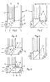
- a horizontal exhaust duct 1 is connected to a vertical exhaust duct 2, which is composed of individual annular sections which are stacked one above the other.
- a fan 3 is provided at the outlet of the exhaust air duct 1.
- the exhaust duct 2 has a wall 4 which divides the duct 2 into two duct sections A and B.
- the honeycomb heat exchanger 5 is provided, which is fastened to the boundary walls, while the shaft section B is free and allows unimpeded air passage if the shut-off device 6 is closed in the form of a shut-off plate, which is articulated at 7 on the shaft 2 .
- an exhaust air fan B is fastened to the plate 6 and can be pivoted together with the flap 6.
- Fig. 2 The open position of the flap 6 is shown in Fig. 2.
- Fig. 1 that is, with the plate 6 closed, the exhaust air 9 is guided through the action of the fans 3 and 8 through the heat exchanger 5; this represents the heat exchanger operation, i.e. represents the winter operation.
- FIG. 2 the entire exhaust air is discharged in the direction of the arrows 10 by the fan B through the exhaust duct section 8. This represents summer operation, in which no exhaust air is led through the heat exchanger, but the heat exchanger is ineffective.
- FIGS. 3 and 4 which corresponds in principle to that according to FIGS. 1 and 2, instead of the fan 8 fastened to the plate 6, a plate 11 is provided, which is mounted on the wall 4 at 12, and this plate 11 is assigned a stationary fan 13 which is inserted obliquely into the exhaust air duct 1 and which, when the plate is closed, guides the exhaust air 9 through the heat exchanger 5, while (FIG. 4) with the plate 11 open, the exhaust air 10 in summer operation through the shaft section 8 is promoted above.
- FIGS. 3 and 4 the embodiment according to FIGS. 3 and 4 has been further developed in such a way that a dust trap is provided on the shut-off plate 11.
- This dust trap is in the case of the embodiment 5 designed so that on the wall 4 in the region of the hinge 12 of the plate 11, an air duct 14, 15 is provided on the wall 4, which deflects the exhaust air flow guided on the underside of the plate 11, which contains the essential dust particles and deposited on the top of the plate 11, as shown at 16, from where the dust can be discharged into a dust chamber.
- the dust trap is achieved in that the plate 11 in the case of FIG. 3 is provided with slots which run perpendicular to the plane of the drawing, so that dust can be separated through these slots.
- the heat exchange and ventilation device according to the invention is arranged in a special embodiment of the invention, which is shown in FIG. 6, in a housing 17, which is a one-piece deep-drawing component.
- This housing 17 with the parts of the heat exchange and ventilation device accommodated therein is fixed on the stable ceiling D or in the exhaust duct 2 or chimney. It consists of a section 19 for receiving the fan 3, and a central section 20.
- the section 18 is separated from the section 20 by a plate 21.
- the plate 21 is articulated at 22. In its closed position (shown), it cooperates with a stiffening between the housing sections 18 and 20 so that the duct carrying the exhaust air 10 is separated from the rest of the part.
- a detachable cover 24 is provided, which rests on lugs 25 and 26.
- This lid is a cleaning lid for removing dust and dirt.
- a stowage nose which passes over a deformation 28 into the central section 20, at the lower end of which a water drain is provided at 29.
- This deformation 28 is assigned a corresponding counter-deformation 30 at the lower limit of the heat exchanger 5, which represents a locking of the heat exchanger in the housing.
- FIGS. 7 and 8 diagrammatically show 31 an individual air duct of the honeycomb exchanger 5.
- This channel is preferably square, but can also be triangular or in another cross-sectional shape.
- inclined grooves or channels 32 are provided, which preferably extend uniformly over the entire inner surfaces of the channels.
- These channels are sawtooth-shaped deformations 33 are formed, the end wall 34 of the sawtooth facing the air flow 35.
- the material from which the individual channels of the honeycomb exchanger are made is a relatively thin material, e.g. in the form of a thick film. Since this material, which is made of plastic, is affected by external influences, e.g. can be considerably damaged by hail, sunlight, etc., it has proven to be expedient to provide the honeycomb exchanger on the top of the fireplace with a protective plate 36 which is rust-like, such that the webs 37 of such a plate have the outer ends overlap the closed channels 38 of the honeycomb exchanger so that harmful effects can be kept away from the heat exchanger itself.
Landscapes
- Life Sciences & Earth Sciences (AREA)
- Environmental Sciences (AREA)
- Zoology (AREA)
- Animal Husbandry (AREA)
- Biodiversity & Conservation Biology (AREA)
- Heat-Exchange Devices With Radiators And Conduit Assemblies (AREA)
- Central Air Conditioning (AREA)
- Ventilation (AREA)
- Greenhouses (AREA)
- Catching Or Destruction (AREA)
- Other Air-Conditioning Systems (AREA)
- Building Environments (AREA)
Claims (11)
Priority Applications (1)
| Application Number | Priority Date | Filing Date | Title |
|---|---|---|---|
| AT84105994T ATE51493T1 (de) | 1983-06-18 | 1984-05-25 | Kombinierte waermetausch- und lueftungsvorrichtung. |
Applications Claiming Priority (2)
| Application Number | Priority Date | Filing Date | Title |
|---|---|---|---|
| DE19838317777U DE8317777U1 (de) | 1983-06-18 | 1983-06-18 | Kombinierte waermetausch- und lueftungsvorrichtung |
| DE8317777U | 1983-06-18 |
Publications (3)
| Publication Number | Publication Date |
|---|---|
| EP0129101A2 EP0129101A2 (fr) | 1984-12-27 |
| EP0129101A3 EP0129101A3 (en) | 1986-10-22 |
| EP0129101B1 true EP0129101B1 (fr) | 1990-04-04 |
Family
ID=6754378
Family Applications (1)
| Application Number | Title | Priority Date | Filing Date |
|---|---|---|---|
| EP84105994A Expired - Lifetime EP0129101B1 (fr) | 1983-06-18 | 1984-05-25 | Dispositif combiné d'échange de chaleur et d'aération |
Country Status (3)
| Country | Link |
|---|---|
| EP (1) | EP0129101B1 (fr) |
| AT (1) | ATE51493T1 (fr) |
| DE (2) | DE8317777U1 (fr) |
Families Citing this family (3)
| Publication number | Priority date | Publication date | Assignee | Title |
|---|---|---|---|---|
| DE8715600U1 (de) * | 1987-11-25 | 1988-07-07 | Schönhammer, Johann, 8317 Mengkofen | Untere Abschlußwand einer Wanne, die den unteren Abschluß eines Ab- und Zuluftschachts bildet |
| NL2004108C2 (nl) * | 2010-01-18 | 2011-07-19 | Ven Beheer B V Van De | Verwarmingsinrichting voor het verwarmen van lucht. |
| DE202010002960U1 (de) * | 2010-02-26 | 2011-08-01 | Big Dutchman International Gmbh | Zuluftkamin für Nutztierställe |
Citations (1)
| Publication number | Priority date | Publication date | Assignee | Title |
|---|---|---|---|---|
| EP0106259A2 (fr) * | 1982-10-07 | 1984-04-25 | Heinrich Drexl Kommanditgesellschaft | Dispositif de récupération de la chaleur pour un bâtiment |
Family Cites Families (7)
| Publication number | Priority date | Publication date | Assignee | Title |
|---|---|---|---|---|
| GB1426716A (en) * | 1972-03-10 | 1976-03-03 | Conex Sanbra Ltd | Convector space heating or cooling apparatus |
| DE2513505A1 (de) * | 1975-03-26 | 1976-10-14 | Thermal Waerme Kaelte Klima | Waermerueckgewinnungsgeraet |
| DE2842974A1 (de) * | 1978-10-02 | 1980-04-10 | Hermann Dieterichs | Vorrichtung fuer die klimatisierung von raeumen mit entsprechendem luftwechsel, insbesondere bei gefluegel-maststaellen |
| US4336748A (en) * | 1979-09-30 | 1982-06-29 | Axis Products Limited | Fluid exchanger |
| DE2939827A1 (de) * | 1979-10-01 | 1981-04-23 | Metallbau Sevelen AG, Sevelen, St. Gallen | Waermetauscher, insbesondee zur verwertung von abluftwaerme |
| DE3017166A1 (de) * | 1980-05-05 | 1981-11-12 | Ökotherm Vertriebs-Gesellschaft mbH, 2351 Hagen | Vorrichtung zum saeubern von stalluft |
| DE3139772A1 (de) * | 1981-10-07 | 1983-04-21 | Gebrüder Schmeing, 4280 Borken | "verfahren und vorrichtung zur belueftung von innenraeumen, vorzugsweise staellen" |
-
1983
- 1983-06-18 DE DE19838317777U patent/DE8317777U1/de not_active Expired
-
1984
- 1984-05-25 EP EP84105994A patent/EP0129101B1/fr not_active Expired - Lifetime
- 1984-05-25 AT AT84105994T patent/ATE51493T1/de active
- 1984-05-25 DE DE8484105994T patent/DE3481804D1/de not_active Expired - Lifetime
Patent Citations (1)
| Publication number | Priority date | Publication date | Assignee | Title |
|---|---|---|---|---|
| EP0106259A2 (fr) * | 1982-10-07 | 1984-04-25 | Heinrich Drexl Kommanditgesellschaft | Dispositif de récupération de la chaleur pour un bâtiment |
Also Published As
| Publication number | Publication date |
|---|---|
| EP0129101A3 (en) | 1986-10-22 |
| EP0129101A2 (fr) | 1984-12-27 |
| ATE51493T1 (de) | 1990-04-15 |
| DE3481804D1 (de) | 1990-05-10 |
| DE8317777U1 (de) | 1984-01-12 |
Similar Documents
| Publication | Publication Date | Title |
|---|---|---|
| EP2594725B1 (fr) | Fenêtre | |
| EP0114241A2 (fr) | Dispositif de ventilation | |
| DE102007023664A1 (de) | Plattenaufteilanlage | |
| EP0129101B1 (fr) | Dispositif combiné d'échange de chaleur et d'aération | |
| DE3040739C2 (fr) | ||
| DE2256675A1 (de) | Entlueftungsfirstkappe | |
| DE2720569A1 (de) | Vorrichtung zur be- und entlueftung von raeumen und/oder zur durchfuehrung der lufterneuerung bei prozesstechnischen anlagen | |
| EP1488175B1 (fr) | Systeme de renouvellement d'air comprenant un echangeur thermique, concu pour aerer une piece d'un batiment | |
| EP0125673B1 (fr) | Echangeur de chaleur | |
| DE2408212A1 (de) | Be- und entlueftungsvorrichtung fuer gebaeuderaeume | |
| DE1679539A1 (de) | Verteilkanal fuer uebersaettigte Luft von einer Lueftungs- und Klimaanlage | |
| DE1962090A1 (de) | Belueftungseinrichtung | |
| EP0607791B1 (fr) | Aérateur de toit | |
| DE19604504A1 (de) | Bodenauslaß | |
| DE2226974A1 (de) | Ventilator | |
| EP2698497A2 (fr) | Doublure intérieure pour fenêtre et agencement de fenêtre doté d'une fenêtre | |
| DE1220104B (de) | Lueftungseinrichtung fuer Ziegeldaecher od. dgl. | |
| DE2403697C2 (de) | Dachentlüfter | |
| DE2625575A1 (de) | Entlueftungsvorrichtung fuer gebaeude | |
| DE1257804B (de) | Luftbeaufschlagte Kondensationsanlage | |
| DE2140369B2 (de) | Lüftungsgitter für Fahrzeuge, insbesondere Schienentriebfahrzeuge | |
| DE3246341A1 (de) | Vorrichtung zum waschen von gasen, vornehmlich zum reinigen, befeuchten und kuehlen von luft | |
| DE7524852U (de) | Fettfangfilter | |
| DE3841513A1 (de) | Verfahren zum entstauben eines katalysators | |
| DE1756082A1 (de) | Schwingmaschine mit Kuehlung zum Foerdern oder Sieben von heissem Schuettgut |
Legal Events
| Date | Code | Title | Description |
|---|---|---|---|
| PUAI | Public reference made under article 153(3) epc to a published international application that has entered the european phase |
Free format text: ORIGINAL CODE: 0009012 |
|
| AK | Designated contracting states |
Designated state(s): AT BE CH DE FR GB IT LI LU NL SE |
|
| PUAL | Search report despatched |
Free format text: ORIGINAL CODE: 0009013 |
|
| AK | Designated contracting states |
Kind code of ref document: A3 Designated state(s): AT BE CH DE FR GB IT LI LU NL SE |
|
| 17P | Request for examination filed |
Effective date: 19870416 |
|
| 17Q | First examination report despatched |
Effective date: 19880530 |
|
| RAP1 | Party data changed (applicant data changed or rights of an application transferred) |
Owner name: SCHOENHAMMER, JOHANN Owner name: PENZKOFER, LUDWIG |
|
| GRAA | (expected) grant |
Free format text: ORIGINAL CODE: 0009210 |
|
| AK | Designated contracting states |
Kind code of ref document: B1 Designated state(s): AT BE CH DE FR GB IT LI LU NL SE |
|
| PG25 | Lapsed in a contracting state [announced via postgrant information from national office to epo] |
Ref country code: SE Effective date: 19900404 Ref country code: NL Effective date: 19900404 Ref country code: IT Free format text: LAPSE BECAUSE OF FAILURE TO SUBMIT A TRANSLATION OF THE DESCRIPTION OR TO PAY THE FEE WITHIN THE PRESCRIBED TIME-LIMIT;WARNING: LAPSES OF ITALIAN PATENTS WITH EFFECTIVE DATE BEFORE 2007 MAY HAVE OCCURRED AT ANY TIME BEFORE 2007. THE CORRECT EFFECTIVE DATE MAY BE DIFFERENT FROM THE ONE RECORDED. Effective date: 19900404 Ref country code: GB Effective date: 19900404 Ref country code: FR Effective date: 19900404 Ref country code: BE Effective date: 19900404 |
|
| REF | Corresponds to: |
Ref document number: 51493 Country of ref document: AT Date of ref document: 19900415 Kind code of ref document: T |
|
| REF | Corresponds to: |
Ref document number: 3481804 Country of ref document: DE Date of ref document: 19900510 |
|
| PG25 | Lapsed in a contracting state [announced via postgrant information from national office to epo] |
Ref country code: LU Free format text: LAPSE BECAUSE OF NON-PAYMENT OF DUE FEES Effective date: 19900531 |
|
| EN | Fr: translation not filed | ||
| NLV1 | Nl: lapsed or annulled due to failure to fulfill the requirements of art. 29p and 29m of the patents act | ||
| GBV | Gb: ep patent (uk) treated as always having been void in accordance with gb section 77(7)/1977 [no translation filed] | ||
| PLBE | No opposition filed within time limit |
Free format text: ORIGINAL CODE: 0009261 |
|
| STAA | Information on the status of an ep patent application or granted ep patent |
Free format text: STATUS: NO OPPOSITION FILED WITHIN TIME LIMIT |
|
| 26N | No opposition filed | ||
| PGFP | Annual fee paid to national office [announced via postgrant information from national office to epo] |
Ref country code: CH Payment date: 19920525 Year of fee payment: 9 |
|
| PGFP | Annual fee paid to national office [announced via postgrant information from national office to epo] |
Ref country code: AT Payment date: 19930528 Year of fee payment: 10 |
|
| PG25 | Lapsed in a contracting state [announced via postgrant information from national office to epo] |
Ref country code: LI Effective date: 19930531 Ref country code: CH Effective date: 19930531 |
|
| REG | Reference to a national code |
Ref country code: CH Ref legal event code: PL |
|
| PG25 | Lapsed in a contracting state [announced via postgrant information from national office to epo] |
Ref country code: AT Effective date: 19940525 |
|
| PGFP | Annual fee paid to national office [announced via postgrant information from national office to epo] |
Ref country code: DE Payment date: 20030726 Year of fee payment: 20 |