EP0129113B1 - Probensammeleinrichtung für in der Umgebungsluft enthaltene gasförmige radioaktive Stoffe - Google Patents
Probensammeleinrichtung für in der Umgebungsluft enthaltene gasförmige radioaktive Stoffe Download PDFInfo
- Publication number
- EP0129113B1 EP0129113B1 EP84106100A EP84106100A EP0129113B1 EP 0129113 B1 EP0129113 B1 EP 0129113B1 EP 84106100 A EP84106100 A EP 84106100A EP 84106100 A EP84106100 A EP 84106100A EP 0129113 B1 EP0129113 B1 EP 0129113B1
- Authority
- EP
- European Patent Office
- Prior art keywords
- gas
- bottle
- collecting
- measuring
- branches
- Prior art date
- Legal status (The legal status is an assumption and is not a legal conclusion. Google has not performed a legal analysis and makes no representation as to the accuracy of the status listed.)
- Expired
Links
- 238000005070 sampling Methods 0.000 title claims description 8
- 230000002285 radioactive effect Effects 0.000 title claims description 7
- HEMHJVSKTPXQMS-UHFFFAOYSA-M Sodium hydroxide Chemical compound [OH-].[Na+] HEMHJVSKTPXQMS-UHFFFAOYSA-M 0.000 claims description 56
- 238000010521 absorption reaction Methods 0.000 claims description 27
- 235000011121 sodium hydroxide Nutrition 0.000 claims description 19
- 239000007788 liquid Substances 0.000 claims description 10
- 238000007789 sealing Methods 0.000 claims description 5
- 239000004809 Teflon Substances 0.000 claims description 3
- 229920006362 Teflon® Polymers 0.000 claims description 3
- OKTJSMMVPCPJKN-UHFFFAOYSA-N Carbon Chemical compound [C] OKTJSMMVPCPJKN-UHFFFAOYSA-N 0.000 claims description 2
- 230000003321 amplification Effects 0.000 claims description 2
- 229910052799 carbon Inorganic materials 0.000 claims description 2
- 238000003199 nucleic acid amplification method Methods 0.000 claims description 2
- 230000001105 regulatory effect Effects 0.000 claims description 2
- 238000004458 analytical method Methods 0.000 claims 3
- 238000009434 installation Methods 0.000 claims 1
- 238000012544 monitoring process Methods 0.000 description 11
- 238000011144 upstream manufacturing Methods 0.000 description 8
- 238000005259 measurement Methods 0.000 description 7
- CURLTUGMZLYLDI-UHFFFAOYSA-N Carbon dioxide Chemical compound O=C=O CURLTUGMZLYLDI-UHFFFAOYSA-N 0.000 description 5
- 238000011156 evaluation Methods 0.000 description 5
- 238000004804 winding Methods 0.000 description 5
- 230000008878 coupling Effects 0.000 description 4
- 238000010168 coupling process Methods 0.000 description 4
- 238000005859 coupling reaction Methods 0.000 description 4
- 238000010586 diagram Methods 0.000 description 4
- 238000000034 method Methods 0.000 description 4
- 239000006096 absorbing agent Substances 0.000 description 3
- 239000003518 caustics Substances 0.000 description 3
- 238000013461 design Methods 0.000 description 3
- 238000010438 heat treatment Methods 0.000 description 3
- 238000000926 separation method Methods 0.000 description 3
- XLYOFNOQVPJJNP-UHFFFAOYSA-N water Substances O XLYOFNOQVPJJNP-UHFFFAOYSA-N 0.000 description 3
- 230000002745 absorbent Effects 0.000 description 2
- 239000002250 absorbent Substances 0.000 description 2
- 239000003513 alkali Substances 0.000 description 2
- 239000002585 base Substances 0.000 description 2
- 229910002092 carbon dioxide Inorganic materials 0.000 description 2
- 239000001569 carbon dioxide Substances 0.000 description 2
- 239000011521 glass Substances 0.000 description 2
- 230000008569 process Effects 0.000 description 2
- 230000000717 retained effect Effects 0.000 description 2
- 239000000725 suspension Substances 0.000 description 2
- 238000009423 ventilation Methods 0.000 description 2
- 230000002159 abnormal effect Effects 0.000 description 1
- 239000002253 acid Substances 0.000 description 1
- 230000033228 biological regulation Effects 0.000 description 1
- 229910002090 carbon oxide Inorganic materials 0.000 description 1
- 230000008859 change Effects 0.000 description 1
- 230000002950 deficient Effects 0.000 description 1
- 238000001514 detection method Methods 0.000 description 1
- 238000011161 development Methods 0.000 description 1
- 230000018109 developmental process Effects 0.000 description 1
- 238000005516 engineering process Methods 0.000 description 1
- 239000012530 fluid Substances 0.000 description 1
- 238000007654 immersion Methods 0.000 description 1
- 238000012423 maintenance Methods 0.000 description 1
- 230000014759 maintenance of location Effects 0.000 description 1
- 230000007257 malfunction Effects 0.000 description 1
- 239000002245 particle Substances 0.000 description 1
- 239000004033 plastic Substances 0.000 description 1
- 238000001556 precipitation Methods 0.000 description 1
- 238000002360 preparation method Methods 0.000 description 1
- 238000012545 processing Methods 0.000 description 1
- 238000000746 purification Methods 0.000 description 1
- 239000000941 radioactive substance Substances 0.000 description 1
- 238000011084 recovery Methods 0.000 description 1
- 230000009467 reduction Effects 0.000 description 1
- 238000012958 reprocessing Methods 0.000 description 1
- 230000000630 rising effect Effects 0.000 description 1
- 239000007787 solid Substances 0.000 description 1
- 229910001220 stainless steel Inorganic materials 0.000 description 1
- 239000010935 stainless steel Substances 0.000 description 1
Images

Classifications
-
- G—PHYSICS
- G01—MEASURING; TESTING
- G01N—INVESTIGATING OR ANALYSING MATERIALS BY DETERMINING THEIR CHEMICAL OR PHYSICAL PROPERTIES
- G01N1/00—Sampling; Preparing specimens for investigation
- G01N1/02—Devices for withdrawing samples
- G01N1/22—Devices for withdrawing samples in the gaseous state
- G01N1/24—Suction devices
-
- G—PHYSICS
- G21—NUCLEAR PHYSICS; NUCLEAR ENGINEERING
- G21C—NUCLEAR REACTORS
- G21C19/00—Arrangements for treating, for handling, or for facilitating the handling of, fuel or other materials which are used within the reactor, e.g. within its pressure vessel
- G21C19/28—Arrangements for introducing fluent material into the reactor core; Arrangements for removing fluent material from the reactor core
- G21C19/30—Arrangements for introducing fluent material into the reactor core; Arrangements for removing fluent material from the reactor core with continuous purification of circulating fluent material, e.g. by extraction of fission products deterioration or corrosion products, impurities, e.g. by cold traps
- G21C19/303—Arrangements for introducing fluent material into the reactor core; Arrangements for removing fluent material from the reactor core with continuous purification of circulating fluent material, e.g. by extraction of fission products deterioration or corrosion products, impurities, e.g. by cold traps specially adapted for gases
-
- Y—GENERAL TAGGING OF NEW TECHNOLOGICAL DEVELOPMENTS; GENERAL TAGGING OF CROSS-SECTIONAL TECHNOLOGIES SPANNING OVER SEVERAL SECTIONS OF THE IPC; TECHNICAL SUBJECTS COVERED BY FORMER USPC CROSS-REFERENCE ART COLLECTIONS [XRACs] AND DIGESTS
- Y02—TECHNOLOGIES OR APPLICATIONS FOR MITIGATION OR ADAPTATION AGAINST CLIMATE CHANGE
- Y02E—REDUCTION OF GREENHOUSE GAS [GHG] EMISSIONS, RELATED TO ENERGY GENERATION, TRANSMISSION OR DISTRIBUTION
- Y02E30/00—Energy generation of nuclear origin
- Y02E30/30—Nuclear fission reactors
Definitions
- the invention relates to a sample collection device for collecting the radioactive carbon isotope 14 C, which is contained in the form of C0 2 in the exhaust air of a nuclear power plant or other nuclear plant, according to the preamble of claim 1.
- a suitable absorption method is to be selected, which ensures that the amounts of radioactive carbon dioxide collected in the absorbent, collected in a collecting vessel, can be conveniently removed from the sample collection device and transported to a laboratory, where they can be easily and qualitatively chemically analyzed chemically should be able to draw conclusions about the amount of radioactive 14 C contained in the exhaust air.
- Monitoring during the quarterly surveillance period should be continuous; in addition, only relatively small volume flows need to be passed through the collecting vessel, because it is not about exhaust gas purification, but only about sampling in order to record the proportion of radioactive 14 C in the exhaust air. It is particularly important that during the monitoring period the sample collection device can be operated as automatically as possible without manual operations, which means that it must work intrinsically safe so that in the event of a fault (e.g.
- FIGS. 2, 4 and 5 of the aforementioned GB-A show exemplary embodiments in which each C0 2 separating branch consists of two collecting branches which are connected in parallel and can be switched on and off, each with a collecting vessel, with upstream and downstream switching valves arranged upstream and downstream of the collecting vessels , by means of which a separation of the respective CO Z -enriched collecting vessel and the switching on of a fresh, receptive collecting vessel is made possible.
- the sample gas that has been removed from water or C0 2 is returned to the exhaust air stack.
- the branching point lies behind the collecting branches, ie the entire gas stream sucked in by the exhaust gas chimney through the filter and pump is fed as a measuring gas stream to the collecting branches, which are each provided with mass flow meters. Since a single sample gas pump is common to all collecting branches, this means that if it fails, sampling must also be interrupted. However, since 14 C monitoring requires a continuous period of 3 months to be measured and evaluated, the known sample collection device is not suitable for this purpose. It should also be noted that flow meters, which cannot be operated with a precise or precisely adjustable pre-pressure, leave something to be desired with regard to the measuring accuracy.
- the set of tasks is solved in a sample collection device according to the preamble of claim 1 by the features specified in the characterizing part of claim 1.
- Advantageous further developments are in subclaims 2 to 10 specified.
- the pneumatic input of the sample collecting means shown in FIG. 1 and designated as a whole with PSE is via the intake line 1 0 and an upstream fine filter FO is connected to the exhaust duct of a nuclear power station or generally a nuclear facility (laboratory, reprocessing plant).
- the intake line 1 0 branches into the two intake branches i 11 , i 12 , each of which contains a series connection of gas pump P1 or P2 and a shut-off valve V1 or V2.
- One of the two suction branches, e.g. B. 1 11 is in operation, the other serves as a reserve branch and is automatically switched on in the event of a malfunction and shutdown of the intake branch in operation, so that the fault in the sick intake branch is eliminated, e.g. B.
- the gas pumps P1, P2 are preferably diaphragm compressor vacuum pumps, of a type in which the pump housing consists of high-quality, chemically resistant plastic parts.
- the diaphragm is driven by a shaded-pole motor using an eccentric.
- the pump is free of shaft seals, making it completely gas-tight. Thanks to the use of special bearings, it runs very quietly. In particular, it is very quiet, has small dimensions and is suitable for continuous operation.
- two parallel suction branches ensure sufficient redundancy for continuous operation; in special cases, more than two parallel suction branches 1 1 could also be provided if the sampling periods last longer than three months and / or if a suction branch fails to be repaired immediately.
- the intake branch 1 11 is in operation.
- a gas flow g o of z. B. about 3 l / min from the exhaust stack and fed to the branch point 3 (the connection points of the intake branch 1 12 to the intake line 1 0 are denoted by 1 and 2).
- the largest proportion will the gas stream g o recycled as the main current g A over a jam pressure generating passage narrowing K and a return line 1 6 in the exhaust stack, ie, the recovery takes place via the line piece 1. 7
- the channel constriction K is a so-called bypass capillary which, at a throughput of approximately 2.9 l / min, ensures a dynamic pressure at the branching point 3 of approximately 0.4 bar, which ensures the function of the control valve V3 to be explained, which controls the sample gas flow g B controls, is required.
- the branching point 3 thus leads the back pressure as reference pressure, and from it the smaller portion of the gas flow of z. B. 50 cm 3 / min as sample gas flow via the already mentioned, the flow rate per unit of time approximately constant control valve V3 and a flow meter MDM in the form of a mass flow meter, preferably thermal mass flow meter, and a changeover valve V4 through one of the two branches 1 41 or 1 42 passed through.
- the changeover valve V4 is a manually or electromagnetically operated three-way valve; the switching position III shown is an intermediate position which the control body of the valve assumes when the valve is to be switched from its position I (collecting branch 1 41 switched on) to its position II (collecting branch 1 42 switched on).
- the first collecting branch 1 41 contains the series connection of the actual collecting vessel A1 containing a sodium hydroxide solution bath and a safety vessel S1 connected upstream of this collecting vessel A1.
- collection and safety vessel A1, S1 are designed as absorption bottles and as safety bottles, as will be explained further below.
- the sodium hydroxide solution in the collecting vessel A1 is designated N, correspondingly also in the collecting vessel A2 in the second collecting branch 1 42 .
- the collecting vessel A1 a shutoff valve VA1 is connected in the first collecting branch 1 41 , which is closed before the collecting vessel A1 is removed.
- a ventilation valve VB1 which could also be referred to as a pressure compensation valve, is connected upstream of the safety vessel S1, so that when the coupling vessel A1 is uncoupled or removed, a sudden reduction in any negative pressure that could lead to the splashing of sodium hydroxide solution cannot occur.
- the second collecting branch 1 42 Parallel to the first collecting branch 1 41 , the second collecting branch 1 42 is connected, which is constructed in the same way as the first collecting branch, namely in series with the safety vessel S2, the collecting vessel A2 with a sodium hydroxide bath and this contains the shut-off valve VA2, furthermore the ventilation valve VB2, connected to the Safety vessel S2 leading line part.
- At least one such second collecting branch 1 42 must either be permanently installed, as shown, so that it can be switched over immediately for the first collecting vessel A1 when the sampling interval has ended.
- the second similar collecting vessel A2 must be available shortly before the first collecting vessel A1 is removed, that is to say it must be inserted and switchable into the measuring gas stream g B by means of the changeover valve V4.
- two parallel collecting branches I 4 are sufficient, but in special cases more than two parallel collecting branches can also be provided.
- the quantity of measuring gas g B is matched to the amount of caustic soda in the respective collecting vessel A1, A2 in such a way that during the specified sampling interval, which in the present case is generally three months, the caustic soda in the respective collecting vessel is not changed or supplemented got to.
- the measurement gas flows g B through the branch point 5 in the return pipe 1 to 5 wherein it has lost the greatest share of 14 C0 2 in the soda lye N1; the degree of separation in the example shown is more than 99%.
- This stripped sample gas is denoted by g ' B , it flows to the branching point 6 just like the main flow 9A and from there together with the main flow 9A via the last line section 17 back to the chimney.
- the collecting vessels A1, A2 in the two collecting branches 1 4 according to FIG. 1 are each designed as absorption bottles, which are arranged approximately centrally, through the bottle head a1 and bottle neck a2 and through the absorption liquid N1 to the bottle bottom a3 have leading sample gas inlet tube a0 provided there with a gas distribution head or a frit a4.
- a detachable, gas-tight flange connection a6 is arranged between head a1 and neck a2 for easy disassembly and reassembly of the bottle body a5 with the caustic bath N1, which acts as a safeguard against caking of the pressed together Sealing surfaces of the bottle neck a2 and head a1 interposed Teflon sealing washers a61.
- the absorption and safety bottle Al, S1 consist in particular of alkali and acid-resistant glass, whereby the glass ground in the flange area would tend to stick or cake together without intermediate sealing layers.
- the sample gas return line a7 connected to the bottle head a1 leads to the shut-off valve VA1.
- the absorption bottle A1 is preceded by a safety bottle S1 that is normally free of absorption liquid in terms of gas flow, as can also be seen from the circuit diagram according to FIG. 1.
- Its gas supply line l 41 is connected to the bottle head s1, and the gas connection line s0 to the downstream absorption bottle A1 consists of a connecting tube which communicates with the measuring gas inlet tube a0 and is arranged approximately centrally in the safety bottle and which has an inlet opening s4 just above the bottle base s3 and through which Bottle head s1 is brought out.
- a gas-tight coupling sleeve between the connecting tube s0 and the sample gas inlet tube a0 is designated, further gas-tight coupling sleeves are arranged in the course of line 1 41 in front of the safety bottle S1 and in line a7 behind the absorption bottle A1 and designated 11 and 12 respectively.
- the safety bottle S1 also has a gas-tight flange connection s6, which is designed analogously to that of the absorption bottle A.
- Both bottles A1 and S1 are held by means of pliers-like holding clamps 13, which engage in their neck areas a2 and s2. These clamps allow the bottles A1, S1 to be dismantled and reassembled, possibly in conjunction with the flange connections a6, s6.
- the latter have clamping rings a62 or s62, which engage behind the ring flanges on the bottle neck a2 and on the bottle head a1 and can be clamped to one another by bottle-axial clamping screws 14, so that together with the inserted Teflon rings a61 the ring flanges can be pressed together in a completely gas-tight manner.
- the clamping screws 14 are distributed over the circumference of the clamping rings a62.
- the measuring gas inlet tube a0 carries at its lower end the already mentioned plate-shaped gas distribution head or the frit a4, which is provided with an upwardly directed nozzle ring.
- the outlet openings are indicated at a8. They are arranged below the mouthpiece a91 of a gas delay coil a9. The latter wraps around the measuring gas inlet tube a0 and has in the upper bottle area, but usually still below the level N des Alkaline bath N1, its outlet opening a92.
- the sample gas stream supplied through the sample gas inlet tube a0 is divided into fine bubbles, which are collected by the funnel-shaped mouthpiece a91 and bubble upward through the tube spiral a9, also referred to as a helical riser tube.
- the gas path length in the caustic bath would be at most as long as the immersion height of the sample gas inlet pipe a0. Due to the helical riser pipe or the gas deceleration spiral a9, the gas path length is more than quadrupled and thus a long residence time of the gas is achieved.
- the sodium hydroxide in the tube spiral is carried along by the rising gas bubbles and replaced by sodium hydroxide from the reservoir of bottle A1, ie a circulation process takes place that prevents local oversaturation. This circulation process for the caustic soda would also still exist if the alkali level should drop below the upper end of the tube spiral due to water discharge.
- the safety bottle S1 upstream of the absorption bottle A1 in terms of gas flow which is normally empty, ensures that in the event of overpressure on the outflow side of the bottle column S1-A1 sodium hydroxide solution can in no case escape, but only via the sample gas inlet tube a0, the pipe coupling 10 and the connecting pipe s0 are pressed into the safety bottle S1 as long as the overpressure exists. Under no circumstances can the caustic soda escape into the gas inflow line from the safety bottle, but excess gas then bubbles through the caustic reservoir pressed into the safety bottle S1.
- control lamps which indicate whether the relevant branch 1 41 or 1 42 is in operation.
- the display and operating circuit board shown in the upper part of the measuring cabinet according to FIG. 2 can only be understood after the electrical measuring and monitoring circuit according to FIG. 3 has been explained.
- the mass flow meter MDM (see FIG. 1) arranged in the measuring line 1 3 after the control valve V3, which generates a measuring voltage analogous to the mass flow, is an electronic regulator RE via the measuring line e1 and a unit AAE designated with display and evaluation electronics as well as the measuring line e2.
- the measuring voltage if necessary after amplification, is fed to this as an actual flow value and a flow setpoint value which can be set by means of a setpoint potentiometer PO via measuring line e3.
- the setpoint / actual value difference formed in the controller RE is then fed as a manipulated variable to the control valve V3 via the signal line e4.
- the unit AAE "display and evaluation electronics" connected between the mass flow meter MDM and the controller RE has an at least three-digit digital display for the instantaneous value of the mass flow.
- the block AAE is further connected via signal line e5 to a voltage / pulse converter U / f, which controls an electromechanical counter EMZ via pulse line e6. The latter adds up the subsets of the measuring period to the total flow rate. In the example shown, this counter has seven digits.
- At least two alarm devices are connected downstream of the AAE block via signal line e7, which give a fault message when the flow value falls below or falls below a set value.
- the two alarm devices are designated SM1 and SM2, they are located in the two signal branches e71 and e72.
- the mass flow meter MDM is preferably a thermal mass flow meter. This generally consists (not shown in more detail) of a stainless steel tube with a heating winding in the middle and two measuring windings arranged on both sides. The amount of heat generated in the heating winding is conducted from the fluid to the measuring windings. The temperature difference occurring there increases with the Flow rate from zero to a maximum value and is measured in the evaluation electronics AAE with a sensitive bridge circuit. Since the heat transport is bound to the mass particles, the measured value is proportional to the mass flowing through.
- the heating and measuring windings are installed in such a way that they do not come into direct contact with the medium flowing through and are thus protected against a possible corrosive attack.
- the voltage generated in the bridge circuit (not shown in detail) is amplified in the evaluation electronics AAE.
- the output voltage is zero to 5 volts.
- the instantaneous value is displayed with the three-digit digital display shown in FIG. 3.
- the pulses generated by the voltage / pulse converter U / f operate the seven-digit electromechanical counter already mentioned. In the event of a power failure, all of the electronics and pump voltage will fail, but the total flow value will be retained in the electromechanical counter. If the mains voltage reappears, the pump starts up, the quantity control becomes active again, and the new results are added to the original integral value.
- the flow measurement signal is used to give a fault message by means of potential-free contacts when a set value is exceeded or fallen below (display on the device and at the control room). If the value falls below the minimum value - if it is assumed that the intake branch 11 is in operation - the reserve pump P2 is switched on and the valve V2 is opened. Pump P1 is switched off and valve V1 is closed.
Landscapes
- Engineering & Computer Science (AREA)
- Physics & Mathematics (AREA)
- Health & Medical Sciences (AREA)
- Life Sciences & Earth Sciences (AREA)
- Molecular Biology (AREA)
- Biochemistry (AREA)
- General Engineering & Computer Science (AREA)
- Biomedical Technology (AREA)
- Plasma & Fusion (AREA)
- Chemical & Material Sciences (AREA)
- Analytical Chemistry (AREA)
- High Energy & Nuclear Physics (AREA)
- General Health & Medical Sciences (AREA)
- General Physics & Mathematics (AREA)
- Immunology (AREA)
- Pathology (AREA)
- Sampling And Sample Adjustment (AREA)
- Measurement Of Radiation (AREA)
Description
- Die Erfindung bezieht sich auf eine Probensammeleinrichtung zum Sammeln des radioaktiven Kohlenstoffisotops 14C, welches in Form von C02 in der Abluft eines Kernkraftwerkes oder einer anderen kerntechnischen Anlage enthalten ist, gemäß Oberbegriff des Patentanspruchs 1.
- Eine solche Probensammeleinrichtung ist durch die GB-A-2 081 895 bekannt, worauf weiter unten noch eingegangen wird. Nach den sicherheitstechnischen Regeln des kerntechnischen Ausschusses (KTA), Teil 1: Messung und Überwachung der Ableitung radioaktiver Stoffe mit der Kaminabluft bei bestimmungsgemäßem Betrieb (KTA 1503.1, Fassung 2/79) ist zur 14C-Überwachung ausgesagt, daß kontinuierlich Kohlendioxid-Proben aus der Kaminabluft zu nehmen und vierteljährlich auszuwerten sind. Zur Erfüllung dieser sicherheitstechnischen Auflage sind eine Reihe von Problemen zu lösen. Zunächst ist ein geeignetes Absorptionsverfahren zu wählen, welches gewährleistet, daß die im Absorbens gesammelten Mengen an radioaktivem Kohlendioxid, in einem Sammelgefäß aufgefangen, bequem aus der Probensammeleinrichtung entfernt und zu einem Labor transportiert werden können, wo sie auf einfache Weise qualitativ und quantitativ chemisch analysierbar sein sollen, um Rückschlüsse auf die in der Abluft enthaltene Menge an radioaktivem 14C ziehen zu können. Die Überwachung in dem Überwachungszeitraum von einem Vierteljahr soll kontinuierlich sein; außerdem brauchen nur relativ kleine Mengenströme durch das Sammelgefäß hindurchgeleitet zu werden, denn es geht nicht um eine Abgasreinigung, sondern nur um eine Probennahme, um den Anteil an radioaktivem 14C in der Abluft zu erfassen. Dabei ist besonders wichtig, daß während des Überwachungszeitraums die Probensammeleinrichtung möglichst automatisch ohne manuelle Operationen gefahren werden kann, das bedeutet, daß sie eigensicher arbeiten muß, damit im Störungsfalle (z. B. Ausfall der elektrischen Energie oder Ausfall einer Komponente, wie z. B. Gaspumpe oder Ventil) nicht die Probennahme in Frage gestellt wird, sondern eine Umschaltung von kranken Zweigen auf gesunde Zweige erfolgen kann. Ebenso soll ein kontinuierlicher Betrieb gewährleistet sein, wenn ein Sammelgefäß nach Ablauf des Überwachungs-Intervalls entnommen und ein neues eingefügt wird.
- Bei der bekannten Probensammeleinrichtung nach der genannten GB-A-2 081 895 wird ein aus der Kaminabluft entnommener Gasstrom über Filter und eine Pumpe mehreren, d.h. mindestens zwei, einander parallel geschalteten Zweigen zugeführt, deren jeder ein Absperrventil und einen Wasser-Abscheider bzw. einen C02-Abscheider enthält. In den Figuren 2,4 und 5 der genannten GB-A sind Ausführungsbeispiele dargestellt, bei denen jeder C02-Abscheidezweig aus zwei zueinander parallel geschalteten und abwechselnd einschaltbaren Sammelzweigen mit je einem Sammelgefäß besteht, wobei vor und hinter den Sammelgefäßen Vor- und Nachschaltventile angeordnet sind, mittels welchen ein Abtrennen des jeweiligen, mit COZ- angereicherten Sammelgefäßes und das Einschalten eines frischen, aufnahmefähigen Sammelgefäßes ermöglicht ist. Nach Durchströmen der betreffenden Sammelzweige wird das von Wasser bzw. C02 entreicherte Meßgas wieder in den Abluftkamin zurückgeführt. Der Verzweigungspunkt liegt bei dieser bekannten Einrichtung hinter den Sammelzweigen, d.h., der gesamte, über Filter und Pumpe vom Abgaskamin angesaugte Gasstrom wird als Meßgasstrom den Sammelzweigen zugeführt, welche jeweils mit Mengenstrommessern versehen sind. Da eine einzige Meßgaspumpe allen Sammelzweigen gemeinsam ist, bedeutet dies, daß bei ihrem Ausfall auch die Probennahme unterbrochen werden muß. Da aber bei der 14C-Überwachung ein kontinuierlicher Zeitraum von 3 Monaten zu messen und auszuwerten ist, ist die bekannte Probensammeleinrichtung für diese Zwecke nicht geeignet. Ferner ist festzustellen, daß Durchflußmengenmesser, die nicht mit einem genauen oder genau einstellbaren Vordruck betrieben werden können, hinsichtlich der Meßgenauigkeit zu wünschen übrigen lassen.
- Ausgehend von einer Probensammeleinrichtung der eingangs definierten Art liegt der Erfindung die Aufgabe zugrunde, diese so auszubilden, daß die geschilderten Probleme sicher beherrschbar sind, d.h., mit welcher insbesondere die folgenden Aufgaben lösbar sind:.
- - kontinuierliche Überwachung der Abluft in einer kerntechnischen Anlage, insbesondere einem Kernkraftwerk, auf Gehalt an radioaktivem 14C während des vorgeschriebenen Überwachungs-Intervalls, das gemäß KTA 1503.1 drei Monate beträgt, jedoch auch einen längeren oder kürzeren Zeitraum umfassen kann;
- - zuverlässige Mengenstromerfassung der durch das eingeschaltete Sammelgefäß geleiteten Meßgasmenge und Festhalten des jeweiligen Mengenstrom-Integrals bei Störungen, wie z. B. Netzausfall;
- - stoßfreie Umschaltung auf einen gesunden Ansaugzweig im Falle der Störung des gerade eingeschalteten Ansaugzweiges;
- - hinreichend genaue Definition des Vordruckes für das dem Mengenstromzähler vorgeschaltete, auf konstanten Mengenstrom geregelte Stellventil.
- Erfindungsgemäß wird bei einer Probensammeleinrichtung gemäß Oberbegriff des Anspruchs 1 der gestellte Aufgabenkomplex durch die im Kennzeichen des Anspruchs 1 angegebenen Merkmale gelöst. Vorteilhafte Weiterbildungen sind in den Unteransprüchen 2 bis 10 angegeben.
- Die mit der Erfindung erzielbaren Vorteile sind vor allem und summarisch darin zu sehen, daß ein kontinuierlicher, vollautomatischer Betrieb der Probensammeleinrichtung in kerntechnischen Anlagen, insbesondere in Kernkraftwerken, ermöglicht ist, der sich vor allem durch kleine Entnahmemengen, einen hohen Grad der Eigensicherheit und Redundanz bei Pumpen und Sammelgefäßen und durch eine geringe Wartung auszeichnet. Von besonderer sicherheitstechnischer Relevanz ist die Anordnung und Ausbildung der Absorptions- und Sicherheitsflaschen gemäß den Ansprüchen 2 bis 5, weil damit unter anderem erreicht wird, daß die Absorberflüssigkeit (wässrige NaOH) auch im Falle eines Überdruckes auf der Abströmseite der Flaschenkolonne bzw. Flaschen-Reihenschaltung nicht nach außen treten kann (ein Austreten von NaOH im Falle eines Überdruckes auf der Zuströmseite der Flaschenkolonne ist durch die besondere Ausbildung der Absorberflasche ohnehin verhindert).
- Im folgenden wird anhand eines in der Zeichnung dargestellten Ausfürungsbeispiels der Erfindung diese noch näher erläutert. Darin zeigt in vereinfachter Darstellung unter Fortlassung der für das Verständnis der Erfindung nicht erforderlichen Teile bzw. Schaltelemente:
- Fig. 1 ein pneumatisches Schaltbild der Probensammeleinrichtung nach der Erfindung;
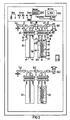
- Fig. 2 eine Frontansicht auf die als Meßschrank ausgeführte Probensammeleinrichtung mit zwei Sammelzweigen, die einander parallel geschaltet sind und jeweils eine Absorptions- und vorgeschaltete Sicherheitsflasche enthalten, sowie mit frontseitiger Anzeige- und Bedienungsplatine; und
- Fig. 3 den Schaltplan den elektrischen Meß-und Überwachungsschaltung in schematischer Blockdarstellung.
- Der pneumatische Eingang der in Fig. 1 dargestellten und als Ganzes mit PSE bezeichneten Probensammeleinrichtung ist über die Ansaugleitung 10 und ein vorgeschaltetes Feinfilter FO an den Abluftkamin eines Kernkraftwerkes oder allgemein einer kerntechnischen Anlage (Labor, Wiederaufarbeitungsanlage) angeschlossen. Die Ansaugleitung 10 verzweigt sich in die beiden Ansaugzweige i11, i12, deren jeder eine Reiheschaltung aus Gaspumpe P1 bzw. P2 und einem Absperrventil V1 bzw. V2 enthält. Einer der beiden Ansaugzweige, z. B. 111, ist in Betrieb, der andere dient als Reservezweig und wird im Falle der Störung und Abschaltung des in Betrieb befindlichen Ansaugzweiges automatisch eingeschaltet, so daß die Störung im kranken Ansaugzweig beseitigt, z. B. die Gaspumpe P1 ausgewechselt werden kann. Die Gaspumpen P1, P2 sind bevorzugt Membranverdichter-Vakuumpumpen, und zwar von solcher Bauart, bei der das Pumpengehäuse aus hochwertigen, chemisch beständigen Kunststoffteilen besteht. Der Membranantrieb erfolgt durch einen Spaltpolmotor mittels Exzenter. Die Pumpe ist wellendichtungsfrei, dadurch völlig gasdicht. Durch Einsatz besonderer Lager hat sie einen sehr geräuscharmen Lauf. Sie ist insbesondere sehr laufruhig, hat kleine Abmessungen und ist für den Dauerbetrieb geeignet.
- Im allgemeinen gewährleisten zwei parallele Ansaugzweige eine ausreichende Redundanz für einen kontinuierlichen Betrieb; in Sonderfällen könnten auch mehr als zwei parallele Ansaugzweige 11 vorgesehen sein, wenn die Probennahme-Zeiträume länger als drei Monate dauern und/oder wenn bei Ausfall eines Ansaugzweiges dieser nicht sofort repariert werden soll. Es wurde angenommen, daß der Ansaugzweig 111 in Betrieb ist. Dann wird durch die Gaspumpe P1 ein Gasstrom go von z. B. ca. 3 I/min aus dem Abgaskamin entnommen und dem Verzweigungspunkt 3 zugeführt (die Anschlußpunkte des Ansaugzweiges 112 an die Ansaugleitung 10 werden mit 1 und 2 bezeichnet). Von diesem Verzweigungspunkt 3 wird der größte Anteil des Gasstromes go als Hauptstrom gA über eine staudruckerzeugende Kanalverengung K und eine Rückführleitung 16 in den Abluftkamin zurückgeführt, d.h. die Rückspeisung erfolgt über das Leitungsstück 17.
- Die Kanalverengung K ist eine sogenannte Bypaß-Kapillare, die bei einem Durchsatz von etwa 2,9 1/min für einen Staudruck am Verzweigungspunkt 3 von etwa 0,4 bar sorgt, der für die Funktion des noch zu erläuternden Steuerventils V3, welches den Meßgasstrom gB steuert, erforderlich ist. Der Verzweigungspunkt 3 führt also den Staudruck als BezUgsdruck, und von ihm wird der kleinere Anteil des Gasstromes von z. B. 50 cm3/min als Meßgasstrom über das bereits erwähnte, die Durchflußmenge pro Zeiteinheit angenähert konstanthaltendes Stellventil V3 und einen Mengenstromzähler MDM in Form eines Massendurchflußmessers, vorzugsweise thermischen Massendurchflußmessers, sowie über ein Umschaltventil V4 durch einen der beiden Sammelzweige 141 oder 142 hindurchgeleitet. Das Umschaltventil V4 ist ein hand- oder elektromagnetbetätigtes Dreiwegeventil; die dargestellte Schaltstellung III ist eine Zwischenstellung, welche der Steuerkörper des Ventils einnimmt, wenn das Ventil von seiner Stellung I (Sammelzweig 141 eingeschaltet) in seine Stellung II (Sammelzweig 142 eingeschaltet) umgeschaltet werden soll.
- Der erste Sammelzweig 141 enthält die Reihenschaltung aus dem eigentlichen, ein Natronlaugenbad enthaltenden Sammelgefäß A1 und einem diesem Sammelgefäß A1 vorgeschalteten Sicherheitsgefäß S1. Sammel-und Sicherheitsgefäß A1, S1 werden in bevorzugter Ausführung als Absorptionsflasche und als Sicherheitsflasche ausgefürt, wie weiter unten noch erläutert. Der Natronlaugespiegel im Sammelgefäß A1 ist mit N bezeichnet, entsprechend auch beim Sammelgefäß A2 im zweiten Sammelzweig 142. Dem Sammelgefäß A1 ist im ersten Sammelzweig 141 ein Absperrventil VA1 nachgeschaltet, welches vor Entnahme des Sammelgefäßes A1 geschlossen wird. Außerdem ist ein Belüftungsventil VB1, das man auch als Druckausgleichsventil bezeichnen könnte, dem Sicherheitsgefäß S1 vorgeschaltet, damit beim Entkuppeln oder Entnehmen des Sammelgefäßes A1 nicht ein plötzlicher Abbau eines etwaigen Unterdruckes auftreten kann, der zum Verspritzen von Natronlauge führen könnte. Parallel zum ersten Sammelzweig 141 ist der zweite Sammelzweig 142 geschaltet, der gleichartig zum ersten Sammelzweig aufgebaut ist, nämlich in Reihe zum Sicherheitsgefäß S2 das Sammelgefäß A2 mit Natronlaugebad und diesem nachgeschaltet das Absperrventil VA2 enthält, ferner das Belüftungsventil VB2, angeschlossen an den zum Sicherheitsgefäß S2 führenden Leitungsteil.
- Mindestens ein solcher zweiter Sammelzweig 142 muß entweder, wie dargestellt, fest installiert sein, damit bei Beendigung des Probennahme-Intervalls für das erste Sammelgefäß A1 sofort umgeschaltet werden kann. Auf jeden Fall muß aber das zweite gleichartige Sammelgefäß A2 kurz vor Entnahme des ersten Sammelgefäßes A1 zur Verfügung stehen, d.h. eingefügt sein und mittels des Umschaltventils V4 in den Meßgasstrom gB einschaltbar sein. Im allgemeinen genügen zwei parallele Sammelzweige I4, es können aber in Sonderfällen auch mehr als zwei parallele Sammelzweige vorgesehen sein. Wesentlich ist jedenfalls, daß die Meßgasmenge gB auf die Natronlaugenmenge im jeweiligen Sammelgefäß A1, A2 so abgestimmt ist, daß während des vorgegebenen Probennahme-Intervalls, das im vorliegenden Fall im allgemeinen drei Monate beträgt, die Natronlauge im betreffenden Sammelgefäß nicht gewechselt oder ergänzt werden muß. Nach Durchströmen des einen, gerade eingeschalteten bzw. in Betrieb befindlichen Sammelzweiges 141 oder 142 strömt das Meßgas gB über den Verzweigungspunkt 5 in die Rückführleitung 15, wobei es den größten Anteil von 14C02 im Natronlaugebad N1 verloren hat; der Abscheidegrad liegt beim dargestellten Beispiel bei mehr als 99 %. Dieses entreicherte Meßgas ist mit g'B bezeichnet, es fließt ebenso wie der Hauptstrom 9A dem Verzweigungspunkt 6 zu und von da zusammen mit dem Hauptstrom 9A über das letzte Leitungsstück 17 zurück zum Kamin. Wie es Fig. 2 zeigt, sind die Sammelgefäße A1, A2 in den beiden Sammelzweigen 14 nach Fig. 1 jeweils als Absorptionsflaschen ausgeführt, welche ein in etwa zentrisch angeordnetes, durch den Flaschenkopf a1 und Flaschenhals a2 sowie durch die Absorptionsflüssigkeit N1 zum Flaschenboden a3 führendes und dort mit einem Gasverteilkopf bzw. einer Fritte a4 versehenes Meßgaseinleitrohr a0 aufweisen. Oberhalb des Absorptionsflüssigkeitsspiegels, auch abgekürzt als "Badspiegel" N zu bezeichnen, ist zwecks leichter De- und Remontage des Flaschenkörpers a5 mit dem Laugenbad N1 eine lösbare, gasdichte Flanschverbindung a6 zwischen Kopf a1 und Hals a2 angeordnet, welche als Sicherung gegen Verbacken der aufeinander gepreßten Dichtflächen von Flaschenhals a2 und -kopf a1 dazwischengelegte Teflon-Dichtungsscheiben a61 aufweist. Die Absorptions- und die Sicherheitsflasche Al, S1 bestehen insbesondere aus laugen- und säuereresistentem Glas, wobei das im Flanschbereich feingeschliffene Glas ohne Dichtungszwischenlagen besonders zum Haften oder Zusammenbacken neigen würde. Vom Flaschenkopf a1 führt die an diesen angeschlossene Meßgasrückleitung a7 zum Absperrventil VA1. Der Absorptionsflasche A1 ist eine normalerweise von Absorptionsflüssigkeit freie Sicherheitsflasche S1 gasströmungsmäßig vorgeschaltet, wie auch schon aus dem Schaltbild nach Fig. 1 erkennbar. Deren Gaszufürleitung l41 ist an den Flaschenkopf s1 angeschlossen, und die Gasverbindungsleitung s0 zur nachgeschalteten Absorptionsflasche A1 besteht aus einem mit dem Meßgaseinleitrohr a0 kommunizierenden, in etwa zentrisch in der Sicherheitsflasche angeordneten Verbindungsrohr, welches kurz oberhalb des Flaschenbodens s3 eine Einlaßmündung s4 hat und durch den Flaschenkopf s1 herausgeführt ist. Mit 10 ist eine gasdichte Kupplungshülse zwischen dem Verbindungsrohr s0 und dem Meßgaseinleitrohr a0 bezeichnet, weitere gasdichte Kupplungshülsen sind im Zuge der Leitung 141 vor der Sicherheitsflasche S1 und in der Leitung a7 hinter der Absorptionsflasche A1 angeordnet und mit 11 bzw. 12 bezeichnet. Auch die Sicherheitsflasche S1 weist eine gasdichte Flanschverbindung s6 auf, die analog zu derjenigen der Absorptionsflasche A ausgegebildet ist. Beide Flaschen A1 und S1 sind mittels zangenartiger Halteschellen 13, welche in ihrem Halsbereich a2 bzw. s2 angreifen, gehaltert. Diese Schellen gestatten ein bequemes De- und Remontieren der Flaschen A1, S1 gegebenenfalls in Verbindung mit den Flanschverbindungen a6, s6. Letztere weisen Spannringe a62 bzw. s62 auf, welche die Ringflansche am Flaschenhals a2 und am Flaschenkopf a1 hintergreifen und durch flaschenaxiale Spannschrauben 14 zueinander verspannbar sind, so daß zusammen mit den eingelegten Teflonringen a61 die Ringflansche völlig gasdicht aufeinander gepreßt werden können. Die Spannschrauben 14 sind über den Umfang der Spannringe a62 verteilt.
- Das Meßgaseinleitrohr a0 trägt an seinem unteren Ende den schon erwähnten tellerförmigen Gasverteilkopf bzw. die Fritte a4, welcher mit einem nach oben gerichtete Auslaßöffnungen aufweisenden Düsenkranz versehen ist. Die Auslaßöffnungen sind bei a8 angedeutet. Sie sind unterhalb des Mundstückes a91 einer Gasverzögerungsspirale a9 angeordnet. Letztere umschlingt das Meßgaseinleitrohr a0 und weist im oberen Flaschenbereich, jedoch in der Regel noch unterhalb des Spiegels N des Laugenbades N1, seine Auslaßöffnung a92 auf. Durch den Düsenkranz der Öffnungen a8 wird der durch das Meßgaseinleitrohr a0 zugeführte Meßgasstrom in feine Blasen unterteilt, die von dem trichterförmigen Mundstück a91 aufgefangen und durch die Rohrspirale a9, auch als wendelförmig ausgebildetes Steigrohr zu bezeichnen, aufwärts perlen. Ohne die Rohrspirale wäre die Gasweglänge im Laugenbad höchstens so lang wie die Eintauchhöhe des Meßgaseinleitrohres a0. Durch das wendelförmige Steigrohr bzw. die Gasverzögerungespirale a9 wird die Gasweglänge mehr als vervierfacht und somit eine lange Verweilzeit des Gases erreicht. Die Natronlauge in der Rohrspirale wird durch die aufsteigenden Gasblasen mitgenommen und durch Natronlauge aus dem Reservoir der Flasche A1 ersetzt, d.h. es findet ein Umwälzvorgang statt, der eine lokale Übersättigung verhindert. Diese Umwälzvorgang für die Natronlauge wäre auch dann noch gegeben, wenn durch Wasseraustrag der Laugenfüllstand unter das obere Ende der Rohrspirale absinken sollte.
- Wie in der Einleitung bereits erwähnt, ist durch die der Absorptionsflasche A1 gasströmungsmäßig vorgeschaltete Sicherheitflasche S1, die normalerweise leer ist, gewährleistet, daß im Falle eines Überdruckes auf der Abströmseite der Flaschenkolonne S1-A1 Natronlauge keinesfalls austreten kann, sondern lediglich über das Meßgaseinleitrohr a0, die Rohrkupplung 10 und das Verbindungsrohr s0 in die Sicherheitsflasche S1, so lange der Überdruck besteht, gedrückt wird. Von der Sicherheitsflasche kann ein Austritt der Natronlauge in ihre Gaszuströmleitung keinesfalls erfolgen, sondern überschüssiges Gas perlt dann durch das in die Sicherheitsflasche S1 gedrückte Laugen-Reservoir. Bei Beendigung dieser anormalen Druckumkehr und Rückkehr zu normalen Druckverhältnissen, bei welchen der zuströmseitige Druck der Flaschenkolonne S1-A1 wieder größer als der abströmseitige ist, wird die Natronlauge aus der Sicherheitsflasche wieder in die Absorptionsflasche zurückgedrückt, abgesehen von einem kleinen Rest, dessen Höhe durch den Abstand des Mundstückes s4 vom Boden s3 der Sicherheitsflasche S1 gegeben ist. Die Flaschenkolonne S2-A2 im zweiten Sammelzweig 142, welche im unteren Teil der Fig. 2 dargestellt ist, ist gleichartig zur oberen Flaschenkolonne S1-A1 ausgebildet, weshalb von einer näheren Erläuterung abgesehen werden kann. Bei V4 erkennt man noch den Kippschalter des Umschaltventils V4 (vgl. Fig. 1). Mit 15.1 bzw. 15.2 sind Kontroll-Lampen bezeichnet, welche anzeigen, ob der betreffende Sammelzweig 141 oder 142 in Betrieb ist. Die im oberen Teil des Meßschrankes nach Fig. 2 dargestellte Anzeige-und Bedienungsplatine wird erst verständlich nach Erläuterung der elektrischen Meß- und Überwachungsschaltung nach Fig. 3.
- Gemäß Fig. 3 ist dem in der Meßleitung 13 nach dem Stellventil V3 angeordneten Massendurchflußmesser MDM (vgl. Fig. 1), welcher eine dem Massendurchfluß analoge Meßspannung erzeugt, ein elektronischer Regler RE über die Meßleitung e1 und eine mit Anzeigesowie Auswerteelektronik bezeichnete Baueinheit AAE sowie die Meßleitung e2 nachgeschaltet. Diesem wird die Meßspannung, gegebenenfalls nach Verstärkung, als Durchfluß-Istwert und ein mittels eines SollwertPotentiometers PO einstellbarer Durchfluß-Sollwert über Meßleitung e3 zugeleitet. Die im Regler RE gebildete Soll-Istwert-Differenz wird dann über die Signalleitung e4 als Stellgröße dem Stellventil V3 zugeleitet. Die zwischen dem Massendurchflußmesser MDM und dem Regler RE geschaltete Baueinheit AAE "Anzeige- und Auswerteelektronik" weist eine mindestens dreistellige Digitalanzeige für den Momentanwert des Massendurchflusses auf. Dem Baustein AAE ist weiterhin über Signalleitung e5 ein Spannung/lmpuls-Umwandler U/f nachgeschaltet, der über Impulsleitung e6 ein elektromechanisches Zählwerk EMZ steuert. Letzteres summiert die Teilmengen der Meßperiode zur Gesamtdurchflußmenge auf. Im dargestellten Beispiel ist dieses Zählwerk EMZ siebenstellig. Über Signalleitung e7 sind dem Baustein AAE noch mindestens zwei Alarmeinrichtungen nachgeschaltet, die bei Ober- bzw. Unterschreiten eines eingestellten Durchflußmengenwertes Störmeldung geben. Die beiden Alarmeinrichtungen sind mit SM1 und SM2 bezeichnet, sie liegen in den beiden Signalzweigen e71 und e72. Im Falle einer Störmeldung durch SM1 oder durch SM2 wird unterstellt, daß der gerade in Betrieb befindliche Ansaugzweig, 111 oder 112 gestört ist. Deshalb wird dieser "kranke" Zweig abgeschaltet durch Schließen seines Absperrventils V1 oder V2 und Abstellen der betreffenden Gaspumpe, und der andere, parallelgeschaltete "gesunde" Zweig wird eingeschaltet. In diesem Zustand kann dann der Störung im "kranken" Zweig nachgegangen und gegebenenfalls die defekte Gaspumpe repariert oder ausgewechselt werden. Mit NT ist in Fig. 3 noch der Netzteil bezeichnet, von dem die Stromversorgungsleitungen e81 - e84 zu den einzelnen Bausteinen der Meß- und Überwachungsschaltung nach Fig. 3 führen, nämlich zu den Alarmeinrichtungen SM1, SM2, zu dem Umwandler U/f, zu dem Baustein AAE und zum Regler RE. Die in Fig. 3 dargestellten Bausteine der elektronischen Schaltung kehren zum Teil auf der frontseitigen Meß- und Bedienungsplatine in Fig. 2 wieder. Der Massendurchflußmesser MDM ist bevorzugt ein thermischer Massendurchflußmesser. Dieser besteht im allgemeinen (nicht näher dargestellt) aus einem Edelstahlrohr mit einer Heizwicklung in der Mitte und zwei beiderseits angeordneten Meßwicklungen. Die in der Heizwicklung erzeugte Wärmemenge wird von dem Fluid zu den Meßwicklungen geleitet. Die dort auftretende Temperaturdifferenz steigt mit der Durchflußmenge von Null bis zu einem Maximalwert an und wird in der Auswerteelektronik AAE mit einer empfindlichen Brückenschaltung gemessen. Da der Wärmetransport an die Massenteilchen gebunden ist, verhält sich der Meßwert proportional zur durchströmenden Masse. Die Heiz- und Meßwicklungen sind so angebracht, daß sie nicht direkt mit dem durchströmenden Medium in Berührung kommen und damit gegen einen eventuellen korrosiven Angriff geschützt sind. Die in der Brückenschaltung (nicht näher dargestellt) erzeugte Spannung wird in der Auswerteelektronik AAE verstärkt. Die Ausgangsspannung beträgt Null bis 5 Volt. Der Momentanwert wird mit der in Fig. 3 dargestellten dreistelligen Digitalanzeige angezeigt. Die von dem Spannungs/Impuls-Umwandler U/f erzeugten Impulse betreiben das schon erwähnte siebenstellige elektromechanische Zählwerk. Bei einem eventuellen Netzausfall werden die gesamte Elektronik und die Pumpenspannung ausfallen, der Gesamtdurchflußwert bleibt aber in dem elektromechanischen Zählwerk erhalten. Tritt die Netzspannung wieder auf, läuft die Pumpe an, die Mengenregelung wird wieder aktiv, und zu dem ursprünglichen Integralwert werden die neuen Ergebnisse addiert. Das Durchflußmeßsignal dient, wie bereits erwähnt, dazu, bei Über- bzw. Unterschreiten eines eingestellten Wertes durch potentialfreie Kontakte Störmeldung zu geben (Anzeige am Gerät und an der Warte). Beim Unterschreiten des Minimalwertes wird - wenn man unterstellt, daß der Ansaugzweig 111 in Betrieb ist - die Reservepumpe P2 eingeschaltet und das Ventil V2 geöffnet. Die Pumpe P1 wird ausgeschaltet und Ventil V1 geschlossen.
- Bei ordnungsgemäßem Betrieb der Probensammeleinrichtung PSE wird in der eingeschalteten Absorptionsflasche A1 bzw. A2 das Kohlenoxid aus dem Meßgasstrom weitgehend in der Natronlauge zurückgehalten, und zwar mit einem Abscheidegrad von > 99 %. Beim vierteljährlichen Probenwechsel wird - während der eine Sammelzweig noch in Betrieb ist - der andere Sammelzweig frisch präpariert, d.h. die im Labor mit einer Menge von z. B. rund 900 g frischer 0,5 Mol/I-Natronlauge gefüllte Absorptionsflasche eingebaut. Danach wird über das Ventil V4 umgeschaltet und somit eine unterbrechungsfreie Probensammlung gewährleistet. Aus der abgeschalteten Absorptionsstrecke wird die Absorptionsflasche mit der Sammelprobe ausgebaut. Die weitere Verarbeitung der Sammelprobe erfolgt dann im Labor unter geeigneten Arbeitsbedingungen, so daß am Standort der Probensammeleinrichtung nicht mit Absorptionsmittel gearbeitet zu werden braucht. Je nach den Laborgegebenheiten kann dann die C-14-Messung und -Auswertung über eines der folgenden Verfahren erfolgen:
- - Direkte LSC-Messung der Absorberlösung (LSC = liquid scintillation counter);
- - β-Festpräparatmessung nach BaC03-Fällung;
- - LSG-Messung als BaC03-Suspension.
Claims (10)
gekennzeichnet durch die folgenden Merkmale:
Applications Claiming Priority (2)
| Application Number | Priority Date | Filing Date | Title |
|---|---|---|---|
| DE3321092 | 1983-06-10 | ||
| DE3321092A DE3321092A1 (de) | 1983-06-10 | 1983-06-10 | Probensammeleinrichtung fuer in der umgebungsluft enthaltene gasfoermige radioaktive stoffe |
Publications (2)
| Publication Number | Publication Date |
|---|---|
| EP0129113A1 EP0129113A1 (de) | 1984-12-27 |
| EP0129113B1 true EP0129113B1 (de) | 1987-10-14 |
Family
ID=6201210
Family Applications (1)
| Application Number | Title | Priority Date | Filing Date |
|---|---|---|---|
| EP84106100A Expired EP0129113B1 (de) | 1983-06-10 | 1984-05-29 | Probensammeleinrichtung für in der Umgebungsluft enthaltene gasförmige radioaktive Stoffe |
Country Status (3)
| Country | Link |
|---|---|
| EP (1) | EP0129113B1 (de) |
| JP (1) | JPS6013278A (de) |
| DE (2) | DE3321092A1 (de) |
Families Citing this family (5)
| Publication number | Priority date | Publication date | Assignee | Title |
|---|---|---|---|---|
| CN108458913B (zh) * | 2018-01-22 | 2023-06-27 | 中国地质大学(武汉) | 一种弱透水层孔隙水的14c提取装置和方法 |
| CN108709780A (zh) * | 2018-06-06 | 2018-10-26 | 青岛海纳光电环保有限公司 | 环境空气二噁英采样仪 |
| CN112378713B (zh) * | 2020-11-16 | 2023-03-17 | 三门核电有限公司 | 一种提高核电厂核岛烟囱c-14取样装置运行可靠性的方法 |
| CN114199630B (zh) * | 2021-11-25 | 2024-12-13 | 中国船舶重工集团公司第七一九研究所 | 一种用于事故及事故后气溶胶、碘、惰性气体取样装置 |
| CN116609142A (zh) * | 2023-06-16 | 2023-08-18 | 广州工乐科技有限公司 | 一种带气路切换的采样器及采样方法 |
Family Cites Families (14)
| Publication number | Priority date | Publication date | Assignee | Title |
|---|---|---|---|---|
| DE1209776B (de) * | 1964-06-12 | 1966-01-27 | Dr Helmut F Simon | Verfahren und Vorrichtung zur Messung der Radioaktivitaet C- und/oder H-markierter Verbindungen |
| DE1489925A1 (de) * | 1965-07-01 | 1969-09-04 | Kernforschung Gmbh Ges Fuer | Verfahren und Vorrichtung zum Messen der Aktivitaet eines vorbestimmten Stoffes in einem mehrere radioaktive Stoffen enthaltenden Stoffgemisch |
| JPS4915132B1 (de) * | 1969-10-01 | 1974-04-12 | ||
| US3653399A (en) * | 1970-06-15 | 1972-04-04 | Nat Instr Lab Inc | Gas flow controlling system |
| JPS5419903Y2 (de) * | 1971-04-15 | 1979-07-20 | ||
| DE2251189C2 (de) * | 1972-10-19 | 1982-06-09 | Herfurth Gmbh, 2000 Hamburg | Verfahren zum selektiven Messen des in elementarer oder chemisch gebundener Form vorliegenden Jodnuklides ↑1↑↑3↑↑1↑ J |
| JPS5720691A (en) * | 1980-07-15 | 1982-02-03 | Tokyo Shibaura Electric Co | Radioactive off-gas monitor system |
| JPS5519395B2 (de) * | 1974-01-25 | 1980-05-26 | ||
| US3982129A (en) * | 1974-11-22 | 1976-09-21 | The United States Of America As Represented By The United States Energy Research And Development Administration | Method and means of monitoring the effluent from nuclear facilities |
| JPS5419001A (en) * | 1977-07-13 | 1979-02-13 | Ebara Corp | Drain recovery system |
| GB2037180B (en) * | 1978-11-17 | 1982-11-24 | Mini Agriculture & Fisheries | Gas bubbler for atmospheric sampling |
| JPS5574439A (en) * | 1978-11-29 | 1980-06-05 | Toshiba Corp | Carbon dioxide absorbing liquid injection device to carbon dioxide absorber |
| JPS55134372A (en) * | 1979-04-06 | 1980-10-20 | Hitachi Ltd | Dust radiation concentration surveillance device |
| JPS5712398A (en) * | 1980-06-27 | 1982-01-22 | Tokyo Shibaura Electric Co | Off-gas system for atomic power plant |
-
1983
- 1983-06-10 DE DE3321092A patent/DE3321092A1/de not_active Withdrawn
-
1984
- 1984-05-29 DE DE8484106100T patent/DE3466823D1/de not_active Expired
- 1984-05-29 EP EP84106100A patent/EP0129113B1/de not_active Expired
- 1984-06-08 JP JP59118055A patent/JPS6013278A/ja active Pending
Also Published As
| Publication number | Publication date |
|---|---|
| DE3466823D1 (en) | 1987-11-19 |
| JPS6013278A (ja) | 1985-01-23 |
| EP0129113A1 (de) | 1984-12-27 |
| DE3321092A1 (de) | 1984-12-13 |
Similar Documents
| Publication | Publication Date | Title |
|---|---|---|
| DE60127482T2 (de) | Wasserreinigung System mit Messung und Steuerung der Abgabe | |
| EP0064159B1 (de) | Prüfeinrichtung für Filter, insbesondere Sterilfilter | |
| EP0065271B1 (de) | Verfahren zum Mischen von Gasen in einem vorgegebenen Verhältnis und zum Dosieren der Gasmischung | |
| DE2614787C3 (de) | Vorrichtung zum Entnehmen von Fliissigkeitsproben | |
| DE1598068B2 (de) | Vorrichtung zur selbsttaetigen fortlaufenden probenahme von abgasen | |
| EP0224692A2 (de) | Vorrichtung zur emissionsfreien Probenahme von leicht verdampfbaren Flüssigkeiten | |
| DE3020845A1 (de) | Verfahren und anordnung zum beschicken von rohrreaktoren mit koernigen feststoffen | |
| DE2455751B2 (de) | Verfahren zum Mischen von Druckgasen und ein Gasmischgerät dazu | |
| DE3422062A1 (de) | Verfahren zur langzeitbestimmung und dauerueberwachung des schadstoffgehaltes von feststoffbeladenen abgasstroemen | |
| DE3229328A1 (de) | Gasdosiervorrichtung fuer medizinische apparate | |
| EP0129113B1 (de) | Probensammeleinrichtung für in der Umgebungsluft enthaltene gasförmige radioaktive Stoffe | |
| DE2828153C3 (de) | Kernreaktor mit einem flüssigen Kühlmittel | |
| DE102018130652A1 (de) | Vorrichtung und Verfahren zum Befüllen eines Behälters | |
| DE3545160C2 (de) | ||
| DE3538449C2 (de) | ||
| DE2501733C3 (de) | Verfahren zur Ermittlung der Umschaltpunkte für Mischflüssigkeiten bei FUtrationsprozessen | |
| DE1927551B2 (de) | Vorrichtung zur Prüfung eines Behälters oder einer Anschlußeinrichtung auf Gasdichtheit | |
| EP0550523B1 (de) | Verfahren und vorrichtung zur probengewinnung und probenhandhabung | |
| EP0247365A2 (de) | Vorrichtung zum Füllen von Sauerstoffbehältern für die Verwendung bei der medizinischen Sauerstoff-Therapie | |
| DE4015336A1 (de) | Vorrichtung zum reinigen von wasser nach dem umkehrosmose-verfahren | |
| CH639566A5 (de) | Dosiergeraet zur dosierung einer gaszugabe in fluessigkeiten. | |
| DE3210465A1 (de) | Vorrichtung zur erfassung der menge der von einer kuh bei einem melkvorgang abgegebenen milch | |
| DE102015015150B4 (de) | Gasmesssystem mit einer Gasmessvorrichtung und einer Kontrolleinrichtung und Verfahren zum Betrieb einer Gasmessvorrichtung mittels einer Kontrolleinrichtung | |
| CH635757A5 (en) | Apparatus for metering a liquid additive into a bulk liquid | |
| EP0526805B1 (de) | Vorrichtung mit Abzweigungen zur Pulverförderung |
Legal Events
| Date | Code | Title | Description |
|---|---|---|---|
| PUAI | Public reference made under article 153(3) epc to a published international application that has entered the european phase |
Free format text: ORIGINAL CODE: 0009012 |
|
| AK | Designated contracting states |
Designated state(s): CH DE FR GB LI SE |
|
| 17P | Request for examination filed |
Effective date: 19841026 |
|
| 17Q | First examination report despatched |
Effective date: 19860421 |
|
| GRAA | (expected) grant |
Free format text: ORIGINAL CODE: 0009210 |
|
| RAP1 | Party data changed (applicant data changed or rights of an application transferred) |
Owner name: SIEMENS AKTIENGESELLSCHAFT BERLIN UND MUENCHEN |
|
| AK | Designated contracting states |
Kind code of ref document: B1 Designated state(s): CH DE FR GB LI SE |
|
| REF | Corresponds to: |
Ref document number: 3466823 Country of ref document: DE Date of ref document: 19871119 |
|
| ET | Fr: translation filed | ||
| GBT | Gb: translation of ep patent filed (gb section 77(6)(a)/1977) | ||
| PLBE | No opposition filed within time limit |
Free format text: ORIGINAL CODE: 0009261 |
|
| STAA | Information on the status of an ep patent application or granted ep patent |
Free format text: STATUS: NO OPPOSITION FILED WITHIN TIME LIMIT |
|
| 26N | No opposition filed | ||
| PGFP | Annual fee paid to national office [announced via postgrant information from national office to epo] |
Ref country code: SE Payment date: 19910522 Year of fee payment: 8 |
|
| PGFP | Annual fee paid to national office [announced via postgrant information from national office to epo] |
Ref country code: CH Payment date: 19910823 Year of fee payment: 8 |
|
| PGFP | Annual fee paid to national office [announced via postgrant information from national office to epo] |
Ref country code: GB Payment date: 19920424 Year of fee payment: 9 |
|
| PG25 | Lapsed in a contracting state [announced via postgrant information from national office to epo] |
Ref country code: SE Effective date: 19920530 |
|
| PG25 | Lapsed in a contracting state [announced via postgrant information from national office to epo] |
Ref country code: LI Effective date: 19920531 Ref country code: CH Effective date: 19920531 |
|
| REG | Reference to a national code |
Ref country code: CH Ref legal event code: PL |
|
| PG25 | Lapsed in a contracting state [announced via postgrant information from national office to epo] |
Ref country code: GB Effective date: 19930529 |
|
| GBPC | Gb: european patent ceased through non-payment of renewal fee |
Effective date: 19930529 |
|
| EUG | Se: european patent has lapsed |
Ref document number: 84106100.5 Effective date: 19921204 |
|
| PGFP | Annual fee paid to national office [announced via postgrant information from national office to epo] |
Ref country code: FR Payment date: 19950522 Year of fee payment: 12 |
|
| PGFP | Annual fee paid to national office [announced via postgrant information from national office to epo] |
Ref country code: DE Payment date: 19950720 Year of fee payment: 12 |
|
| PG25 | Lapsed in a contracting state [announced via postgrant information from national office to epo] |
Ref country code: FR Effective date: 19970131 |
|
| PG25 | Lapsed in a contracting state [announced via postgrant information from national office to epo] |
Ref country code: DE Effective date: 19970201 |
|
| REG | Reference to a national code |
Ref country code: FR Ref legal event code: ST |