EP0129164B1 - Châssis de cycle pliable - Google Patents
Châssis de cycle pliable Download PDFInfo
- Publication number
- EP0129164B1 EP0129164B1 EP84106578A EP84106578A EP0129164B1 EP 0129164 B1 EP0129164 B1 EP 0129164B1 EP 84106578 A EP84106578 A EP 84106578A EP 84106578 A EP84106578 A EP 84106578A EP 0129164 B1 EP0129164 B1 EP 0129164B1
- Authority
- EP
- European Patent Office
- Prior art keywords
- center tube
- bicycle frame
- bolt
- lever
- center
- Prior art date
- Legal status (The legal status is an assumption and is not a legal conclusion. Google has not performed a legal analysis and makes no representation as to the accuracy of the status listed.)
- Expired
Links
Images







Classifications
-
- B—PERFORMING OPERATIONS; TRANSPORTING
- B62—LAND VEHICLES FOR TRAVELLING OTHERWISE THAN ON RAILS
- B62K—CYCLES; CYCLE FRAMES; CYCLE STEERING DEVICES; RIDER-OPERATED TERMINAL CONTROLS SPECIALLY ADAPTED FOR CYCLES; CYCLE AXLE SUSPENSIONS; CYCLE SIDECARS, FORECARS, OR THE LIKE
- B62K15/00—Collapsible or foldable cycles
- B62K15/006—Collapsible or foldable cycles the frame being foldable
-
- Y—GENERAL TAGGING OF NEW TECHNOLOGICAL DEVELOPMENTS; GENERAL TAGGING OF CROSS-SECTIONAL TECHNOLOGIES SPANNING OVER SEVERAL SECTIONS OF THE IPC; TECHNICAL SUBJECTS COVERED BY FORMER USPC CROSS-REFERENCE ART COLLECTIONS [XRACs] AND DIGESTS
- Y10—TECHNICAL SUBJECTS COVERED BY FORMER USPC
- Y10T—TECHNICAL SUBJECTS COVERED BY FORMER US CLASSIFICATION
- Y10T403/00—Joints and connections
- Y10T403/32—Articulated members
- Y10T403/32254—Lockable at fixed position
- Y10T403/32262—At selected angle
- Y10T403/32319—At selected angle including pivot stud
- Y10T403/32368—At selected angle including pivot stud including radial interengaging tongue and slot or serrations
Definitions
- This invention relates to an improvement of a foldable bicycle frame according to the features of the introduction part of claim 1.
- FR-A-973 308 discloses a foldable bicycle frame comprising a substantially vertical center tube at a mid portion of a bicycle frame, an upper center tube and a lower center tube to be partially fitted in upper and lower ends of said center tube, respectively, to form a front half of the bicycle frame including said center tube and a rear half of the bicycle frame including said upper and lower center tubes, radially annularly arranged continuous V-shaped teeth on connection surfaces of said upper and lower center tubes and said center tubes, and clamping means for clamping said center tube and said upper and lower center tubes in engagement with said teeth on said connection surfaces, thereby enabling said bicycle frame to be foldable by releasing and then clamping said center tubes.
- This known foldable bicycle frame needs many reinforcing members and folding locations so that the bicycle of this citation is complicated and heavy.
- the folding operation of the bicycle of this citation is very complicated.
- the style of the bicycle of this citation is thick-headed which is out of the question of the sports bicycle of the captioned case.
- the upper and lower center tubes are moved upward or downward in relationship to the center tube. It is furthermore an advantage to fix the seat supporting tube on the upper center tube and the chain stays on the lower center tube respectively, while the front tubes are connected in a fixed manner to the center tube as part of the front frame part. With such a construction however, the two upper and lower center tubes are only moveable upwards and downwards in order to provide the foldability.
- the seat stays are pivotally connected to the seat supporting tube and the chain stays at their two ends respectively.
- the seat tube is brought to the center of the bicycle as a hinge tube which is the center tube.
- the seat tube is connected to the center tube through the upper center tube.
- the foldable bicycle frame according to the invention further comprises positioning means for positioning the front and rear halves in extended and folded conditions
- the positioning means comprises the fitted portions of the upper and lower center tubes in the center tube, the fitted portions being fitted with each other, the center tube and the fitted portions being formed with elongated slots respectively aligned with each other in extended and folded positions of the bicycle frame, a lever pivotally mounted to the center tube in a manner a free end of the lever is in opposition to the elongated slot of the center tube, a positioning pin secured to the free end of the lever so as to passing through the elongated slots aligned in the extended and folded positions, and urging means for normally urging the lever toward the center tube.
- the clamping means comprises an intermediate disc integral with the lower center tube and formed with a bolt-passing aperture substantially at its center, a lower disc integral with the upper center tube and formed with a bolt-passing aperture substantially at its center, a spring located in compression between the intermediate and lower discs, a bolt extending through the intermediate and lower discs beyond above the upper center tube, a lever pivotally secured to an upper end of the bolt extending above the upper center tube, at least one cam interlocked with the lever and engaging the upper center tube so that pivotal movement of the lever causes the engagement of the teeth to be clamped and released.
- the lever comprises locking means which comprises an anchoring member in the form of a hook provided on the bicycle frame at a location where a free end of the lever is adjacent thereto when clamped, a lock member pivotally mounted on the lever and having a projection extending above through an opening formed in an upper surface near to the free end and an opening formed in an intermediate portion of the lock member and engaging the anchoring member, and urging means for urging the lock member against the anchoring member into engagement with each other.
- locking means comprises an anchoring member in the form of a hook provided on the bicycle frame at a location where a free end of the lever is adjacent thereto when clamped, a lock member pivotally mounted on the lever and having a projection extending above through an opening formed in an upper surface near to the free end and an opening formed in an intermediate portion of the lock member and engaging the anchoring member, and urging means for urging the lock member against the anchoring member into engagement with each other.
- upper ends of seat stays are pivotally connected to a seat tube integral with the upper center tube and lower ends of the seat stays are pivotally connected to rear ends of chain stays.
- the frame further comprises a support bar supporting the bicycle frame against falling down, a bracket for supporting the support bar pivotably into its operative position and inoperative position, the bracket being provided on its upper portion with a shaft portion capable of detachably fitting in a lower opening of the lower center tube, and fastening means for fixing the bracket to the lower center tube.
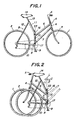
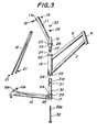
- FIGs. 1-5 illustrating a bicycle to which one embodiment of the invention is applied, which comprises a front wheel 1, a rear wheel 2, fork blades 3, a head tube 4, handle bars 5, an upper front tube 6, a lower front tube 7, a bottom bracket spindle 8, a crank 9, chain stays 10, a seat tube 11, seat stays 12, a seat pillar 13 and a saddle 14.
- a bicycle frame is provided at a mid portion with a substantially vertical center tube 15, an upper center tube 16 fitted in an upper end of the center tube 15 and a lower center tube 17 fitted in a lower end of the center tube 15.
- To an upper portion of the center tube 15 is connected a rear end of the upper front tube 6, and to a lower portion of the center tube 15 is connected a rear end of the lower center tube 7 to form a front half A of the bicycle frame.
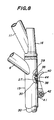
- a lower end of the seat tube 11 which is provided at an upper end with a rearward extending bracket Ila to which is connected upper ends of the seat stays 12 by means of a bolt 18 and a nut 19 as shown in Fig. 3.
- end surfaces of upper end lower flanges 22 and 23 of the center tube 15 are formed with continuous V-shaped teeth 24 radially arranged.
- An end surface of a lower flange 25 of the upper center tube 16 is formed with continuous V-shaped teeth 24 adapted to be in mesh with the above teeth 24 of the center tube 15.
- the upper center tube 16 is formed at its lower end with a downward extending cylindrical portion 26 adapted to be fitted in the center tube 15 and with a downward extending contracted cylindrical portion 27 which is continuously integrally formed with the cylindrical portion 26 and has a smaller diameter than that of the cylindrical portion 26.
- An upper cap 28 having a bolt passing aperture 28a is fixed to an upper end of the upper center tube 16.
- an end surface of an upper flange 29 of the lower center tube 17 is formed with continuous V-shaped teeth 24 adapted to be in mesh with the teeth 24 at the lower flange 23 of the center tube 15.
- the lower center tube 17 is formed at its upper end with an upward extending cylindrical portion 30 adapted to be fitted in the center tube 15.
- a bolt seat 31 having a bolt passing aperture 31 a is fixed to the inside of the cylindrical portion 30.
- a bolt 32 is inserted into the lower center tube 17 from its underside so as to extend through the passing apertures 31a a of the seat 31 and 28a of the cap 28, and then a nut 33 is threadedly engaged on an upward extending screw portion 32a of the bolt 32.
- the front and rear halves A and B of the frame can be freely rotated about a center axis 1 (Fig. 2) of the center tubes 15,16 and 17 as shown by an arrow C.
- the nut 33 is loosened so as to be retracted by a distance more than twice of a height of the V-shaped teeth 24 and then the front and rear halves are rotated relatively to each other as shown by the arrow C in Fig. 2 to move the upper and lower center tubes 16 and 17 away from the center tube 15 by an interaction between oblique faces of the V-shaped teeth 24 or a wedge action of the teeth 24 so as to release the engagement of the teeth 24.
- the rear half B of the frame sufficiently accommodates the slight upward and downward movements of the upper and lower center tubes 16 and 17 because the seat stays 12 are connected by the bolts 18 and 21 at their upper and lower ends to the rear half B of the frame.
- the front and rear halves A and B are brought into a straight or extended state as shown in Fig. 1 and then the nut 33 is tightened up.
- any one of the front and rear halves A and B is rotated about the center line 1 relatively to each other as shown in Fig. 2.
- the nut 33 is tightened.
- the foldable bicycle frame constructed as above described has the following advantages.
- Figs. 6-9 illustrate another preferred embodiment of the invention, wherein a bicycle frame comprises positioning means for exactly positioning front and rear halves of the frame in bringing them into an extended or running position and a folded position.
- front half A and rear half B of a bicycle frame are relatively pivotally moved about a center connection comprising a center tube 15 and cylindrical portions 26a and 30 of upper and lower center tubes fitted with each other.
- the center tube 15 of the front half A is formed in its side with a longitudinally elongated slots or aperture 35.
- the cylindrical portions 26a and 30 are adapted to be fitted with each other in the center tube 15 and formed in their sides with elongated slots or apertures 36 and 37, respectively, in aligned with the slot 35 of the center tube 15, when the bicycle frame is extended or under a straight condition.
- the cylindrical portions 26a and 30 are further formed in their sides with elongated slots 38 and 39, respectively, in aligned with the slot 35 when the frame is under a properly folded condition.
- a lever 40 is pivotally mounted at its one end by means of a pin 42 to a bracket 41 extending from the center tube 15 in a manner that a knock pin or positioning pin 44 formed on a free end of the lever 40 can be inserted into the elongated slot 35 and the elongated slots 36, 37, 38 and 39 aligned with the slot 35.
- a spring 43 coiled about the pin 42 always urges the lever 40 against the center tube 15.
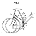
- the nut 33 is first loosened and the positioning pin 44 is then retracted or withdrawn from the elongated slots 35, 36 and 37 by pivotally moving the lever 40 away from the center tube 15. Thereafter, the front half A of the frame is rotated about the axis 1 as shown by an arrow E in Fig. 9. In this manner, when the relative angle between the front and rear halves becomes a suitable folded angle, the positioning pin 64 automatically extends into the elongated slots 35, 38 and 39 with the aid of the spring 43, because the elongated slot 35 is aligned with the slots 38 and 39 at the suitable folded angle as shown in Fig. 8, thereby maintaining the halves A and B in the suitable folded position. Accordingly, the nut 33 need not be tightened.
- the lever 40 In order to bring the bicycle from this folded condition into the extended or running condition, the lever 40 is raised away from the center tube 15 to retract or withdraw the positioning pin 44 from the elongated slots 39, 38 and 35 and thereafter the front half A is rotated forward, thereby automatically setting the bicycle frame in the straight condition.
- the positioning means constructed as above described has the following advantages.
- an inner disc 51 provided in a cylindrical portion 30 integral with the lower center tube 17 is formed centrally with a semicircular aperture 51 b in the form of a half-moon.
- a cylindrical portion 47 integral with an upper center tube 16 is provided at its lower end with a lower disc 54 formed in its center with a bolt passing aperture 54a.
- a coil spring 55 is arranged in compression between an intermediate disc 51 integral with a lower center tube 17 and the lower disc 54 integral with the upper center tube 16.
- a bolt 56 is formed on one side of its shank with a flat portion 56a adapted to be fitted in the half-moon aperture 51 b of the disc 51 and is inserted from a lower side of the lower center tube through dish-shaped springs 57 into the aperture 51b, coil spring 55 and the bolt passing aperture 54a.
- a connecting nut 58 is threadedly engaged with an upper threaded end of the bolt 56.
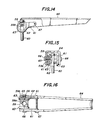
- a lever pivotal member 59 is formed with a vertical bolt passing aperture 59a and on both sides with short shafts 59b centrally formed with screw threaded apertures 59c.
- a bolt 60 is inserted through the aperture 59a and an aperture 48a of an upper cover 48 of the upper center tube 16 into the tube 16 and is threadedly engaged in the connecting nut 58 to be connected to the bolt 56.
- an eccentric cam 42 formed integrally with an arm 61 and a ring 63 rotatably in a manner an outer periphery of the ring 63 being in contact with an upper surface of the upper cover 48.
- a lever 64 having an inverted V-shaped cross-section is formed in its enlarged end with apertures 64a into which bushings 64 are fitted.
- Each a set screw 66 is inserted through the bushing 65 into the threaded aperture 59c of the short shaft 59b so as to be threadedly engaged therewith.
- a set screw 67 extends through apertures 64b formed in the lever 64 and apertures 61 a formed in the respective arms 61 to connected the arms 61 to the lever 64.
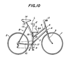
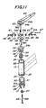
- Figs. 10 and 12 illustrate the lever 64 which has been moved into the front direction or in a horizontal position wherein the front and rear halves A and B of the frame are fixed in a straight or aligned condition.
- the connecting bolts 60 and 56 have been raised through rings 63 by an action of the eccentric cams 62, so that the upper and lower center tubes 16 and 17 have been moved toward each other against the force of the spring 55 to be urged against the center tube 15, respectively.
- the urging force against the center tube 15 is determined by a reaction force resulting from the dish-shaped springs 57. In order to adjust the urging force, therefore, an overall length of the bolts 60 and 56 is previously adjusted into a suitable length.
- the suitable urging force acts between the upper and lower center tubes 16 and 17 respectively and the center tube 15, so that the continuous V-shaped teeth 24 are completely engaged with each other so as to permit the front and rear halves A and B of the frame to be securely fixed to each other.
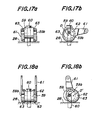
- a center O of each the eccentric cam 62 should be set in a position somewhat beyond a lower dead point (or the position slightly shifted to the left).
- the lever 64 When it is desired to fold the bicycle, the lever 64 is raised from the horizontal position shown in Figs. 10 and 12 in a direction shown by an arrow D.
- the arms 61 fixed to the lever by the screws 47 are also rotated from the position shown in Fig. 17bto a position shown in Fig. 18b.
- the eccentric cams 62 respectively integral with the arms 61 are rotated about the shafts 59b from the position shown in Fig. 17b to the position shown in Fig. 18b, so that the center 0 of each the eccentric cam 62 moves to the position O' shown in Fig. 18b.
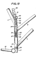
- the upper center tube 16 which has been urged through the upper cover 48 against the ring 63, rises relatively to the center tube 15 with the aid of the coil spring 55 and the lower center tube 17 lowers relatively to the center tube 15 with the aid of the coil spring 55 to release the engagement of the V-shaped teeth 24 as shown in Fig. 13.
- the front half A is rotated about the center line 1 in the direction shown by the arrow E in Fig. 10 to fold the bicycle frame.
- the lever 64 By rotating the lever 64 to the horizontal locking position under this condition, the folded front and rear halves are fixed to each other.
- the rings 63 are slidably fitted on the outer circumferences of the eccentric cams 62, so that outer circumferences of the rings 63 are substantially in rolling contact with the upper surface of the upper cover 48 and inner circumferences of the rings 63 slide on the outer circumferences of the eccentric cams 62, with the result that the resistance in cam action becomes small and frictional wear at contacting members greatly decreases, thereby ensuring smooth operation of the lever and improvement of the device's durability.
- dish-shaped springs 57 are interposed between the head of the bolt 56 and the intermediate disc 51, so that the urging forces between the V-shaped teeth 24 in the fixed condition of the halves are obtained by the strong reaction of the dish-shaped springs 57 to ensure the fixation between the front and rear halves A and B.
- the bolt 56 is formed in its one side with a flat surface so as to be restrained against rotation relatively to the intermediate disc 51 and the bolts 56 and 60 are connected with each other through the connecting nut 58, thereby easily adjusting the overall length of the bolts by rotating the bolt 60. Furthermore, such an adjustment of the bolt length can simultaneously adjust the above fixation force, so that the adjustment as a whole can be easily effected.
- the lever 64 is not shown to include any locking means for clarity. It is very dangerous for a cyclist, if the lever is accidentally moved in the direction as shown by the arrow D so as to release the fixation between the front and rear halves A and B of the bicycle frame when the bicycle is running in the condition as shown in Fig. 10.
- Figs. 19-23 illustrate a further embodiment of the invention comprising locking means for the lever 64 to prevent the release of the fixation between the front and rear halves, wherein like members have been designated by the same reference numerals as in the previous embodiments.
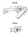
- An upper front tube 6 is provided with an anchoring member 70 in the form of a hook including a round head 70a and a downward directing jaw 70b at a location adjacent to a front end of the lever 64 under the fixing position.
- the lever 64 has of course cams and serves to fix or release continuous V-shaped teeth 24 in opposition to each other at relative rotative portions of a center tube 15 and upper and lower center tubes 16 and 17.
- the lever 64 is formed with a rectangular opening 64c in its upper surface near its front end and with apertures 64d in side walls.
- a lock member 71 is integrally formed so as to have a protrusion 71a extending through the 64c and at its mid portion an opening 71b extending in an axial direction of the lever 64 in assembled condition and adapted to receive and engage the jaw 70b of the anchoring member 70.
- the lock member 71 is further formed with apertures 71c passing through sidewalls of the opening 71 b.
- a reference numeral 71 b denotes a bottom of the opening 71 b.
- a lower end 71 d of the lock member 71 is so curved that the lock member 71 is pivotally moved in a clockwise direction as viewed in Fig. 20 when the lower end 71d d engages the round head 70a of the lock member 71.
- the lock member 71 is formed with a projection 71e serving as a stopper.
- the lock member 71 is inserted in the front end portion of the lever 64 with the protrusion 71a of the lock member 71 extending through the rectangular opening 64c of the lever 64.
- a set screw 72 passes through the apertures 64d of the lever 64, the apertures 71c of the lock member 71 and a coil spring 73 located in the opening 71 b of the lock member 71 so that the lock member 71 is supported by lever 64 pivotally movably relative thereto and urged against the anchoring member 70 into an engagement therewith by the action of the coil spring 73.
- one end 73a of the coil spring 73 engages an inner surface of the lever 64 and the other end 73b of the coil spring 73 engages the lock member 71 so as to normally pivotally urge the lock member 71 as shown by an arrow F in Fig. 20.
- the protrusion 71a a of the lock member 71 is urged inwardly of the lever 64 by a fingertip so as to rotate against the action of the coil spring 73 in a clockwise direction as viewed in Fig. 22 to disengage the lock member 71 from the anchoring member 70. Thereafter the lever 64 is raised in the direction shown by an arrow I in Fig. 22.
- the locking means constructed as above described has the following advantages.
- the locking means can be operated only by moving the lever downward in the front direction.
- the locked lever is not released unless the lock member of the locking means is actuated, so that there is no risk of releasing the fixation of the foldable bicycle by accidentally releasing the lever in running.
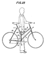
- the locking means is not released unless the protrusion of the lock member is pushed, so that a cyclist can carry the bicycle in his hand gripping the locked lever as shown in Fig. 23.
- the lever also serves as a handle for carrying the bicycle.
- the upper and lower center tubes 16 and 17 should be somewhat moved upward and downward, respectively, releative to the center tube 15 so that the rear half B of the frame should be somewhat deformed from the position shown in solid lines to the position shown in phantom lines in Fig. 24. If the seat stays 12 are completely fixed at their ends to the other frame members, therefore, the rear half B of the frame cannot be deformed as shown in the phantom lines in Fig. 24.
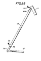
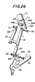
- FIG. 25-28 A next embodiment shown in Figs. 25-28 enables a foldable bicycle to be folded without any immoderate compulsion, wherein like components have been designated by the same reference numerals as in the above embodiments.
- a hollow cylindrical body 69 having a boltpassing aperture 69b in its axial direction is formed in its ends with reduced outer diameter portions 69a to form shoulders.
- the hollow cylindrical body 69 is fixed by welding to a rear surface of a seat tube 11 integral with an upper center tube 16 in the proximity of an upper end of the seat tube 11.
- Seat stays 12 are formed in their upper ends with apertures 12a into which the reduced outer diameter portions 69a of the hollow cylindrical body 69.
- a bolt 70 extends through the apertures 12a of the seat stays 12 and the boltpassing aperture 69b of the hollow cylindrical body 69 and an extending screw threaded end of the bolt 70 is threadedly engaged with a nut 71 so that the upper ends of the seat stays 12 are pivotally secured to the seat pillar 13.
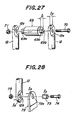
- an extending length I, of the reduced outer diameter portions 69a is preferably slightly longer than a thickness 1 2 of the upper ends of the seat stays 12 as shown in Fig. 27.
- each the seat stay 12 is formed in its lower end with an aperture 12b.
- Each a chain stay 10 is provided at its rear end with a rear claw member 72 integrally fixed thereto.
- Each the rear claw member 72 is formed in its upper end with an aperture 72a corresponding to the aperture 12b of the seat stay 12.
- a collar 73 is inserted into the apertures 72a of the rear claw members 72 and apertures 12b of the seat stays 12.
- a bolt 74 is inserted into the collar 73 and its extending screw threaded end is threadedly engaged with a nut 75 so that the lower ends of the seat stays 12 are . pivotally secured to the rear claw members 72 integral with the chain stays 10.
- a length 1 3 of the collar 73 is preferably slightly longer than a sum of a thickness 1 4 of the upper end of the rear claw member 72 and a thickness 1 5 of the lower end of the seat stay 12, that is, 1 3 >1 4 +1, as shown in Fig. 28. In this manner, when the bolt 74 and nut 75 are tightened, the pivotal movement of the seat stays 12 and the rear claw members 72 is not obstructed.
- the seat stays 12 are not completely fixed to the other frame members so that a foldable bicycle frame can be folded and extended without any compulsion.
- the seat stays are detachable and thus superior in exchangeability, easy to repair and capable of being coated with a different paint from that of other frames. Furthermore, as the seat stays can be simply removed from the rear claw members, a driving belt or chain can be extended in an endless or hoop condition about sprockets.
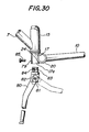
- Figs. 29 and 30 illustrate a further embodiment of a bicycle having a support bar or stay rod for preventing it from falling down when not used.
- a lower center tube 17 opens at its lower end at 17a and is formed in its sidewall with a boltpassing aperture 79.
- a bracket 82 for pivotally supporting a support rod 80 by means of a shaft is provided on its upper end with a shaft portion 83 adapted to be fitted in the opening 17a of the lower center tube 17 and formed in its side of the shaft portion 83 with a screw-threaded aperture 84.
- a bolt 85 is screwed through the aperture 79 into the screw-threaded aperture 84 to secure the support bar to the bicycle frame.
- Fig. 29 illustrates a bicycle having the support bar 80 in the above manner, which is shown in solid lines in an upright position when the bicycle is standing still and in phantom lines in a horizontal position when the bicycle is running.
- the support bar 80 can be securely fixed to the bicycle frame only by inserting the shaft portion 83 into the opening 17a of the lower center tube 17 and screwing the bolt 85 through the aperture 79 into the screw-threaded aperture 84. Moreover, a removal of the support bar 80 from the bicycle frame can be easily effected by removing the bolt 85 and the shaft portion 83. Accordingly, the support bar 80 can be very easily attached to and removed from the bicycle frame.
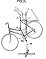
- bicycles according to this embodiment can be simply and neatly exhibited by fitting the openings 17a of lower center tubes 17 onto ends 86a and 86b of branch tubes of a stand 86 for exhibition after removal of support rods 80 as shown in Fig. 31.
- This embodiment has the following advantages.
Landscapes
- Engineering & Computer Science (AREA)
- Mechanical Engineering (AREA)
- Motorcycle And Bicycle Frame (AREA)
Claims (17)
Applications Claiming Priority (12)
| Application Number | Priority Date | Filing Date | Title |
|---|---|---|---|
| JP103542/83 | 1983-06-11 | ||
| JP10354283A JPS59230878A (ja) | 1983-06-11 | 1983-06-11 | 折り畳み自転車フレ−ム |
| JP9115883U JPS59196385U (ja) | 1983-06-16 | 1983-06-16 | 折り畳み自転車のスタンド |
| JP91158/83 | 1983-06-16 | ||
| JP9115983U JPS59196390U (ja) | 1983-06-16 | 1983-06-16 | 折り畳み自転車フレ−ムの位置決め装置 |
| JP91159/83 | 1983-06-16 | ||
| JP9782183U JPS605986U (ja) | 1983-06-27 | 1983-06-27 | 折り畳み自転車フレ−ムの固定装置 |
| JP97821/83 | 1983-06-27 | ||
| JP101005/83 | 1983-07-01 | ||
| JP10100583U JPS609782U (ja) | 1983-07-01 | 1983-07-01 | 折り畳み自転車のバツクホ−ク |
| JP103394/83 | 1983-07-05 | ||
| JP10339483U JPS6011289U (ja) | 1983-07-05 | 1983-07-05 | 折り畳み自転車フレ−ムの固定装置用レバ−のロツク装置 |
Publications (3)
| Publication Number | Publication Date |
|---|---|
| EP0129164A2 EP0129164A2 (fr) | 1984-12-27 |
| EP0129164A3 EP0129164A3 (en) | 1985-10-30 |
| EP0129164B1 true EP0129164B1 (fr) | 1988-09-07 |
Family
ID=27551836
Family Applications (1)
| Application Number | Title | Priority Date | Filing Date |
|---|---|---|---|
| EP84106578A Expired EP0129164B1 (fr) | 1983-06-11 | 1984-06-08 | Châssis de cycle pliable |
Country Status (3)
| Country | Link |
|---|---|
| US (1) | US4579360A (fr) |
| EP (1) | EP0129164B1 (fr) |
| DE (1) | DE3473862D1 (fr) |
Families Citing this family (35)
| Publication number | Priority date | Publication date | Assignee | Title |
|---|---|---|---|---|
| US4900047A (en) * | 1988-10-28 | 1990-02-13 | Harry Montague | Foldable bicycle |
| US5222751A (en) * | 1991-01-22 | 1993-06-29 | Chen Robert W P | Foldable bicycle frame |
| DE4207771C2 (de) * | 1992-03-11 | 1996-05-15 | Robert W P Chen | Faltbares Fahrrad |
| ES2108823T3 (es) * | 1993-07-14 | 1998-01-01 | Robert W P Chen | Cuadro de bicicleta plegable. |
| US5419573A (en) * | 1994-04-08 | 1995-05-30 | Kao; Fu-Hsiung | Folding bicycle |
| DE59604553D1 (de) * | 1995-09-12 | 2000-04-06 | Denys F Hackert | Klapprad |
| WO1997037886A1 (fr) | 1996-04-08 | 1997-10-16 | Montague Harry D | Cadre de bicyclette pliable |
| US6406047B1 (en) * | 1997-05-01 | 2002-06-18 | Thomas Kidder Sawyer, Jr. | Tommy two drive bicycle |
| US5975551A (en) * | 1997-07-18 | 1999-11-02 | Montague Corporation | Folding frame bicycle |
| US5836602A (en) * | 1997-08-12 | 1998-11-17 | Wang; Ping-Tien | Collapsible bicycle |
| NL1009314C2 (nl) * | 1998-06-04 | 1999-12-07 | Urban Solutions B V | Rijwiel voorzien van trapaandrijving, alsmede trapaandrijving. |
| AUPP477698A0 (en) * | 1998-07-21 | 1998-08-13 | Ep Manufacturing Bhd | Improvements in bicycle construction |
| DE50311119D1 (de) * | 2002-04-09 | 2009-03-12 | Engelbert Rolli | Verfahren für ein gezieltes training und trainingsgerät |
| US6984194B2 (en) * | 2003-03-10 | 2006-01-10 | New Art City Industrial Co., Ltd. | Foldable bike |
| WO2011063059A1 (fr) * | 2009-11-18 | 2011-05-26 | Rapiscan Systems, Inc. | Système et procédés à base de rayons x pour rechercher, dans les chaussures d'une personne, des menaces affectant la sécurité aéronautique |
| US8123243B2 (en) * | 2009-12-18 | 2012-02-28 | Ho William M | Foldable bicycle |
| US8141893B2 (en) * | 2010-01-11 | 2012-03-27 | Lin Wen Teng | Folding apparatus for a bicycle frame |
| TW201136794A (en) * | 2010-04-20 | 2011-11-01 | Univ Nat Formosa | Folding bicycle containing telescopic rod |
| USD636298S1 (en) * | 2010-09-07 | 2011-04-19 | Tai-Her Yang | Bicycle |
| FR2969980B1 (fr) * | 2010-12-31 | 2013-11-22 | Decathlon Sa | Bicyclette pliable |
| JP3175053U (ja) * | 2011-02-18 | 2012-04-19 | 明宏 鄭 | 大小の車輪径を具有する折りたたみ自転車 |
| CN104884133B (zh) | 2013-03-14 | 2018-02-23 | 艾肯运动与健康公司 | 具有飞轮的力量训练设备 |
| US9403047B2 (en) | 2013-12-26 | 2016-08-02 | Icon Health & Fitness, Inc. | Magnetic resistance mechanism in a cable machine |
| US10150529B2 (en) * | 2014-06-06 | 2018-12-11 | Bignay, Inc. | Vertically folding bicycle with locking mechanism |
| CN106470739B (zh) | 2014-06-09 | 2019-06-21 | 爱康保健健身有限公司 | 并入跑步机的缆索系统 |
| US9834275B2 (en) | 2015-07-22 | 2017-12-05 | Montague Corporation | Non-overlapping frame folding bike |
| TWI644702B (zh) | 2015-08-26 | 2018-12-21 | 美商愛康運動與健康公司 | 力量運動機械裝置 |
| US10940360B2 (en) | 2015-08-26 | 2021-03-09 | Icon Health & Fitness, Inc. | Strength exercise mechanisms |
| US10293211B2 (en) | 2016-03-18 | 2019-05-21 | Icon Health & Fitness, Inc. | Coordinated weight selection |
| US10441840B2 (en) | 2016-03-18 | 2019-10-15 | Icon Health & Fitness, Inc. | Collapsible strength exercise machine |
| US10252109B2 (en) | 2016-05-13 | 2019-04-09 | Icon Health & Fitness, Inc. | Weight platform treadmill |
| US10661114B2 (en) | 2016-11-01 | 2020-05-26 | Icon Health & Fitness, Inc. | Body weight lift mechanism on treadmill |
| FR3070453A1 (fr) * | 2017-08-31 | 2019-03-01 | Pierre-Adrien Ducarre | Dispositif de pliage rapide et sans jeu de vehicules a roues |
| CN214451575U (zh) * | 2020-12-30 | 2021-10-22 | 深圳市美大行科技有限公司 | 折叠接头及折叠车架 |
| US12623747B2 (en) * | 2022-07-10 | 2026-05-12 | Bert Vermeulen | Systems and methods for folding and packing a human powerable vehicle |
Family Cites Families (12)
| Publication number | Priority date | Publication date | Assignee | Title |
|---|---|---|---|---|
| US518330A (en) * | 1894-04-17 | Necticut | ||
| US1096504A (en) * | 1913-06-17 | 1914-05-12 | David Grossman | Folding bicycle. |
| US1584568A (en) * | 1922-02-17 | 1926-05-11 | Clark Charles Haskell | Bicycle and the like |
| FR973308A (fr) | 1941-08-30 | 1951-02-09 | Vélocipède portatif | |
| FR977665A (fr) * | 1942-10-06 | 1951-04-04 | Bicyclette | |
| FR893184A (fr) * | 1942-12-12 | 1944-06-01 | Bicyclette portative | |
| US2394494A (en) * | 1944-03-13 | 1946-02-05 | Frank W Schwinn | Folding bicycle frame |
| US3512816A (en) * | 1967-09-06 | 1970-05-19 | Katano Jitensha Kk | Means for connecting front and rear portions of a foldable bicycle |
| AU503065B2 (en) * | 1975-06-02 | 1979-08-23 | G. N Klimpsch | Foldable bicycle |
| US3980320A (en) * | 1975-08-27 | 1976-09-14 | Marchello John L | Bicycle support stand |
| US4022485A (en) * | 1976-04-05 | 1977-05-10 | Cox Elward Leroy | Collapsible bicycle |
| US4417745A (en) * | 1981-03-16 | 1983-11-29 | Shomo Robert D | Folding bicycle |
-
1984
- 1984-06-05 US US06/617,391 patent/US4579360A/en not_active Expired - Lifetime
- 1984-06-08 DE DE8484106578T patent/DE3473862D1/de not_active Expired
- 1984-06-08 EP EP84106578A patent/EP0129164B1/fr not_active Expired
Also Published As
| Publication number | Publication date |
|---|---|
| EP0129164A3 (en) | 1985-10-30 |
| EP0129164A2 (fr) | 1984-12-27 |
| DE3473862D1 (en) | 1988-10-13 |
| US4579360A (en) | 1986-04-01 |
Similar Documents
| Publication | Publication Date | Title |
|---|---|---|
| US4579360A (en) | Foldable bicycle frame | |
| US7712614B2 (en) | Bicycle frame clamp adaptor | |
| US4417745A (en) | Folding bicycle | |
| US4182522A (en) | Folding bicycles | |
| EP0092811B1 (fr) | Guidon réglable pour cycle | |
| EP1625068B1 (fr) | Bicyclette pliable | |
| EP0142321B1 (fr) | Bicyclette pliable | |
| US7992889B2 (en) | Convertible stroller-cycle | |
| US6497426B2 (en) | Convertible bicycle | |
| US8720927B2 (en) | Collapsible recumbent tricycle | |
| EP1902936B1 (fr) | Dérailleur arrière pour bicyclette | |
| US4296940A (en) | Folding bicycle | |
| US6712375B2 (en) | Stretchable bicycle | |
| US20090146391A1 (en) | Folding Bicycle Constructed from Plate Frame Elements | |
| EP0058522A1 (fr) | Véhicule pliable et portablecomportant un guidon pliable | |
| US8556284B2 (en) | Sectional bicycle | |
| US20020139217A1 (en) | Adjustable and foldable stem and bearings for wheeled vehicles | |
| EP0996564A1 (fr) | Cadre pliant de bicyclette | |
| US4022485A (en) | Collapsible bicycle | |
| JPS582103B2 (ja) | ジテンシヤ | |
| TW202500435A (zh) | 伸縮自行車支架總成 | |
| WO1992002402A1 (fr) | Bicyclette pliable | |
| US5947500A (en) | Cycle frame assembly | |
| US5997023A (en) | Retractable foot peg for self propelled, multiwheeled vehicles | |
| EP1352821B1 (fr) | Bicyclette à longueur variable |
Legal Events
| Date | Code | Title | Description |
|---|---|---|---|
| PUAI | Public reference made under article 153(3) epc to a published international application that has entered the european phase |
Free format text: ORIGINAL CODE: 0009012 |
|
| AK | Designated contracting states |
Designated state(s): DE FR GB IT NL |
|
| PUAL | Search report despatched |
Free format text: ORIGINAL CODE: 0009013 |
|
| AK | Designated contracting states |
Designated state(s): DE FR GB IT NL |
|
| 17P | Request for examination filed |
Effective date: 19851212 |
|
| 17Q | First examination report despatched |
Effective date: 19860919 |
|
| GRAA | (expected) grant |
Free format text: ORIGINAL CODE: 0009210 |
|
| ITF | It: translation for a ep patent filed | ||
| AK | Designated contracting states |
Kind code of ref document: B1 Designated state(s): DE FR GB IT NL |
|
| REF | Corresponds to: |
Ref document number: 3473862 Country of ref document: DE Date of ref document: 19881013 |
|
| ET | Fr: translation filed | ||
| PLBE | No opposition filed within time limit |
Free format text: ORIGINAL CODE: 0009261 |
|
| STAA | Information on the status of an ep patent application or granted ep patent |
Free format text: STATUS: NO OPPOSITION FILED WITHIN TIME LIMIT |
|
| 26N | No opposition filed | ||
| ITTA | It: last paid annual fee | ||
| PGFP | Annual fee paid to national office [announced via postgrant information from national office to epo] |
Ref country code: NL Payment date: 19940630 Year of fee payment: 11 |
|
| PGFP | Annual fee paid to national office [announced via postgrant information from national office to epo] |
Ref country code: GB Payment date: 19950523 Year of fee payment: 12 |
|
| PG25 | Lapsed in a contracting state [announced via postgrant information from national office to epo] |
Ref country code: NL Effective date: 19960101 |
|
| NLV4 | Nl: lapsed or anulled due to non-payment of the annual fee |
Effective date: 19960101 |
|
| PG25 | Lapsed in a contracting state [announced via postgrant information from national office to epo] |
Ref country code: GB Effective date: 19960608 |
|
| GBPC | Gb: european patent ceased through non-payment of renewal fee |
Effective date: 19960608 |
|
| PGFP | Annual fee paid to national office [announced via postgrant information from national office to epo] |
Ref country code: FR Payment date: 19970619 Year of fee payment: 14 |
|
| PG25 | Lapsed in a contracting state [announced via postgrant information from national office to epo] |
Ref country code: FR Free format text: LAPSE BECAUSE OF NON-PAYMENT OF DUE FEES Effective date: 19990226 |
|
| REG | Reference to a national code |
Ref country code: FR Ref legal event code: ST |
|
| PGFP | Annual fee paid to national office [announced via postgrant information from national office to epo] |
Ref country code: DE Payment date: 20010628 Year of fee payment: 18 |
|
| PG25 | Lapsed in a contracting state [announced via postgrant information from national office to epo] |
Ref country code: DE Free format text: LAPSE BECAUSE OF NON-PAYMENT OF DUE FEES Effective date: 20030101 |