EP0129166A2 - Boîte dynamométrique - Google Patents
Boîte dynamométrique Download PDFInfo
- Publication number
- EP0129166A2 EP0129166A2 EP84106583A EP84106583A EP0129166A2 EP 0129166 A2 EP0129166 A2 EP 0129166A2 EP 84106583 A EP84106583 A EP 84106583A EP 84106583 A EP84106583 A EP 84106583A EP 0129166 A2 EP0129166 A2 EP 0129166A2
- Authority
- EP
- European Patent Office
- Prior art keywords
- strain gauge
- gauge resistors
- load cell
- resistors
- stress
- Prior art date
- Legal status (The legal status is an assumption and is not a legal conclusion. Google has not performed a legal analysis and makes no representation as to the accuracy of the status listed.)
- Granted
Links
Images
Classifications
-
- G—PHYSICS
- G01—MEASURING; TESTING
- G01L—MEASURING FORCE, STRESS, TORQUE, WORK, MECHANICAL POWER, MECHANICAL EFFICIENCY, OR FLUID PRESSURE
- G01L1/00—Measuring force or stress, in general
- G01L1/20—Measuring force or stress, in general by measuring variations in ohmic resistance of solid materials or of electrically-conductive fluids; by making use of electrokinetic cells, i.e. liquid-containing cells wherein an electrical potential is produced or varied upon the application of stress
- G01L1/22—Measuring force or stress, in general by measuring variations in ohmic resistance of solid materials or of electrically-conductive fluids; by making use of electrokinetic cells, i.e. liquid-containing cells wherein an electrical potential is produced or varied upon the application of stress using resistance strain gauges
- G01L1/2287—Measuring force or stress, in general by measuring variations in ohmic resistance of solid materials or of electrically-conductive fluids; by making use of electrokinetic cells, i.e. liquid-containing cells wherein an electrical potential is produced or varied upon the application of stress using resistance strain gauges constructional details of the strain gauges
-
- G—PHYSICS
- G01—MEASURING; TESTING
- G01L—MEASURING FORCE, STRESS, TORQUE, WORK, MECHANICAL POWER, MECHANICAL EFFICIENCY, OR FLUID PRESSURE
- G01L1/00—Measuring force or stress, in general
- G01L1/20—Measuring force or stress, in general by measuring variations in ohmic resistance of solid materials or of electrically-conductive fluids; by making use of electrokinetic cells, i.e. liquid-containing cells wherein an electrical potential is produced or varied upon the application of stress
- G01L1/22—Measuring force or stress, in general by measuring variations in ohmic resistance of solid materials or of electrically-conductive fluids; by making use of electrokinetic cells, i.e. liquid-containing cells wherein an electrical potential is produced or varied upon the application of stress using resistance strain gauges
- G01L1/2206—Special supports with preselected places to mount the resistance strain gauges; Mounting of supports
- G01L1/2243—Special supports with preselected places to mount the resistance strain gauges; Mounting of supports the supports being parallelogram-shaped
-
- G—PHYSICS
- G01—MEASURING; TESTING
- G01L—MEASURING FORCE, STRESS, TORQUE, WORK, MECHANICAL POWER, MECHANICAL EFFICIENCY, OR FLUID PRESSURE
- G01L1/00—Measuring force or stress, in general
- G01L1/20—Measuring force or stress, in general by measuring variations in ohmic resistance of solid materials or of electrically-conductive fluids; by making use of electrokinetic cells, i.e. liquid-containing cells wherein an electrical potential is produced or varied upon the application of stress
- G01L1/22—Measuring force or stress, in general by measuring variations in ohmic resistance of solid materials or of electrically-conductive fluids; by making use of electrokinetic cells, i.e. liquid-containing cells wherein an electrical potential is produced or varied upon the application of stress using resistance strain gauges
- G01L1/225—Measuring circuits therefor
- G01L1/2262—Measuring circuits therefor involving simple electrical bridges
Definitions
- the present invention relates to a load cell having strain gauge resistors and conductive layers formed by a thin film technique.
- a load cell having strain gauge resistors formed through insulation layers on a beam body having a strain generating section and a conductive pattern for forming a bridge circuit by coupling these strain gauge resistors is known.
- these strain gauge resistors and the conductive pattern are formed by depositing, sputtering, or plating.
- the conductive pattern is formed thick.
- resistors while varying in age. In this manner, the resistance values of the strain gauge resistors alter, and bridge balance or span (the output voltage of the load cell) resultantly varies in age, thereby causing the performance of the load cell to be deteriorated.
- the conductive pattern is composed of a conductive layer selectively formed on a resistive layer for forming strain gauge resistors.
- the resistive layer under this conductive layer is contracted or expanded in response to the contraction or expansion of the conductive layer due to the difference of thermal expansion between the resistive layer and the conductive layer.
- a stress generated by this contraction or expansion is transmitted through the insulation layer to the strain gauge resistors, thereby altering the resistance value of the strain gauge resistors to cause the bridge. balance or span to be varied.
- a load cell comprising a beam body having a strain generating section, a plurality of strain gauge resistors formed through an insulation layer on the beam body, a conductive pattern for forming a bridge circuit by coupling these strain gauge resistors, a plurality of compensation resistance sections for compensating the bridge balance and span of the bridge circuit, wherein a section except the section coupled to the strain gauge resistors of the conductive pattern is disposed at a position sufficiently isolated from these strain gauge resistors.
- the aging stress and thermal stress due to this conductive pattern are not substantially transmitted to the strain gauge resistors, but absorbed by the insulation layer so as not to affect the influence thereof to the bridge balance and span.
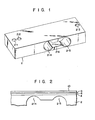
- Fig. 1 shows a beam body 2 used for forming a load cell according an embodiment of the present invention.
- This beam body 2 is obtained, for example, by cutting a stainless steel (SUS 630) or duralumin (A2014, A2024 or A2218).
- the beam body 2 has two through holes 2-1 and 2-2 formed to receive clamping bolts at a stationary end, and a through hole 2-3 formed to receive a supporting clamp (not shown) for supporting a weighing tray at a movable end.
- the beam body 2 has two lateral through holes 2-4 and 2-5 formed to extend laterally, and a coupling hole for coupling the holes 2-4 and 2-5. Those portions of the beam body 2 which correspond to the top portions of the holes 2-4 and 2-5 form a strain generating section.
- an insulation film 4 having, for example, a thickness of 4 pm is first formed of an insulation material formed of an inorganic material such as a Si0 2 or an organic material such as polyimide resin on the beam body 2 as shown in Fig. 2. Then, a resistive layer 6 formed, for example, of a material such as NiCrSi which is used for forming strain gauge resistors and bridge balance correcting resistor and is hardly affected in electric characteristics by the temperature change is formed by sputtering, depositing in a thickness, for example, of 0.1 pm, on the film 4.
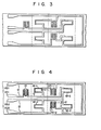
- a laminate of layers 6, 8 and 10 is selectively removed by photoetching, to form a pattern which includes the regions of strain gauge resistors, bridge balance correcting resistor, span temperature compensating resistor, bridge balance temperature compensating resistor, terminal sections and interconnecting sections as shown in Fig. 3.
- the conductive layer 10 in the regions of the strain gauge resistors, bridge balance correcting resistor, span temperature compensating resistor and bridge balance temperature compensating resistor is removed by etching.
- the span temperature compensating resistor 14 and the bridge balance temperature compensating resistors 16-1 and 16-2 are formed of the resistive layer 8 thus exposed, and a power source terminal VE1 and VE2, output terminals VOl and V02, and interconnection sections 12 are formed of the remaining conductive layer 10.
- the resistive layer 8 in the regions of the strain gauge resistors and the bridge balance correcting resistor is subsequently removed by etching, and the resistive layer 6 is exposed.
- Strain gauge resistors 18-1 to 18-4 and bridge balance compensating resistors 20-1 and 20-2 are formed of the resistive layer 6 thus exposed.
- the resistive layer 6 is formed in sufficiently reduced thickness such as, for example, 0.1 pm, and in order to sufficiently reduce the resistance value of the . interconnection section 12, the conductive layer 10 is formed in relatively large thickness of, for example, 2 ⁇ m .
- the span temperature compensating resistor 14, bridge balance temperature compensating resistors 16-1 and 16-2,.and bridge balance correcting resistors 20-1 and 20-2 are disposed at the position where the beam body 2 is not substantially deformed when a load is applied to the load cell. Therefore, when a load is applied to the load cell, an expansion stress is applied to the strain gauge resistors 18-1 and 18-4, and a compression stress is applied to the strain gauge resistors 18-2 and 18-3, but no stress is applied to the other resistors.
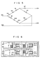
- Fig. 5 shows an equivalent circuit of the load cell thus obtained.
- resistors Rl to R4 respectively correspond to the strain gauge resistors 18-1 to 18-4
- resistors RX1 and RX2 respectively correspond to the bridge balance correcting resistors 20-1 and 30-2
- resistors RY1 and RY2 respectively correspond to the bridge balance temperature compensating resistors 16-1 and 16-2
- a resistor RZ corresponds to the span temperature compensating resistor.
- the interconnection sections 12 are formed separately from these strain gauge resistors 18-1 to 18-4 to surround the strain gauge resistors 18-1 to 18-4, and the influence of the aging stress and thermal stress in these interconnection sections 12 to the resistances of the strain gauge resistors 18-1 to 18-4 is suppressed to the minimum value.
- these interconnection sections 12 include the conductive layer formed to longitudinally extend on both ends of the beam body, and the strain gauge resistors 18-1 to 18-4.are respectively disposed at the equal interval from the corresponding conductive layers.
- Fig. 6 shows a load cell according another embodiment of the present invention.
- This load cell is constructed substantially in the same manner as that shown in Fig. 4 except that having stress generating sections 22-1 to 22-4 formed similarly to the interconnection sections 12 which extend in parallel with each other in the vicinity of strain gauge resistors 18-1 to 18-4.
- Each of the stress generating sections is formed of a laminate of resistive layers and conductive layer formed of the same material as the resistive layers 6 and 8 and conductive layer 10 on an insulation layer 4.
- the dimensions of the stress generating sections 22-1 and 22-2 are empirically determined so that the aging stresses and thermal stress applied by the stress generating sections to the strain gauge resistors 18-1 to 18-4 are proportional to one another, e.g., these stress generating sections 22-1 are formed substantially the same as those of the stress generating sections 22-2, and the distance between the stress generating sections 22-1 and the strain gauge resistor 18-1 is set substantially equal to the distance between the stress generating sections 22-2 and the strain gauge resistor 18-2.
- the sizes of these stress generating sections 22-3 and 22-4 are set equal so that the aging and thermal stresses applied by the stress generating sections 22-3 and 22-4 to the strain gauge resistors 18-3 and 18-4 are proportional to one another.
- the aging and thermal stresses of the stress generating sections 22-1 to 22-4 applied to the strain gauge resistors 18-1 to 18-4 are much larger than those of the interconnection sections 12 applied to the strain gauge resistors 18-1 to 18-4, and the bridge balance can be accordingly maintained substantially constant irrespective of the aging and thermal stresses.
- the bridge balance can also be maintained by respectively setting the dimensions of the stress generating sections 22-1 and 22-4 substantially equal to those of the stress generating sections 22-3 and 22-2, equalizing the stresses of the stress generating sections 22-1 and 22-3 with respect to the strain gauge resistors 18-1 and 18-3, and equalizing the stresses of the stress generating sections 22-2 and 22-4 with respect to the strain gauge resistors 18-2 and 18-4.
Landscapes
- Physics & Mathematics (AREA)
- General Physics & Mathematics (AREA)
- Measurement Of Force In General (AREA)
Applications Claiming Priority (2)
| Application Number | Priority Date | Filing Date | Title |
|---|---|---|---|
| JP105497/83 | 1983-06-13 | ||
| JP58105497A JPS59230131A (ja) | 1983-06-13 | 1983-06-13 | ロ−ドセル |
Publications (3)
| Publication Number | Publication Date |
|---|---|
| EP0129166A2 true EP0129166A2 (fr) | 1984-12-27 |
| EP0129166A3 EP0129166A3 (en) | 1987-05-13 |
| EP0129166B1 EP0129166B1 (fr) | 1990-09-12 |
Family
ID=14409232
Family Applications (1)
| Application Number | Title | Priority Date | Filing Date |
|---|---|---|---|
| EP84106583A Expired EP0129166B1 (fr) | 1983-06-13 | 1984-06-08 | Boîte dynamométrique |
Country Status (4)
| Country | Link |
|---|---|
| US (1) | US4628296A (fr) |
| EP (1) | EP0129166B1 (fr) |
| JP (1) | JPS59230131A (fr) |
| DE (1) | DE3483176D1 (fr) |
Cited By (2)
| Publication number | Priority date | Publication date | Assignee | Title |
|---|---|---|---|---|
| DE102016217585B3 (de) * | 2016-09-15 | 2017-08-03 | Schaeffler Technologies AG & Co. KG | Dehnungsmesstreifen sowie Verfahren zur Herstellung eines Dehnungsmessstreifens |
| CN114777970A (zh) * | 2022-05-23 | 2022-07-22 | 电子科技大学 | 高刚度测力刀柄上基于柔性电路板的薄膜应变计电桥电路 |
Families Citing this family (21)
| Publication number | Priority date | Publication date | Assignee | Title |
|---|---|---|---|---|
| US4777826A (en) * | 1985-06-20 | 1988-10-18 | Rosemount Inc. | Twin film strain gauge system |
| JPS6210628U (fr) * | 1985-07-04 | 1987-01-22 | ||
| JPH0711461B2 (ja) * | 1986-06-13 | 1995-02-08 | 株式会社日本自動車部品総合研究所 | 圧力検出器 |
| EP0251563A3 (fr) * | 1986-06-17 | 1991-01-09 | Tokyo Electric Co. Ltd. | Dispositif de conversion photoélectrique |
| JP2666209B2 (ja) * | 1986-09-22 | 1997-10-22 | 株式会社テック | ロードセルの製造方法 |
| FR2643148B1 (fr) * | 1989-02-15 | 1991-12-06 | Schlumberger Ind Sa | Capteur de pression du type semiconducteur sur isolant |
| DE19643868A1 (de) * | 1996-10-30 | 1998-05-07 | Rene Baltus | Wägezellenanordnung |
| US6700473B2 (en) * | 2000-02-14 | 2004-03-02 | Kulite Semiconductor Products, Inc. | Pressure transducer employing on-chip resistor compensation |
| JP2001343294A (ja) * | 2000-05-31 | 2001-12-14 | Ishida Co Ltd | ロードセル及び秤 |
| US6688185B2 (en) * | 2001-08-20 | 2004-02-10 | Autoliv Asp, Inc. | System and method for microstrain measurement |
| JP2003214962A (ja) * | 2002-01-18 | 2003-07-30 | Toyoda Mach Works Ltd | 荷重センサー |
| US6758098B1 (en) * | 2002-02-20 | 2004-07-06 | The United States Of America As Represented By The Administrator Of The National Aeronautics And Space Administration | Force-measuring clamp |
| US7342185B2 (en) * | 2003-06-10 | 2008-03-11 | The Flintec Group, Ltd. | Compression column load cell with compensation for off center loading errors |
| JP2005233953A (ja) * | 2004-02-17 | 2005-09-02 | Robert Bosch Gmbh | マイクロメカニカル式の高圧センサを製造するための方法及びマクロメカニカル式の圧力センサ |
| US20060185446A1 (en) * | 2005-02-18 | 2006-08-24 | Speckhart Frank H | Printed strain gage for vehicle seats |
| WO2008029648A1 (fr) * | 2006-09-05 | 2008-03-13 | Ishida Co., Ltd. | Module de cellules de charge, contrôleur de poids, et instrument de pesée électronique |
| US8757013B1 (en) * | 2011-07-20 | 2014-06-24 | BG Systems, Inc. | Force transducer with separately mounted calibration resistors |
| US8833176B1 (en) * | 2011-09-04 | 2014-09-16 | Daniel Shapiro | Deadeye for measuring tension in rigging for boats |
| US9557230B2 (en) | 2011-10-21 | 2017-01-31 | Csem Centre Suisse D'electronique Et De Microtechnique Sa—Recherche Et Developpement | SiC high temperature pressure transducer |
| US12553782B2 (en) * | 2022-06-29 | 2026-02-17 | Subaru Corporation | Load cell and output adjustment method of load cell |
| USD1114650S1 (en) * | 2024-09-09 | 2026-02-24 | Paul Nash | Self-charging load cell |
Family Cites Families (13)
| Publication number | Priority date | Publication date | Assignee | Title |
|---|---|---|---|---|
| US2866059A (en) * | 1956-06-01 | 1958-12-23 | Baldwin Lima Hamilton Corp | Slotted type multiple bending beam |
| US3199057A (en) * | 1963-05-03 | 1965-08-03 | Lockheed Aircraft Corp | Load cell transducer |
| US3697918A (en) * | 1971-08-03 | 1972-10-10 | Gen Electric | Silicon diaphragm pressure sensor having improved configuration of integral strain gage elements |
| US4376929A (en) * | 1976-12-27 | 1983-03-15 | Myhre Kjell E | Optimized stress and strain distribution diaphragms |
| US4299130A (en) * | 1979-10-22 | 1981-11-10 | Gould Inc. | Thin film strain gage apparatus with unstrained temperature compensation resistances |
| US4320664A (en) * | 1980-02-25 | 1982-03-23 | Texas Instruments Incorporated | Thermally compensated silicon pressure sensor |
| US4325048A (en) * | 1980-02-29 | 1982-04-13 | Gould Inc. | Deformable flexure element for strain gage transducer and method of manufacture |
| DE3042506C2 (de) * | 1980-11-11 | 1986-10-09 | Gould Inc., Rolling Meadows, Ill. | Dehnungsmeßstreifenwandler |
| EP0053337B1 (fr) * | 1980-11-29 | 1987-05-20 | Tokyo Electric Co., Ltd. | Cellule de mesure de charge et procédé pour sa manufacture |
| JPS57196124A (en) * | 1981-05-27 | 1982-12-02 | Toshiba Corp | Load cell |
| JPS57175233A (en) * | 1981-04-21 | 1982-10-28 | Toshiba Corp | Measuring method of residual stress |
| JPS58142206A (ja) * | 1982-02-18 | 1983-08-24 | Tokyo Electric Co Ltd | 歪センサ |
| US4462018A (en) * | 1982-11-05 | 1984-07-24 | Gulton Industries, Inc. | Semiconductor strain gauge with integral compensation resistors |
-
1983
- 1983-06-13 JP JP58105497A patent/JPS59230131A/ja active Granted
-
1984
- 1984-06-04 US US06/616,964 patent/US4628296A/en not_active Expired - Lifetime
- 1984-06-08 EP EP84106583A patent/EP0129166B1/fr not_active Expired
- 1984-06-08 DE DE8484106583T patent/DE3483176D1/de not_active Expired - Lifetime
Cited By (3)
| Publication number | Priority date | Publication date | Assignee | Title |
|---|---|---|---|---|
| DE102016217585B3 (de) * | 2016-09-15 | 2017-08-03 | Schaeffler Technologies AG & Co. KG | Dehnungsmesstreifen sowie Verfahren zur Herstellung eines Dehnungsmessstreifens |
| US11150073B2 (en) | 2016-09-15 | 2021-10-19 | Schaeffler Technologies AG & Co. KG | Strain gauge having first and second insulation layers and method for producing such a strain gauge |
| CN114777970A (zh) * | 2022-05-23 | 2022-07-22 | 电子科技大学 | 高刚度测力刀柄上基于柔性电路板的薄膜应变计电桥电路 |
Also Published As
| Publication number | Publication date |
|---|---|
| US4628296A (en) | 1986-12-09 |
| JPS59230131A (ja) | 1984-12-24 |
| EP0129166A3 (en) | 1987-05-13 |
| DE3483176D1 (de) | 1990-10-18 |
| JPH0565807B2 (fr) | 1993-09-20 |
| EP0129166B1 (fr) | 1990-09-12 |
Similar Documents
| Publication | Publication Date | Title |
|---|---|---|
| EP0129166A2 (fr) | Boîte dynamométrique | |
| US4747456A (en) | Load cell and temperature correction of the same | |
| US4432247A (en) | Load cell having thin film strain gauges | |
| US4329878A (en) | Bridge circuit formed of two or more resistance strain gauges | |
| EP0702220B2 (fr) | Boíte dynamométrique et dispositif de pesage l'utilisant | |
| US8581687B2 (en) | Four-terminal resistor with four resistors and adjustable temperature coefficient of resistance | |
| EP2459977B1 (fr) | Compensation de circuit dans des transducteurs à base d extensomètres | |
| US4267724A (en) | Strain-gage transducer bridge gages with integral calibration resistors | |
| JP2527779B2 (ja) | 圧力センサ | |
| US4748858A (en) | Strain gage transducer | |
| US5309136A (en) | Electrical circuit such as a Wheatstone bridge with a resistance-adjusting portion | |
| US5039976A (en) | High-precision, high-stability resistor elements | |
| JPH05248925A (ja) | ロードセル、ロードセルの製造方法、計量器及び計量方法 | |
| EP0168149A2 (fr) | Pont de jauges de contrainte | |
| GB2142776A (en) | Strain sensor | |
| JPS5942402A (ja) | 歪センサの製造方法 | |
| US10215651B2 (en) | Trimmable links for selectively setting transducer impedance | |
| US3621435A (en) | Transducer beam with back-to-back related deposited film type strain gages | |
| RU2807002C1 (ru) | Тензорезисторный датчик силы | |
| JPS5942401A (ja) | 歪センサ | |
| JP3802216B2 (ja) | ロードセル及びロードセルの温度補償方法 | |
| KR860000048B1 (ko) | 로오드셀 및 그 제조방법 | |
| JPS63285402A (ja) | ロ−ドセル | |
| JPS63289402A (ja) | ロ−ドセル | |
| JPH11201837A (ja) | ロードセル及びロードセルの温度補償方法 |
Legal Events
| Date | Code | Title | Description |
|---|---|---|---|
| PUAI | Public reference made under article 153(3) epc to a published international application that has entered the european phase |
Free format text: ORIGINAL CODE: 0009012 |
|
| AK | Designated contracting states |
Designated state(s): DE GB |
|
| PUAL | Search report despatched |
Free format text: ORIGINAL CODE: 0009013 |
|
| AK | Designated contracting states |
Kind code of ref document: A3 Designated state(s): DE GB |
|
| 17P | Request for examination filed |
Effective date: 19870902 |
|
| 17Q | First examination report despatched |
Effective date: 19880811 |
|
| GRAA | (expected) grant |
Free format text: ORIGINAL CODE: 0009210 |
|
| AK | Designated contracting states |
Kind code of ref document: B1 Designated state(s): DE GB |
|
| REF | Corresponds to: |
Ref document number: 3483176 Country of ref document: DE Date of ref document: 19901018 |
|
| PLBE | No opposition filed within time limit |
Free format text: ORIGINAL CODE: 0009261 |
|
| STAA | Information on the status of an ep patent application or granted ep patent |
Free format text: STATUS: NO OPPOSITION FILED WITHIN TIME LIMIT |
|
| 26N | No opposition filed | ||
| PGFP | Annual fee paid to national office [announced via postgrant information from national office to epo] |
Ref country code: DE Payment date: 20010605 Year of fee payment: 18 |
|
| PGFP | Annual fee paid to national office [announced via postgrant information from national office to epo] |
Ref country code: GB Payment date: 20010606 Year of fee payment: 18 |
|
| REG | Reference to a national code |
Ref country code: GB Ref legal event code: IF02 |
|
| PG25 | Lapsed in a contracting state [announced via postgrant information from national office to epo] |
Ref country code: GB Free format text: LAPSE BECAUSE OF NON-PAYMENT OF DUE FEES Effective date: 20020608 |
|
| PG25 | Lapsed in a contracting state [announced via postgrant information from national office to epo] |
Ref country code: DE Free format text: LAPSE BECAUSE OF NON-PAYMENT OF DUE FEES Effective date: 20030101 |
|
| GBPC | Gb: european patent ceased through non-payment of renewal fee |
Effective date: 20020608 |