EP0129176A2 - Fixation d'angle résistante à la flexion - Google Patents
Fixation d'angle résistante à la flexion Download PDFInfo
- Publication number
- EP0129176A2 EP0129176A2 EP84106625A EP84106625A EP0129176A2 EP 0129176 A2 EP0129176 A2 EP 0129176A2 EP 84106625 A EP84106625 A EP 84106625A EP 84106625 A EP84106625 A EP 84106625A EP 0129176 A2 EP0129176 A2 EP 0129176A2
- Authority
- EP
- European Patent Office
- Prior art keywords
- tabs
- bend
- corner connections
- shaped piece
- connections according
- Prior art date
- Legal status (The legal status is an assumption and is not a legal conclusion. Google has not performed a legal analysis and makes no representation as to the accuracy of the status listed.)
- Withdrawn
Links
Images


Classifications
-
- E—FIXED CONSTRUCTIONS
- E04—BUILDING
- E04B—GENERAL BUILDING CONSTRUCTIONS; WALLS, e.g. PARTITIONS; ROOFS; FLOORS; CEILINGS; INSULATION OR OTHER PROTECTION OF BUILDINGS
- E04B1/00—Constructions in general; Structures which are not restricted either to walls, e.g. partitions, or floors or ceilings or roofs
- E04B1/18—Structures comprising elongated load-supporting parts, e.g. columns, girders, skeletons
- E04B1/24—Structures comprising elongated load-supporting parts, e.g. columns, girders, skeletons the supporting parts consisting of metal
- E04B1/2403—Connection details of the elongated load-supporting parts
-
- E—FIXED CONSTRUCTIONS
- E04—BUILDING
- E04C—STRUCTURAL ELEMENTS; BUILDING MATERIALS
- E04C3/00—Structural elongated elements designed for load-supporting
- E04C3/38—Arched girders or portal frames
- E04C3/40—Arched girders or portal frames of metal
-
- E—FIXED CONSTRUCTIONS
- E04—BUILDING
- E04C—STRUCTURAL ELEMENTS; BUILDING MATERIALS
- E04C3/00—Structural elongated elements designed for load-supporting
- E04C3/38—Arched girders or portal frames
- E04C3/42—Arched girders or portal frames of wood, e.g. units for rafter roofs
-
- E—FIXED CONSTRUCTIONS
- E04—BUILDING
- E04B—GENERAL BUILDING CONSTRUCTIONS; WALLS, e.g. PARTITIONS; ROOFS; FLOORS; CEILINGS; INSULATION OR OTHER PROTECTION OF BUILDINGS
- E04B1/00—Constructions in general; Structures which are not restricted either to walls, e.g. partitions, or floors or ceilings or roofs
- E04B1/18—Structures comprising elongated load-supporting parts, e.g. columns, girders, skeletons
- E04B1/24—Structures comprising elongated load-supporting parts, e.g. columns, girders, skeletons the supporting parts consisting of metal
- E04B1/2403—Connection details of the elongated load-supporting parts
- E04B2001/2415—Brackets, gussets, joining plates
-
- E—FIXED CONSTRUCTIONS
- E04—BUILDING
- E04B—GENERAL BUILDING CONSTRUCTIONS; WALLS, e.g. PARTITIONS; ROOFS; FLOORS; CEILINGS; INSULATION OR OTHER PROTECTION OF BUILDINGS
- E04B1/00—Constructions in general; Structures which are not restricted either to walls, e.g. partitions, or floors or ceilings or roofs
- E04B1/18—Structures comprising elongated load-supporting parts, e.g. columns, girders, skeletons
- E04B1/24—Structures comprising elongated load-supporting parts, e.g. columns, girders, skeletons the supporting parts consisting of metal
- E04B1/2403—Connection details of the elongated load-supporting parts
- E04B2001/2448—Connections between open section profiles
Definitions
- the invention relates to rigid corner connections for buildings in a frame construction with beams with outer flanges, for example with I-beams and / or U-beams.
- the I-beams are usually either welded together or screwed together.
- the object of the invention is to provide bending-resistant corner connections which are simple to produce with a low amount of material and at a relatively low cost.
- This object is achieved according to the invention by a shaped piece with projecting, angled pairs of tabs, the clear tab spacing of which is equal to the support height and which can be connected to the adjacent support flanges.
- the shaped piece is connected to the outer sides of the flanges of the I-beams, which are pushed into the shaped piece.
- the connection between the pair of tabs and the outer flanges of the beams is thus at the maximum distance from the neutral phase of the beams.
- the advantage is achieved that the flanging takes place on the force-carrying part of the carrier and thus represents an optimal type of connection.
- Another advantage of the invention is that these fittings can be easily prefabricated. It is therefore possible to buy the beams where a building is to be built, and only the fittings have to be transported from the factory or the warehouse of the construction company to the building site. Since a construction site can be a few hundred kilometers away from the head office of the construction company, this saves high costs that would otherwise be necessary to transport the heavy girders.
- Another significant advantage is that, compared to conventional technology and in particular conventional welding construction, the beams themselves do not have to be adapted to one another. It is Z. B. no longer necessary to miter two adjacent beams. Rather, it suffices to insert the ends of the carriers into the cavity between the tabs of a pair of tabs of the shaped piece slide and connect the outer flanges of the beams to the adjacent tab.
- connection between the outer flanges of the carrier and the respectively adjacent plate of a pair of plates encompassing the end of the carrier can be made in any manner.
- Such a connection can e.g. B. be made by screwing.
- holes can already be provided for the screw connection with the carrier flanges during the prefabrication of the shaped pieces.
- the scope of the invention also includes the adhesive connection between the outer flanges of the carrier and the adjacent tabs of the shaped piece.
- the molding itself can be a casting according to the invention, but it can also be a welded molding.
- this corner connection can be formed in one piece and therefore has a particularly high strength.
- the shaped piece can be screwed together from two or more parts.
- This development of the invention offers the advantage that, with a suitable shape of the individual parts of the shaped pieces, they can be arranged in a particularly space-saving manner for transportation, which in turn saves considerable transportation costs.
- the loading of the parts of the fittings is particularly easy to carry out.
- the bending-resistant corner connections can have a web for spacing and non-positive connection of the strap pairs.
- you can also have several webs for spacing and non-positive connection.
- the webs are arranged at an angle to one another are.
- Corner connections are also within the scope of the invention, in which the clear lug spacing of the lug pairs of the shaped piece is greater than the girder height and inserts are provided for adjusting the girder height.
- the pairs of tabs of the shaped piece can have different clear distances. This makes it possible to easily connect beams with different beam heights.
- the inner plates of a pair of plates of the from piece for producing the corner connection can be made shorter than the outer plates of the same pair of plates.
- the more acute the angle at which two I-beams are to be connected the greater the difference in length between the two lengths of a pair of tabs.
- corner connection according to the invention is suitable for building frame constructions of gable roof frames as well as of pent roof frames as well as of curved roof frames.
- the invention further relates to rigid corner connections for buildings in a frame construction with wooden beams.
- the most common wood fastener in the construction industry is the dowel, which has grooves (longitudinal, spiral and cross-groove dowels) or point-like densifications (wart dowels) to improve its retention on the surface.
- Dowel connections have the disadvantage that they only connect at points and only prevent the wooden beams connected with a dowel from being held together. However, individual dowels do not give the connection dimensional stability.
- Greim binders in which slots are cut into the ends of two wooden beams which are to be connected to one another, into which sheets are inserted.
- the two carriers are then joined together so that the ribs of one carrier into the grooves of the other carrier are inserted, the inserted sheets still being present between the ribs and grooves.
- the nested ends of the girders are then used transversely to these bores, through which bolts are inserted, which are screwed onto the other side of the connection with nuts, in order to thereby hold the corner connection together. It is obvious that such corner connections can only be produced with great effort.
- the object of the invention is, based on the prior art mentioned, to provide rigid corner connections for buildings in a frame construction with wooden beams, which have a high stability, can be prefabricated and can be produced quickly, easily and at low cost.
- This object is achieved according to the invention by a shaped piece with projecting, angled tabs pair, the clear lug spacing is equal to the support height and which can be connected to the adjacent support flanges.
- the shaped piece is connected to the outer sides of the beams or wooden beams, which are pushed into the shaped piece.
- the connection between the pair of tabs and the outside of the carrier is thus at a maximum distance from the neutral phase of the carrier.
- the advantage is thus achieved that the connection takes place on the force-carrying parts of the carrier and thus represents an optimal type of connection.
- Another advantage of the invention is that these fittings can be easily prefabricated. It is therefore possible to buy the beams where a building is to be built, and only the fittings have to be transported from the factory or the warehouse of the construction company to the building site. Since a construction site can be a few hundred kilometers from the head office of the construction company, this saves high costs that would otherwise be necessary for the transport of the heavy, voluminous beams or beams.
- Another significant advantage is that compared to conventional technology and construction the carriers themselves do not have to be adapted to one another. It is Z. B. no longer necessary to miter two adjacent beams or even form grooves and tongues. Rather, it is sufficient to push the ends of the carriers into the cavity between the tabs of a pair of tabs of the shaped piece and to connect the outer sides of the carrier to the adjacent tab.
- connection between the outer sides of the carrier and the respectively adjacent tab of a pair of tabs encompassing the end of the carrier can be made in any manner.
- Such a connection can e.g. B. be made by nailing or screwing.
- holes for nailing, screw connection or dowel connection to the supports can be provided during the prefabrication of the shaped pieces.
- the scope of the invention also includes the adhesive connection between the outer sides of the carrier and the adjoining tabs of the shaped piece.
- the molding itself can be a casting according to the invention, but it can also be a welded molding.
- the error checks of the welds of the fitting can be carried out within the factory, where all test equipment is available and the error check is much easier than at the construction site.
- the welding work itself can thus be carried out throughout the prefabrication.
- this corner connection can be formed in one piece and therefore has a particularly high strength.
- the shaped piece can be screwed together from two or more parts.
- This development of the invention offers the advantage that, with a suitable shape of the individual parts of the shaped pieces, they can be arranged in a particularly space-saving manner for transportation, which in turn saves considerable transportation costs.
- the loading of the parts of the fittings is particularly easy to carry out.
- the bending-resistant corner connections can have a web for spacing and non-positive connection of the strap pairs.
- you can also have several webs for spacing and non-positive connection point.
- the webs are arranged at an angle to one another.
- Corner connections are also within the scope of the invention, in which the clear lug spacing of the lug pairs of the shaped piece is greater than the girder height and inserts are provided for adjusting the girder height.
- the pairs of tabs of the shaped piece can have different clear distances. This makes it possible to easily connect beams with different beam heights.
- the inner plates of a pair of plates of the shaped piece for producing the corner connection can be made shorter than the outer plates of the same pair of plates. The more acute the angle at which two beams are to be connected, the greater the difference in length between the two lengths of a pair of tabs. This further development of the invention enables further material savings, in particular in corner connections with a pointed connection, angle.
- corner connection according to the invention for building frame constructions of gable roof frames as well as of pent roof frames as well as curved roof frames.
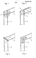
- FIG. 1 shows a known frame corner connection with only welded connections.
- a stem 10 is cut open in the upper region from its right side at the desired connection angle to the inner side of its outer flange 12.
- a bolt 16 is inserted into this free area and at the one indicated by the reference number 18 Places welded to the handle 10.
- a stiffening rib 20 is welded to the web and to the flanges of the bolt 16, as is indicated by the welding points 22. The disadvantages of this welded construction have already been described.
- FIG. 2 shows a known frame corner connection, which is partly welded and partly screwed.
- the handle 30 and the bolt 34 are mitred.
- an end plate 36 is welded, which is screwed to the abutting flange of the stem.
- This known construction has the disadvantage that it also requires a pull tab 38, which is welded to the stem 30 at the welding points 40 and screwed to the upper flange of the bolt 34 at points 42.
- this construction requires a lug 44 which is welded or screwed to the inside of the stem and which absorbs the vertical forces exerted by the bolt.
- FIG. 3 shows two miter cut I-beams, namely a handle 46 with welded end plate 47, and a bolt 48 with also. be welded - ter face plate 49. These two end plates 47 and 49 are screwed together. This construction is also complex, because of the two types of connection required by welding and screwing, as described at the beginning.
- FIG. 4 also shows two miter-cut I-beams, namely a handle 46 and a bolt 48, which are connected to one another by corners. Both are connected to one another by double-sided corner tabs 50, which are screwed to the adjacent web sections by the two I-beams . Since this connection takes place on the webs themselves, that is to say in the area of the neutral fiber, this known construction has the disadvantages described at the outset.
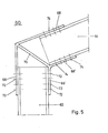
- FIG. 5 shows a shaped piece 60 according to the invention, with which a stem 62 and a latch 64 are connected to one another at an angle.
- the connection angle is equal to the angle of the shaped piece 60, which is formed by the angle of the two pairs of plates, namely by the pair of plates 66, 66 1 of the handle and by the pair of plates 68, 68 1 of the bolt.
- These two pairs of tabs are rigidly welded to one another by a web 70 or the shaped piece is designed as a casting.
- a particular advantage of the invention is that the I-beams 62 and 64 to be connected to one another do not have to be mitered. Rather, it is sufficient to push the fitting onto the upper end of the stem 62 and to screw the pair of tabs 66 and 66 1 at 72 to the flanges of the stem. Then one end of the bolt 64 is inserted into the right pair of tabs 68 and 68 1 of the shaped piece 60 and the screw connection between the bolts then takes place at points 74 and pair of tabs.
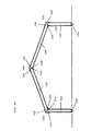
- FIG. 6 shows a gable roof-shaped frame which is composed of four I-beams and three shaped pieces 60.
- a stem 62 shown on the left in FIG. 6, is attached to a base 80. Its upper end is fastened in a pair of plates 66, 66 'of a shaped piece 60 used as a corner piece, in the other pair of plates 68 and 68' a bolt 64 is fastened at one end. At its other end, this bolt is connected in or on a pair of tabs 66, 66 'of a shaped piece 60 used as a ridge connection, which is designed in the same way as the shaped piece 60 used as a corner connection.
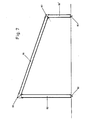
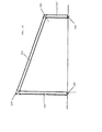
- FIG. 7 shows a pent-roof-shaped frame, which is also only composed of I-beams and fittings according to the invention.
- a stem 62 on the left in the figure, is connected at its upper end via a shaped piece 60, which has a relatively acute angle, to a latch 64 which slopes away to the right.
- This latch 64 is connected at its lower right end to a pair of tabs of a further fore piece 60, which has a relatively obtuse angle between the pair of tabs having.
- Connected to the other, lower pair of straps of this shaped piece 60 is a stem 62 ′ on the right in FIG. 7, the lower end of which is fastened at the base point 80.
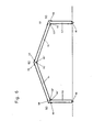
- FIG. 8 shows a gable roof-shaped frame similar to FIG. 6.
- shaped pieces 84 have been used which have two webs 86, 86 1 at an angle between the two pairs of tabs. These two webs 86, 86 'form an acute triangle with a base 88 connecting them, at the ends of which the respective lower tabs of the two pairs of tabs are fastened.
- the bars 64 are miter cut at their inner ends facing the roof ridge at such an angle that these ends abut on the adjacent web 86 or 86 1 of the ridge connecting piece.
- I-beams can also be used with the shaped piece according to the invention, which are mitered but at a different angle than that which is formed by the two webs of the shaped piece.
- the ends of the bars 64 or 64 'and the stems 62 or 62' do not have to rest against the webs 86 or 86 1 .
- FIG. 9 shows a shaped piece 160 according to the invention, with which a stem 162 and a bolt 164 are connected to one another at an angle.
- the connecting angle is equal to the angle of the shaped piece 160, which is determined by the angle of the two pairs of tabs is formed by the pair of tabs 166, 166 'of the handle and by the pair of tabs 168, 168' of the bolt.
- These two pairs of tabs are rigidly welded to one another by a web 170 or the shaped piece is designed as a casting.
- a particular advantage of the invention lies in the fact that the supports 162 and 164 to be connected to one another do not have to be mitered. Rather, it is sufficient to push the molded piece onto the upper end of the stem 162 and to screw the pair of tabs 166 and 166 'at 172 to the outside of the stem. Then one end of the latch 164 is inserted into the right pair of tabs 168 and 168 'of the shaped piece 160 and at points 174 the nail connection between the latch and the pair of tabs then takes place.
- FIG. 10 shows a gable roof-shaped frame which is composed of four wooden beams and three shaped pieces 160.
- a stem 162 shown on the left in FIG. 10, is attached to a base 180. Its upper end is fastened in a pair of plates 166, 166 'of a shaped piece 160 used as a corner piece, in the other pair of plates 168 and 168' a bolt 164 is fastened at one end. At its other end, this bolt is connected in or on a pair of tabs 16.6, 166 'of a shaped piece 160 used as a ridge connection, which is designed in the same way as the shaped piece 160 used as a corner connection.
- Figure II shows a pent roof-shaped frame, which is also composed of beams and fittings according to the invention.
- a stem 162 on the left in the figure, is connected at its upper end via a shaped piece 160, which has a relatively acute angle, to a latch 164 which slopes away to the right.
- This latch 164 is connected with its lower right end to a pair of tabs of a further shaped piece 160, which has a relatively obtuse angle between the pair of tabs.
- a stem 162 ′ is connected on the right in FIG. 11, the lower end of which is fastened at the base point 80.
- FIG. 12 shows a gable roof-shaped frame similar to FIG. 10.
- fittings 184 have been used, which have two webs 186, 186 'at an angle between the two pairs of tabs. These two webs 186, 186 'form an acute triangle with a base 188 connecting them, at the ends of which the respective lower tabs of the two tab pairs are fastened.
- the bars 164 are miter cut at their inner ends facing the roof ridge at such an angle that these ends abut on the adjacent web 186 or 186 'of the ridge connecting piece.
- supports can also be used with the shaped piece according to the invention which are mitred but at a different angle than that which is formed by the two webs of the shaped piece.
- the ends of the bars 164 and 164 'and the stems 162 and 162' do not have to rest against the webs 186 and 186 '.
- an additional support 163 is shown schematically, which supports the bolt 164 'via a pressure distribution plate 163'.
- Such supports or stems can be provided in the most varied of wooden frame constructions in order to enable larger frame constructions with the shaped pieces according to the invention.
- Such supports can, according to the present invention, also be used with pent roof frames according to FIG. 11 and also with saddle roof frames, which are not constructed with the aid of fittings with two webs, but with single-wall fittings, as shown in FIG. 9.
- the shaped pieces 160 according to the invention also make it possible to push a plurality of carriers lying against one another with their front ends together into a pair of tabs of a shaped piece and to fasten them. These bear against each other in this way connected to each other at the same time.
- these adjacent or adjacent supports can also be connected to one another in the area between the shaped pieces, for example by screws or by nails.
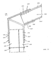
- frame constructions are also created with the aid of the shaped or corner pieces according to the invention, which include both wooden supports and metal supports, as shown in FIG.
- FIG. 13 shows a shaped piece 190, in the vertically arranged pair of lugs 192, 192 'of which two wooden beams 193 and 194 are inserted. These two wooden supports 193 and 194 are screwed at 195 to the bracket 192 and at 196 to the bracket 192 'of the vertical bracket pair. Below the pair of tabs, a bolt-screw connection 197, 198 of the two supports 192, 192 is provided, which together form a stem of the frame.
- the other pair of flaps 202, 202 ' which run obliquely upwards, has a smaller clear height than the vertically oriented pair of flaps.
- An I-beam 208 is inserted into this pair of tabs 202, 202 'in such a way that its two flanges 204 and 204' lie flat against the inside of the tabs 202 and 202 ', respectively.
- the upper flange 204 is welded to the tab 202 at 205, while the lower flange 204 'is screwed to the lower tab 204' by means of bolts 206 and nuts 207.
- holes for connecting the components can be formed both in the lugs of the lug pairs and in the outer sides of the supports, be they wooden supports or metal supports.
- the length of the brackets is chosen according to the materials of the beams and the desired stability of the frame structure to be created, taking into account the desired number of connections.
- the width of the tabs will generally be the same as the width of the outside of the carrier, but it can also be larger or smaller.
Landscapes
- Engineering & Computer Science (AREA)
- Architecture (AREA)
- Civil Engineering (AREA)
- Structural Engineering (AREA)
- Physics & Mathematics (AREA)
- Electromagnetism (AREA)
- Joining Of Building Structures In Genera (AREA)
- Mutual Connection Of Rods And Tubes (AREA)
Applications Claiming Priority (4)
| Application Number | Priority Date | Filing Date | Title |
|---|---|---|---|
| DE3321647A DE3321647A1 (de) | 1983-06-15 | 1983-06-15 | Biegefeste eckverbindungen |
| DE3321647 | 1983-06-15 | ||
| DE3325322A DE3325322A1 (de) | 1983-07-13 | 1983-07-13 | Biegefeste eckverbindungen fuer gebaeude in rahmenkonstruktion mit holztraegern |
| DE3325322 | 1983-07-13 |
Publications (2)
| Publication Number | Publication Date |
|---|---|
| EP0129176A2 true EP0129176A2 (fr) | 1984-12-27 |
| EP0129176A3 EP0129176A3 (fr) | 1985-07-24 |
Family
ID=25811514
Family Applications (1)
| Application Number | Title | Priority Date | Filing Date |
|---|---|---|---|
| EP84106625A Withdrawn EP0129176A3 (fr) | 1983-06-15 | 1984-06-08 | Fixation d'angle résistante à la flexion |
Country Status (1)
| Country | Link |
|---|---|
| EP (1) | EP0129176A3 (fr) |
Cited By (3)
| Publication number | Priority date | Publication date | Assignee | Title |
|---|---|---|---|---|
| EP0294575A1 (fr) * | 1987-04-24 | 1988-12-14 | Gang-Nail Systeme Gmbh | Connexion d'angle pour cadres à portique pour bâtiments, ainsi que son procédé de fabrication |
| EP0681064A3 (fr) * | 1994-05-03 | 1996-01-10 | Bernd Klein | Assemblage angulaire d'un système de support. |
| WO2003045767A1 (fr) * | 2001-11-30 | 2003-06-05 | Thyssenkrupp Stahl Ag | Element d'assemblage en tole d'acier pour profiles creux en tole d'acier, notamment structure de chassis de carrosserie de vehicule |
Family Cites Families (11)
| Publication number | Priority date | Publication date | Assignee | Title |
|---|---|---|---|---|
| NL62975C (fr) * | ||||
| US1657243A (en) * | 1924-12-06 | 1928-01-24 | Daniels Ernest Stuart | Joist and rafter suspension bracket |
| US2037736A (en) * | 1934-12-14 | 1936-04-21 | Crane Packing Co | Jointed structure |
| US2796642A (en) * | 1954-09-27 | 1957-06-25 | Timber Structures Inc | Rigid arch joiner |
| FR1191091A (fr) * | 1958-02-03 | 1959-10-16 | Perfectionnements aux charpentes | |
| FR1452129A (fr) * | 1965-07-06 | 1966-02-25 | Pneumatiques, Caoutchouc Manufacture Et Plastiques Kleber Colombes | Voûte, autoporteuse |
| DE2142278A1 (de) * | 1971-08-24 | 1973-03-01 | Tellberg Klas Olof | Verbindungsstueck |
| FR2184472B1 (fr) * | 1972-05-18 | 1976-06-11 | Cousquer Lucien | |
| CH552114A (de) * | 1972-12-22 | 1974-07-31 | A T A Ind Co Ltd | Stahlrahmen. |
| AU532373B2 (en) * | 1978-12-13 | 1983-09-29 | Anthony W. Clarke & Associates Pty. Ltd. | Portal building structural framing |
| DE3118972A1 (de) * | 1981-05-13 | 1982-11-25 | Soldimpex Paul Schockemöhle GmbH & Co KG, 2841 Steinfeld | Verbindungselement fuer stegprofile, insbesondere fuer im stahlbau verwendbare stegprofile, vorzugsweise i-traeger |
-
1984
- 1984-06-08 EP EP84106625A patent/EP0129176A3/fr not_active Withdrawn
Cited By (3)
| Publication number | Priority date | Publication date | Assignee | Title |
|---|---|---|---|---|
| EP0294575A1 (fr) * | 1987-04-24 | 1988-12-14 | Gang-Nail Systeme Gmbh | Connexion d'angle pour cadres à portique pour bâtiments, ainsi que son procédé de fabrication |
| EP0681064A3 (fr) * | 1994-05-03 | 1996-01-10 | Bernd Klein | Assemblage angulaire d'un système de support. |
| WO2003045767A1 (fr) * | 2001-11-30 | 2003-06-05 | Thyssenkrupp Stahl Ag | Element d'assemblage en tole d'acier pour profiles creux en tole d'acier, notamment structure de chassis de carrosserie de vehicule |
Also Published As
| Publication number | Publication date |
|---|---|
| EP0129176A3 (fr) | 1985-07-24 |
Similar Documents
| Publication | Publication Date | Title |
|---|---|---|
| DE69218467T2 (de) | Verbindungselement für Bauteile | |
| DD144176A5 (de) | Verbundtraeger | |
| DE3247231A1 (de) | Rahmenkonstruktion fuer einen personen-schraegfoerderer | |
| DE2128609A1 (de) | Verstärkte Schalungsplatte fur Be tonschalungen | |
| DE2313041A1 (de) | Mit einem gleichartigen zu einem geschlossenen kastenprofil zusammensteckbares profil | |
| DE69426073T2 (de) | Leichtmetallgitterträger und rahmensystem | |
| DE3048360A1 (de) | Transportable raumzelle zum aufbau von haeusern in massivholzbauweise | |
| EP0002814B1 (fr) | Coffrage pour béton formé de panneaux assemblés par clavettage | |
| DE2604320C3 (de) | Bauelementensatz für ein Hallenbauwerk, insbesondere ein landwirtschaftliches Stallbauwerk | |
| EP0129176A2 (fr) | Fixation d'angle résistante à la flexion | |
| CH640591A5 (en) | Wooden trussed girder | |
| DE69517964T2 (de) | Rahmen | |
| DD244589A5 (de) | Struktur fuer metallbauwerke im allgemeinen, insbesondere fuer fachwerke, mit profilen und verbindungselementen ausgefuehrt | |
| DE3325322A1 (de) | Biegefeste eckverbindungen fuer gebaeude in rahmenkonstruktion mit holztraegern | |
| DE19548334C2 (de) | Holzverbinder | |
| DE102021112759A1 (de) | Gerüstträger | |
| DE4205834C1 (en) | Framework of thin walled round fibre compound rods - has fibre compound joint plates connecting cross and diagonal bars to upright bars | |
| DE3321647A1 (de) | Biegefeste eckverbindungen | |
| AT408242B (de) | Eckelement eines schalungskastens | |
| DE202018100562U1 (de) | Gebäudestruktur mit einem Rahmen aus einer Mehrzahl miteinander verbundener Hohlprofilstäbe | |
| DE1509333B1 (de) | Eckverbindung fuer Metallrahmen von Fenstern,Tueren od.dgl. | |
| DE1509333C (de) | Eckverbindung für Metallrahmen von Fenstern, Türen od. dgl | |
| DE2006886C3 (de) | Geleimter Holzgitterträger für Bauzwecke | |
| DE8801741U1 (de) | Gitterträger | |
| EP0392628B1 (fr) | Coffrage pour parois à couler, et support vertical pour ce coffrage |
Legal Events
| Date | Code | Title | Description |
|---|---|---|---|
| PUAI | Public reference made under article 153(3) epc to a published international application that has entered the european phase |
Free format text: ORIGINAL CODE: 0009012 |
|
| AK | Designated contracting states |
Designated state(s): AT BE DE FR GB SE |
|
| PUAL | Search report despatched |
Free format text: ORIGINAL CODE: 0009013 |
|
| AK | Designated contracting states |
Designated state(s): AT BE DE FR GB SE |
|
| 17P | Request for examination filed |
Effective date: 19850624 |
|
| 17Q | First examination report despatched |
Effective date: 19870429 |
|
| STAA | Information on the status of an ep patent application or granted ep patent |
Free format text: STATUS: THE APPLICATION IS DEEMED TO BE WITHDRAWN |
|
| 18D | Application deemed to be withdrawn |
Effective date: 19870909 |
|
| RIN1 | Information on inventor provided before grant (corrected) |
Inventor name: WOLF, JOHANN |