EP0129180A1 - Dispositif pour l'introduction des barres de matériau dans une installation d'alimentation pour machines-outils, particulièrement des tours automatiques - Google Patents
Dispositif pour l'introduction des barres de matériau dans une installation d'alimentation pour machines-outils, particulièrement des tours automatiques Download PDFInfo
- Publication number
- EP0129180A1 EP0129180A1 EP84106641A EP84106641A EP0129180A1 EP 0129180 A1 EP0129180 A1 EP 0129180A1 EP 84106641 A EP84106641 A EP 84106641A EP 84106641 A EP84106641 A EP 84106641A EP 0129180 A1 EP0129180 A1 EP 0129180A1
- Authority
- EP
- European Patent Office
- Prior art keywords
- drive
- bar
- elevator
- levels
- drivers
- Prior art date
- Legal status (The legal status is an assumption and is not a legal conclusion. Google has not performed a legal analysis and makes no representation as to the accuracy of the status listed.)
- Granted
Links
- 239000000463 material Substances 0.000 title claims abstract description 33
- 241000282472 Canis lupus familiaris Species 0.000 abstract 3
- 230000001747 exhibiting effect Effects 0.000 abstract 1
- 230000000712 assembly Effects 0.000 description 1
- 238000000429 assembly Methods 0.000 description 1
- 239000000969 carrier Substances 0.000 description 1
Images


Classifications
-
- B—PERFORMING OPERATIONS; TRANSPORTING
- B65—CONVEYING; PACKING; STORING; HANDLING THIN OR FILAMENTARY MATERIAL
- B65G—TRANSPORT OR STORAGE DEVICES, e.g. CONVEYORS FOR LOADING OR TIPPING, SHOP CONVEYOR SYSTEMS OR PNEUMATIC TUBE CONVEYORS
- B65G1/00—Storing articles, individually or in orderly arrangement, in warehouses or magazines
- B65G1/02—Storage devices
- B65G1/04—Storage devices mechanical
- B65G1/0442—Storage devices mechanical for elongated articles
-
- B—PERFORMING OPERATIONS; TRANSPORTING
- B65—CONVEYING; PACKING; STORING; HANDLING THIN OR FILAMENTARY MATERIAL
- B65G—TRANSPORT OR STORAGE DEVICES, e.g. CONVEYORS FOR LOADING OR TIPPING, SHOP CONVEYOR SYSTEMS OR PNEUMATIC TUBE CONVEYORS
- B65G1/00—Storing articles, individually or in orderly arrangement, in warehouses or magazines
- B65G1/02—Storage devices
- B65G1/04—Storage devices mechanical
- B65G1/06—Storage devices mechanical with means for presenting articles for removal at predetermined position or level
- B65G1/08—Storage devices mechanical with means for presenting articles for removal at predetermined position or level the articles being fed by gravity
Definitions
- the invention relates to a device for feeding material bars into a replenishment device for machine tools, in particular automatic lathes, with a bar magazine consisting of a plurality of levels arranged obliquely one above the other and with an elevator arranged in front of the levels, which driver for grasping a bar from the magazine as well as has a bar discharge device at the upper end, which feeds a bar from the carriers of the replenishment device.
- German patent specification 23 50 105 a device is known which has several superposed levels for the storage of material bars, from which the bars are individually fed to a replenishment device with an elevator.
- the inclined planes each have a tongue which can be pivoted away from the path of the drivers on the elevator, so that the drivers can each remove a bar from one plane,
- rods can only be removed from the magazine in such a way that first the upper level and then the subsequent levels of material rods are emptied.
- Another disadvantage is that the driver has to be pivoted from the foremost stocked rod in order to thereby actuate a switch controlling the elevator drive. If the bar is very thin and there are only a few bars left in the relevant plane, there is a risk that the drivers, of which at least two must be present over the length of the elevator, push the bar back into the plane, thereby removing the bar is prevented from the plane. This creates disruptions in the operation of the elevator and the supply of material to the replenishment device, because one level is not completely made up of bars is emptied.
- the device mentioned at the outset is to be equipped with means which permit safe and complete emptying of a level of, in particular, light material bars.
- a device for feeding material bars into a supply device for machine tools, in particular automatic lathes with a bar magazine consisting of several levels arranged at an angle one above the other as well as with an elevator arranged in front of the levels, which driver for gripping a bar from the magazine and at the top End has a bar ejection device, which feeds a bar from the drivers of the replenishment device, it is provided that the driver designed as a slide are coupled to a drive adjustable to a predetermined distance. It is thereby achieved that rods can be removed from a predetermined level, rods of other diameters possibly remaining in the levels above them. Furthermore, the empty upper levels can be filled already with new material Stan g s, while material rods are taken to supply the replenishment device even from a lower level.
- a stepping mechanism which controls the elevator drive and is adjusted to the heights of the individual levels is provided, it becomes possible to automatically control individual levels from the beginning.
- the levels are arranged at a distance in front of the elevator, so that a material rod removed from a lower level 'in front of the ends of the upper level of the replenishment device can be fed by the elevator.
- a toothed strip is expediently formed on each driver, with which a toothed wheel coupled to the drive meshes.
- the slides and the shaft on which the toothed wheels meshing with the toothed strips of the drivers are seated in a rotationally fixed manner are advantageously fastened to the cross member of the elevator.
- a finger sits on the shaft in a rotationally fixed manner, in the path of which an adjustable stop protrudes.
- the adjustability of the stop allows the feed movement of the slide to be adapted to the diameter and thus to the position of the foremost rod to be removed from one plane.
- the stop is then expediently provided with a microswitch that controls the drive.
- a compressed air cylinder attached to the crossbar which is equipped with a travel limiter for the piston coupled to the shaft, has proven to be suitable as the drive.
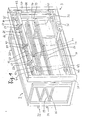
- the device for feeding material bars essentially consists of two assemblies, namely a bar magazine 2 and an elevator 3 set up in front of a longitudinal side of the bar magazine 2 2 in its longitudinal direction.
- the utility model document 82 25 574 shows, for example, an elevator 30 similar to the elevator 3 in its spatial assignment to a replenishment device.
- another type of attachment of the device to the replenishment device is also possible, as is shown, for example, in patent specification 23 50 105.
- the rod magazine 2 consists of a rectangular framework 20, in which several levels 22, 24 are fastened one above the other. Each level has a plurality of spaced, aligned strips 25, 26, 27 which are attached to a front cross member 28 and a rear cross member 29 of the framework 20. At the respective front end of each of the strips 25, 26, 27 there is a raised angle 31, 32. In this way, from behind, i.e. in Fig. 2 from the left, material bars 33 are placed on the strips 25, 26, 27, which due to the inclination of the strips 25, 26, 27 forward and down on the strips 25, 26, 27 forward to the system Roll angles 31, 32 so that on the levels 22, 24 there is a layer of adjacent material bars 33, 34 ready for removal of the foremost material bar lying against the angles 31, 32.
- the elevator 3 has a rectangular frame 35, on the side cheeks 37, 38 of which a vertical spindle 39 is fastened.
- the spindle 39 is coupled at the lower end via bevel gears 40 to an electric motor 36, which is the rotary drive for the spindle 39.
- the spindle 39 and the opposite spindle, not shown in FIG. 1, have a cross member 42 in such a way that when the spindles rotate, the cross member 42 is moved up or down in the frame 35 of the elevator 3.
- the drivers 50, 52, 54 spaced along its longitudinal direction, each of which has a throat for receiving a material bar at the end facing the bar magazine 2. Since the frame 35 of the elevator 3 is set up at a distance in front of the adjacent long side of the bar magazine 2, the drivers 50, 52, 54 can pass in front of the adjacent ends of the strips 25, 26, 27 when the crossbar 42 is being moved up and down.
- the driver 50 is designed as a slide which is displaceable in a longitudinal guide 56 fastened on the cross member 42 by a drive which can be set to a predetermined distance.
- the top of the driver 50 is provided behind the throat 58 with a toothed strip 60 with which a toothed wheel 62 is in engagement.
- the gear 62 and the further gears 63, 64 assigned to the further drivers 52, 54 are seated in a rotationally fixed manner on a shaft 66 which is rotatably mounted on the cross member 42 in posts 67, 68, 69, 70 and extends in the longitudinal direction of the cross member 42.
- the adjustable drive for the gears 62, b 3, 64 and the drivers 50 consists of a compressed air cylinder 72 fastened to the crossbeam 42 and also a stop 74 fastened to the cross member.
- the piston 73 of the compressed air cylinder 72 is non-rotatably connected to the shaft 66 connected arm 71 articulated so that the movement of the piston 73 in the air cylinder 72 results in a corresponding rotation of the shaft 66.
- the compressed air cylinder 72 is equipped with a travel limitation for the piston 73, so that the shaft 66 is rotated by a predetermined angle from the compressed air cylinder 72.
- the stop 74 interacts with a finger 76 which is seated in a rotationally fixed manner on the shaft 66 and is equipped with a microswitch (not shown) which actuates against the stop 74 when the finger 76 starts up. becomes.
- the stop 74 is attached to the cross member 42 relative to the shaft 66 on the same side as the air cylinder 72.
- the compressed air supply lines to the compressed air cylinder 72 and controllable valves which enable the compressed air cylinder 72 to be acted upon by compressed air in one direction or the other are not shown.
- the electrical control of the device in the input circuit of which the microswitch mentioned lies in the stop 74.
- the spindle 41 is indicated schematically, which in Fig. L is rotatably mounted behind the side cheek 38 of the frame 35 and can be driven synchronously with the spindle 39 by the electric motor 36.
- the device described works as follows: in the plane 24, material rods 33 of a diameter required for the automatic lathe are inserted, and in the level 22, material bars are inserted, for example, of a different diameter. If the supply device is to be supplied with a new material bar of a diameter which is equal to the diameter of the material bar 33 stored in the plane 24, the electric motor 36 is switched on in such a way that the cross member 42 is removed from the electric motor 36 and the spindles 39, 41 existing on 7 ugsantrieb in frame 35 is driven down. The compressed air cylinder 72 is acted on so that its piston 73 is fully extended and the drivers 50, 52, 54 are consequently in their fully retracted position.
- the spatial position of the planes 22, 24 relative to the cross member 42 is stored in a program control unit (not shown), which can also be an electronic type or a mechanical switching unit.
- a program control unit (not shown), which can also be an electronic type or a mechanical switching unit.
- a corresponding command is entered into the program control unit, which causes the cross member 42 with the retracted drivers 50, 52, 54 to descend to just below the front end of level 24.
- a microswitch can be installed, which is actuated by the foremost bar of material stored in the level 24 and the program control unit the presence of at least one level of material in the level 24 reports.
- a sensor can be arranged on the crossmember 42, which detects the presence of the foremost material bar in each of the levels 22, 24 and supplies a corresponding signal to the program control unit.
- the throats 58 of the drivers are now exactly below the foremost material bar of level 24.
- the program control mechanism moves the crossbar 42 up so far that the foremost material bar of level 24 is covered by the driver 50, 52, 54 and is lifted out of level 24.
- the program control unit then causes the piston 73 to be extended again from the compressed air cylinder 72 until the drivers 50, 52, 54 are again in their retracted position, with the required material bar now on the drivers 50, 52, 54, namely in whose throats 58, rests.
- the entrained material bar travels upwards at the front end of the level 22 located above the level 24 to an upper end position, where it is transferred to the inlet of the replenishment device in the manner shown in the aforementioned utility model.
- drivers 50, 52, 54 are spaced apart in the longitudinal direction of the cross member 42, that they can intervene in the space between the strips 25, 26, 27.
Landscapes
- Engineering & Computer Science (AREA)
- Mechanical Engineering (AREA)
- Turning (AREA)
Applications Claiming Priority (2)
| Application Number | Priority Date | Filing Date | Title |
|---|---|---|---|
| DE19833321164 DE3321164A1 (de) | 1983-06-11 | 1983-06-11 | Vorrichtung fuer die zufuhr von materialstangen in eine nachschubeinrichtung fuer werkzeugmaschinen, insbesondere drehautomaten |
| DE3321164 | 1983-06-11 |
Publications (2)
| Publication Number | Publication Date |
|---|---|
| EP0129180A1 true EP0129180A1 (fr) | 1984-12-27 |
| EP0129180B1 EP0129180B1 (fr) | 1986-10-01 |
Family
ID=6201257
Family Applications (1)
| Application Number | Title | Priority Date | Filing Date |
|---|---|---|---|
| EP84106641A Expired EP0129180B1 (fr) | 1983-06-11 | 1984-06-09 | Dispositif pour l'introduction des barres de matériau dans une installation d'alimentation pour machines-outils, particulièrement des tours automatiques |
Country Status (2)
| Country | Link |
|---|---|
| EP (1) | EP0129180B1 (fr) |
| DE (2) | DE3321164A1 (fr) |
Cited By (6)
| Publication number | Priority date | Publication date | Assignee | Title |
|---|---|---|---|---|
| DE3707655C1 (de) * | 1987-03-10 | 1988-01-14 | Heinz Dipl-Ing Dornieden | Langmateriallagereinrichtung |
| US5865596A (en) * | 1995-11-16 | 1999-02-02 | Sten Wallsten Nikom Ab | Separating and picking out device |
| CN109262198A (zh) * | 2018-09-08 | 2019-01-25 | 芜湖全程智能科技有限公司 | 一种用于轴类零件下料的下料设备及其使用方法 |
| CN112623696A (zh) * | 2020-10-30 | 2021-04-09 | 无锡航海精密钢管有限责任公司 | 一种管材稳定卸料装置 |
| CN113086658A (zh) * | 2021-04-19 | 2021-07-09 | 湖北宏博汽车工业智能装备有限公司 | 轴类仓式全自动上料机 |
| CN114030849A (zh) * | 2021-11-19 | 2022-02-11 | 中国联合工程有限公司 | 一种钢管内外壁涂覆生产线的上件装置 |
Families Citing this family (3)
| Publication number | Priority date | Publication date | Assignee | Title |
|---|---|---|---|---|
| AT405258B (de) * | 1994-01-27 | 1999-06-25 | Braeuer Franz | Vorrichtung zum ablängen von stangen und zuführen der abgelängten stangenstücke zu einer werkzeugmaschine |
| CN111573093B (zh) * | 2020-04-10 | 2021-08-20 | 涡阳县康仕达机电有限公司 | 一种车桥成品转运装置 |
| CN112475987B (zh) * | 2020-11-06 | 2023-01-06 | 窑街煤电集团甘肃金凯机械制造有限责任公司 | 一种锚杆加工生产线杆体自动送料装置 |
Citations (4)
| Publication number | Priority date | Publication date | Assignee | Title |
|---|---|---|---|---|
| US3750804A (en) * | 1969-03-07 | 1973-08-07 | Triax Co | Load handling mechanism and automatic storage system |
| DE2407756A1 (de) * | 1974-02-18 | 1975-08-28 | Norbert Karl Acker | Vorrichtung zum entspeichern von warenkanaelen |
| US4016987A (en) * | 1974-05-31 | 1977-04-12 | Stopa Stahlbau Gmbh & Co. | Storage system |
| DE2350105C2 (de) * | 1972-10-07 | 1983-03-17 | I.E.M.C.A. S.p.A. Industria Elettromeccanica Complessi Automatici, Faenza, Ravenna | Vorrichtung für die Zufuhr von Materialstangen in eine Nachschubeinrichtung für Werkzeugmaschinen |
-
1983
- 1983-06-11 DE DE19833321164 patent/DE3321164A1/de not_active Withdrawn
-
1984
- 1984-06-09 DE DE8484106641T patent/DE3460862D1/de not_active Expired
- 1984-06-09 EP EP84106641A patent/EP0129180B1/fr not_active Expired
Patent Citations (4)
| Publication number | Priority date | Publication date | Assignee | Title |
|---|---|---|---|---|
| US3750804A (en) * | 1969-03-07 | 1973-08-07 | Triax Co | Load handling mechanism and automatic storage system |
| DE2350105C2 (de) * | 1972-10-07 | 1983-03-17 | I.E.M.C.A. S.p.A. Industria Elettromeccanica Complessi Automatici, Faenza, Ravenna | Vorrichtung für die Zufuhr von Materialstangen in eine Nachschubeinrichtung für Werkzeugmaschinen |
| DE2407756A1 (de) * | 1974-02-18 | 1975-08-28 | Norbert Karl Acker | Vorrichtung zum entspeichern von warenkanaelen |
| US4016987A (en) * | 1974-05-31 | 1977-04-12 | Stopa Stahlbau Gmbh & Co. | Storage system |
Cited By (8)
| Publication number | Priority date | Publication date | Assignee | Title |
|---|---|---|---|---|
| DE3707655C1 (de) * | 1987-03-10 | 1988-01-14 | Heinz Dipl-Ing Dornieden | Langmateriallagereinrichtung |
| EP0281955A2 (fr) | 1987-03-10 | 1988-09-14 | Heinz Dornieden | Dispositif d'emmagasinage pour objets longs |
| US5865596A (en) * | 1995-11-16 | 1999-02-02 | Sten Wallsten Nikom Ab | Separating and picking out device |
| CN109262198A (zh) * | 2018-09-08 | 2019-01-25 | 芜湖全程智能科技有限公司 | 一种用于轴类零件下料的下料设备及其使用方法 |
| CN112623696A (zh) * | 2020-10-30 | 2021-04-09 | 无锡航海精密钢管有限责任公司 | 一种管材稳定卸料装置 |
| CN113086658A (zh) * | 2021-04-19 | 2021-07-09 | 湖北宏博汽车工业智能装备有限公司 | 轴类仓式全自动上料机 |
| CN113086658B (zh) * | 2021-04-19 | 2022-09-27 | 湖北宏博汽车工业智能装备有限公司 | 轴类仓式全自动上料机 |
| CN114030849A (zh) * | 2021-11-19 | 2022-02-11 | 中国联合工程有限公司 | 一种钢管内外壁涂覆生产线的上件装置 |
Also Published As
| Publication number | Publication date |
|---|---|
| DE3460862D1 (en) | 1986-11-06 |
| DE3321164A1 (de) | 1984-12-13 |
| EP0129180B1 (fr) | 1986-10-01 |
Similar Documents
| Publication | Publication Date | Title |
|---|---|---|
| DE3346523C2 (de) | Vorrichtung zum Zusammenbau eines Kraftfahrzeug-Körpers | |
| DE1777355B2 (de) | Transporteinrichtung zum Transportieren von Werkstücken zwischen zwei Pressen | |
| DE3422661A1 (de) | Vorrichtung zum zufuehren von abgelaengten laengsdraehten zu einer gitterschweissmaschine | |
| EP0129180B1 (fr) | Dispositif pour l'introduction des barres de matériau dans une installation d'alimentation pour machines-outils, particulièrement des tours automatiques | |
| EP0032656B1 (fr) | Installation pour la fabrication de brides de formes et de grandeurs différentes, spécialement des brides d'armature de béton | |
| EP0150809B1 (fr) | Dispositif pour évacuer et empiler des pièces de tôle tombant derrière la ligne de coupe d'une cisaille guillotine | |
| DE1813048B2 (de) | Vorrichtung zum abtrennen von an behaeltern aus thermoplastischem kunststoff befindlichen abfallteilen | |
| DE1939395B2 (de) | Magazinfülleinrichtung für Zigaretten weiterverarbeitende Maschinen | |
| DE1552422A1 (de) | Stangenlademagazin | |
| DE1950292A1 (de) | Saegemaschine | |
| DE1228275B (de) | Maschine zum geordneten Stapeln flacher Gegenstaende, beispielsweise von Zeitungen | |
| DE3010517C2 (de) | Falzmaschine mit einem Papieranleger | |
| AT362404B (de) | Zufuhrvorrichtung fuer blaetter od. dgl. | |
| DE8317102U1 (de) | Vorrichtung für die Zufuhr von Materialstangen in eine Nachschubeinrichtung für Werkzeugmaschinen, insbesondere Drehautomaten | |
| CH432366A (de) | Speicheranordnung | |
| DE19819596C2 (de) | Bogenrückhalter für einen Non-Stop-Stapelwechsler | |
| DE2724284A1 (de) | Beladevorrichtung | |
| DE3434446C2 (fr) | ||
| DE1602460B2 (de) | Anschlageinrichtung fuer eine abkantpresse | |
| DE19507740A1 (de) | Stapelvorrichtung für gefaltete Zeichnungen | |
| DE2408536C2 (de) | Vorrichtung zum gesteuerten Beschicken von Abfüll-, Baearbeitungs- und sonstigen Maschinen mit zu füllenden bzw. zu bearbeitenden becherförmigen Behältern | |
| DE1536429C (de) | Vorrichtung zum verschiedenartigen und -farbigen Bedrucken von Leersäcken aus z.B. Kunststoff-Folie oder Papier | |
| DE2119372C3 (de) | Vorrichtung zum automatischen Falten von Blattmaterial | |
| DE947153C (de) | Mit einem Werkstoffbehaelter versehene Beschickungseinrichtung einer Werkzeugmaschine | |
| DE2910091A1 (de) | Vorrichtung zur uebergabe eines spulenkoerpers |
Legal Events
| Date | Code | Title | Description |
|---|---|---|---|
| PUAI | Public reference made under article 153(3) epc to a published international application that has entered the european phase |
Free format text: ORIGINAL CODE: 0009012 |
|
| AK | Designated contracting states |
Designated state(s): CH DE FR GB IT LI |
|
| 17P | Request for examination filed |
Effective date: 19841120 |
|
| ITF | It: translation for a ep patent filed | ||
| RAP1 | Party data changed (applicant data changed or rights of an application transferred) |
Owner name: FECHENBACH-COLLENBERGER MASCHINENBAU GMBH |
|
| GRAA | (expected) grant |
Free format text: ORIGINAL CODE: 0009210 |
|
| AK | Designated contracting states |
Kind code of ref document: B1 Designated state(s): CH DE FR GB IT LI |
|
| REF | Corresponds to: |
Ref document number: 3460862 Country of ref document: DE Date of ref document: 19861106 |
|
| ET | Fr: translation filed | ||
| RAP2 | Party data changed (patent owner data changed or rights of a patent transferred) |
Owner name: FMB MASCHINENBAU GMBH |
|
| PLBE | No opposition filed within time limit |
Free format text: ORIGINAL CODE: 0009261 |
|
| STAA | Information on the status of an ep patent application or granted ep patent |
Free format text: STATUS: NO OPPOSITION FILED WITHIN TIME LIMIT |
|
| 26N | No opposition filed | ||
| ITTA | It: last paid annual fee | ||
| REG | Reference to a national code |
Ref country code: CH Ref legal event code: PUE Owner name: FMB MASCHINENBAU GMBH TRANSFER- FMB MASCHINENBAUGE |
|
| REG | Reference to a national code |
Ref country code: GB Ref legal event code: 732E |
|
| PGFP | Annual fee paid to national office [announced via postgrant information from national office to epo] |
Ref country code: GB Payment date: 20010521 Year of fee payment: 18 |
|
| PGFP | Annual fee paid to national office [announced via postgrant information from national office to epo] |
Ref country code: DE Payment date: 20010531 Year of fee payment: 18 |
|
| PGFP | Annual fee paid to national office [announced via postgrant information from national office to epo] |
Ref country code: FR Payment date: 20010618 Year of fee payment: 18 |
|
| PGFP | Annual fee paid to national office [announced via postgrant information from national office to epo] |
Ref country code: CH Payment date: 20010622 Year of fee payment: 18 |
|
| REG | Reference to a national code |
Ref country code: GB Ref legal event code: IF02 |
|
| PG25 | Lapsed in a contracting state [announced via postgrant information from national office to epo] |
Ref country code: GB Free format text: LAPSE BECAUSE OF NON-PAYMENT OF DUE FEES Effective date: 20020609 |
|
| PG25 | Lapsed in a contracting state [announced via postgrant information from national office to epo] |
Ref country code: LI Free format text: LAPSE BECAUSE OF NON-PAYMENT OF DUE FEES Effective date: 20020630 Ref country code: CH Free format text: LAPSE BECAUSE OF NON-PAYMENT OF DUE FEES Effective date: 20020630 |
|
| PG25 | Lapsed in a contracting state [announced via postgrant information from national office to epo] |
Ref country code: DE Free format text: LAPSE BECAUSE OF NON-PAYMENT OF DUE FEES Effective date: 20030101 |
|
| GBPC | Gb: european patent ceased through non-payment of renewal fee |
Effective date: 20020609 |
|
| REG | Reference to a national code |
Ref country code: CH Ref legal event code: PL |
|
| PG25 | Lapsed in a contracting state [announced via postgrant information from national office to epo] |
Ref country code: FR Free format text: LAPSE BECAUSE OF NON-PAYMENT OF DUE FEES Effective date: 20030228 |
|
| REG | Reference to a national code |
Ref country code: FR Ref legal event code: ST |