EP0129241A2 - Dispositif pour déplacer un protecteur de montée d'une première voie ascendante à une seconde voie ascendante - Google Patents
Dispositif pour déplacer un protecteur de montée d'une première voie ascendante à une seconde voie ascendante Download PDFInfo
- Publication number
- EP0129241A2 EP0129241A2 EP84106987A EP84106987A EP0129241A2 EP 0129241 A2 EP0129241 A2 EP 0129241A2 EP 84106987 A EP84106987 A EP 84106987A EP 84106987 A EP84106987 A EP 84106987A EP 0129241 A2 EP0129241 A2 EP 0129241A2
- Authority
- EP
- European Patent Office
- Prior art keywords
- climbing
- path
- slide
- section
- climbing path
- Prior art date
- Legal status (The legal status is an assumption and is not a legal conclusion. Google has not performed a legal analysis and makes no representation as to the accuracy of the status listed.)
- Granted
Links
Images
Classifications
-
- E—FIXED CONSTRUCTIONS
- E06—DOORS, WINDOWS, SHUTTERS, OR ROLLER BLINDS IN GENERAL; LADDERS
- E06C—LADDERS
- E06C7/00—Component parts, supporting parts, or accessories
- E06C7/18—Devices for preventing persons from falling
- E06C7/186—Rail or rope for guiding a safety attachment, e.g. a fall arrest system
- E06C7/187—Guiding rail
-
- E—FIXED CONSTRUCTIONS
- E06—DOORS, WINDOWS, SHUTTERS, OR ROLLER BLINDS IN GENERAL; LADDERS
- E06C—LADDERS
- E06C1/00—Ladders in general
- E06C1/02—Ladders in general with rigid longitudinal member or members
- E06C1/38—Special constructions of ladders, e.g. ladders with more or less than two longitudinal members, ladders with movable rungs or other treads, longitudinally-foldable ladders
- E06C1/381—Ladders with rungs or treads attached only to one rigid longitudinal member
Definitions
- the invention relates to a device for moving a climbing protection device from a first climbing path to a second climbing path, wherein the climbing protection device has a slide that slides along a longitudinal guide and has a releasable locking mechanism against a downward movement.
- fall protection devices are provided, which secures the person climbing the building against falling (DE-PS 1 961 757).
- transmission masts in particular, it is often necessary to move the climbing path in order to be able to climb upwards between the existing directional lamps.
- the slider In order to have a complete fall protection even when changing from the first ascent to the second ascent, the slider has been transferred from the end of the first ascent into a horizontal guide using a turntable-like device and at the end of it again using a turntable. Similar device introduced in the longitudinal guide of the second climb.
- the disadvantage here is that the turntable-like devices are complicated in structure. This type of displacement is also only possible with transmission masts with a relatively large diameter, since the slide cannot slide on transverse guides with a large curvature.
- the invention has for its object to provide a device for laterally moving a fall arrester from a first climb to a second climb, which is simple in construction and z. B. applicable to transmission towers of small diameter.
- This object is achieved in that a short section of the longitudinal guide can be displaced in parallel on a transverse guide between the first climb path and the second climb path.
- the transverse guide preferably has two spaced rails on which the section of the longitudinal guide is guided with rollers.
- a simpler embodiment of the transverse guide consists in a profiled rail which leads from the first ascent around the mast or the chimney to the second ascent and on which the slide slides by means of a plain bearing.
- the climbing paths can be formed by a central rail ladder according to DE-PS 1 961 757 or by a normal double rail ladder with an additional guide rail for the slide.
- a safety device at the upper and lower ends.
- the transverse guide can run straight on a flat wall or around a transmission mast, chimney or similar structure on a curved path.
- the radius of curvature can be practically arbitrarily small and z. B. be only 20 cm.
- the device can slide the slide at any angle around the transmission mast, Lead chimney or the like around, e.g. B. 90 0 , 180 0 or 360 0 .
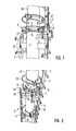
- a first climbing path 4 and a second climbing path 5 in the form of ladders with a central spar 11 and ladder rungs 12 are fastened to a concrete mast 10, as are known from DE-PS 1 961 757.
- the first climbing path 4 leads from the ground to the point shown in FIGS. 1 and 2, while the second climbing path 5 continues upwards from the point shown in FIGS. 1 and 2. Both climbing paths overlap by about 2 m.
- the device for displacing the climbing protection device has two curved round bars 6 which are arranged vertically one above the other and connected with webs and which serve as rails for guiding a slide 13.
- the round bars 6 are arranged concentrically around the concrete mast 10 and are fastened to it by pipe clamps 14.
- the round bars 6 can be adjusted in their distance from the concrete mast by adjustable spacing screws 15.
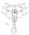
- the two rods 6 carry a carriage 13 (F ig. 4) is disposed from the end of the first climbing path 4 to a gap of the second riser path 5, the offset in the present embodiment by 180 0 to the concrete mast.
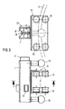
- the carriage 13 (FIG. 3) is guided by a total of 8 rollers 16 on the two round bars 6.
- the slide 13 is a U-shaped iron of sufficient length so that a total of eight rollers 16 can be arranged protruding inwards from the two legs of the U-shaped iron, two rollers 16 each clasping the round iron 6 together.
- each round bar 6 is clasped by two pairs of rollers, which are arranged at a distance of about 20 cm.
- the carriage 13 carries a small section 1 of the central spar of the ladder, and the distance of the round bars 6 from the concrete mast 10 is set such that the section 1 is in exact alignment with the central spars 11 of the first and second climbing paths 4, 5 by means of the carriage 13 can be brought.
- the central spar 11 also serves as a longitudinal guide for a slide 8 of a climbing protection device.
- the person climbing the ladder is secured to this slide 8 by means of a safety belt.
- the slide 8 has a locking pawl which is held in its locked position by spring action, in which the pawl nose protrudes into the interior of the U-profile of the longitudinal guide and rests against stop surfaces located there.
- further stop surfaces can be provided by rectangular hollow profile pieces 17 through further openings in the side walls of the U-profile of the central spar 11 are used.
- the section 1 is firmly screwed to the carriage 13 and contains in its interior a stop surface which is formed by such an additional hollow profile piece 17, so that the slide 8 is locked in the section 1.
- locking bolts 18 are provided at the upper and lower ends of the section 1, which are pressed radially outwards by a spring, ie pressed toward the person climbing the climb and pushed back by hand if the slide is to be moved over the lower or upper end of section 1.
- a lower climbing ring 19 and an upper climbing ring 20 are attached to the concrete mast 10 by pipe clamps.
- the lower climbing ring 19 is entered when changing trains and the upper climbing ring 20 is used for holding.
- the device for moving the climbing protection device is used when climbing upwards in such a way that when the person arrives at the upper end of the first climbing path 4, he brings the carriage 13 into the position on the left in FIGS. 1 and 2, in which the section 1 connects exactly to the upper end of the central spar 11 of the first climbing path 4. The person then moves the slider 8 of the fall arrest device from the central spar 11 into the section 1, to which end the locking bolt 18 at the lower end of the section 1 is pushed back. The pawl of the slide rests against the stop surface formed by the hollow profile piece 17 of the section 1, so that full security is provided.
- the slide 13 is automatically pulled along when changing from the first climbing path 4 to the second climbing path 5 and rolls over on the two parallel curved bars 6 to the second climbing path, so that the person is always secured with the same slide 8 from one climbing path 4 to the other climbing path 5 can switch over.
- the upper locking bolt 18 ensures that the slider 8 cannot slide out of the section 1 on the way.
- a stopper 21 provides at the upper end of the portion 1 for - the section 1 that exactly in the gap of this riser path 5 fits.
Landscapes
- Engineering & Computer Science (AREA)
- Mechanical Engineering (AREA)
- Forklifts And Lifting Vehicles (AREA)
- Ladders (AREA)
- Control And Safety Of Cranes (AREA)
- Burglar Alarm Systems (AREA)
- Supports Or Holders For Household Use (AREA)
- Emergency Lowering Means (AREA)
- Jib Cranes (AREA)
- Arrangement Or Mounting Of Control Devices For Change-Speed Gearing (AREA)
- Pharmaceuticals Containing Other Organic And Inorganic Compounds (AREA)
- Saccharide Compounds (AREA)
- Liquid Crystal (AREA)
- Buildings Adapted To Withstand Abnormal External Influences (AREA)
- Window Of Vehicle (AREA)
- Output Control And Ontrol Of Special Type Engine (AREA)
- Portable Nailing Machines And Staplers (AREA)
Priority Applications (1)
| Application Number | Priority Date | Filing Date | Title |
|---|---|---|---|
| AT84106987T ATE31101T1 (de) | 1983-06-21 | 1984-06-19 | Vorrichtung zum verschieben einer steigschutzeinrichtung von einem ersten steigweg zu einem zweiten steigweg. |
Applications Claiming Priority (2)
| Application Number | Priority Date | Filing Date | Title |
|---|---|---|---|
| DE3322298 | 1983-06-21 | ||
| DE3322298A DE3322298C1 (de) | 1983-06-21 | 1983-06-21 | Vorrichtung zum Verschieben einer Steigschutzeinrichtung von einem ersten Steigweg zu einem zweiten Steigweg |
Publications (3)
| Publication Number | Publication Date |
|---|---|
| EP0129241A2 true EP0129241A2 (fr) | 1984-12-27 |
| EP0129241A3 EP0129241A3 (en) | 1986-01-22 |
| EP0129241B1 EP0129241B1 (fr) | 1987-11-25 |
Family
ID=6201978
Family Applications (1)
| Application Number | Title | Priority Date | Filing Date |
|---|---|---|---|
| EP84106987A Expired EP0129241B1 (fr) | 1983-06-21 | 1984-06-19 | Dispositif pour déplacer un protecteur de montée d'une première voie ascendante à une seconde voie ascendante |
Country Status (7)
| Country | Link |
|---|---|
| EP (1) | EP0129241B1 (fr) |
| AT (1) | ATE31101T1 (fr) |
| DE (2) | DE3322298C1 (fr) |
| DK (1) | DK298484A (fr) |
| ES (1) | ES288746Y (fr) |
| NO (1) | NO842452L (fr) |
| ZA (1) | ZA844670B (fr) |
Cited By (3)
| Publication number | Priority date | Publication date | Assignee | Title |
|---|---|---|---|---|
| DE29719485U1 (de) * | 1997-11-03 | 1999-03-18 | Söll GmbH, 95028 Hof | Absturzsicherung |
| WO2000012176A1 (fr) | 1998-08-28 | 2000-03-09 | Söll Gmbh | Dispositif pour changer le plan de guidage d'un curseur guide sur le rail de guidage d'un systeme visant a empecher la chute d'un utilisateur |
| EP1222944A1 (fr) * | 2001-01-11 | 2002-07-17 | Sala Group Pty Limited | Procédé et dispositif d'ancrage pour câble de sûreté |
Families Citing this family (2)
| Publication number | Priority date | Publication date | Assignee | Title |
|---|---|---|---|---|
| DE8809386U1 (de) * | 1988-07-22 | 1988-12-15 | Soell Industrieschmiede Gmbh, 8670 Hof | Umsteigevorrichtung zum gesicherten Verlassen eines Steigweges beim Übergang auf eine Bühne, das Dach eines Bauwerkes, ein Podest o.dgl. |
| DE29712753U1 (de) * | 1997-07-18 | 1997-09-11 | Söll GmbH, 95028 Hof | Versenkbare Verlängerung der Führungsschiene einer Steigschutzvorrichtung |
Family Cites Families (4)
| Publication number | Priority date | Publication date | Assignee | Title |
|---|---|---|---|---|
| US3348632A (en) * | 1965-02-16 | 1967-10-24 | William E Swager | Climbing device |
| DE1961757C3 (de) * | 1969-12-09 | 1974-04-04 | Karl Soell, Gesenkschmiede, 8670 Hof | Leiter mit Steigschutzvorrichtung |
| DE2060718B2 (de) * | 1970-12-10 | 1973-08-02 | Fahrleitungsbau Gmbh, 4300 Essen | Absturzsicherung an leitern oder aehnlichen vorrichtungen |
| FR2495684A1 (fr) * | 1980-12-09 | 1982-06-11 | Risacher Marcel Charles | Protecteur coulissant et amovible pour echelles de moyenne et grande hauteur a un ou plusieurs elements |
-
1983
- 1983-06-21 DE DE3322298A patent/DE3322298C1/de not_active Expired
-
1984
- 1984-06-19 AT AT84106987T patent/ATE31101T1/de not_active IP Right Cessation
- 1984-06-19 ES ES1984288746U patent/ES288746Y/es not_active Expired
- 1984-06-19 DK DK298484A patent/DK298484A/da not_active Application Discontinuation
- 1984-06-19 EP EP84106987A patent/EP0129241B1/fr not_active Expired
- 1984-06-19 NO NO842452A patent/NO842452L/no unknown
- 1984-06-19 DE DE8484106987T patent/DE3467790D1/de not_active Expired
- 1984-06-20 ZA ZA844670A patent/ZA844670B/xx unknown
Cited By (8)
| Publication number | Priority date | Publication date | Assignee | Title |
|---|---|---|---|---|
| DE29719485U1 (de) * | 1997-11-03 | 1999-03-18 | Söll GmbH, 95028 Hof | Absturzsicherung |
| WO1999022816A2 (fr) | 1997-11-03 | 1999-05-14 | Söll Gmbh | Protection contre les chutes |
| US6571912B2 (en) | 1997-11-03 | 2003-06-03 | Christian Dalloz Holding Deutschland Gmbh & Co. Kg | Falling safeguard device |
| WO2000012176A1 (fr) | 1998-08-28 | 2000-03-09 | Söll Gmbh | Dispositif pour changer le plan de guidage d'un curseur guide sur le rail de guidage d'un systeme visant a empecher la chute d'un utilisateur |
| EP1222944A1 (fr) * | 2001-01-11 | 2002-07-17 | Sala Group Pty Limited | Procédé et dispositif d'ancrage pour câble de sûreté |
| US6604605B2 (en) | 2001-01-11 | 2003-08-12 | Sala Group Pty Limited | Safety line anchorage methods and apparatus |
| US6736239B2 (en) | 2001-01-11 | 2004-05-18 | Sala Group Pty Limited | Safety line anchorage methods and apparatus |
| US6802390B2 (en) | 2001-01-11 | 2004-10-12 | Capital Safety Group (Australia) Pty Limited | Safety line anchorage methods and apparatus |
Also Published As
| Publication number | Publication date |
|---|---|
| DE3467790D1 (en) | 1988-01-07 |
| DK298484A (da) | 1984-12-22 |
| DK298484D0 (da) | 1984-06-19 |
| ES288746U (es) | 1986-01-16 |
| DE3322298C1 (de) | 1984-07-19 |
| NO842452L (no) | 1984-12-27 |
| EP0129241A3 (en) | 1986-01-22 |
| ES288746Y (es) | 1986-10-01 |
| ZA844670B (en) | 1985-08-28 |
| EP0129241B1 (fr) | 1987-11-25 |
| ATE31101T1 (de) | 1987-12-15 |
Similar Documents
| Publication | Publication Date | Title |
|---|---|---|
| EP0076974B1 (fr) | Plateforme élévatrice pour personnes | |
| DE2400313A1 (de) | Hilfseinrichtung fuer einen seilnetzkuehlturm | |
| EP0457171B1 (fr) | Agencement à un coffrage pour la construction de murs | |
| DE3728282A1 (de) | Absturzsicherungsvorrichtung, insbesondere fuer dacharbeiten | |
| EP0129241B1 (fr) | Dispositif pour déplacer un protecteur de montée d'une première voie ascendante à une seconde voie ascendante | |
| DE60034433T2 (de) | Einrichtung und verfahren zum führungsschieneneinbau | |
| CH631943A5 (en) | Apparatus for travelling on a perpendicular or virtually perpendicular wall | |
| DE102008050178A1 (de) | Arbeitsgerüst | |
| DE69806532T2 (de) | Teleskopische Leiter und bewegliches Element geführt auf diese Leiter für einen Turmkran | |
| EP0996805B1 (fr) | Rallonge escamotable d'un rail de soutien pour harnais de securite | |
| DE4219732C2 (de) | Montagegerüst | |
| DE102008016601B3 (de) | Absturzsicherung | |
| DE2932707A1 (de) | Steigvorrichtung fuer ein bauwerk, insbesondere fuer einen mast, z.b. hochspannungsleitungsmast | |
| DE3026443C2 (de) | Mit einem Holm einer Gerüstleiter verbindbarer Leiterunterbau | |
| DE3543101C2 (de) | Verriegelungsvorrichtung für die aneinander zwangsgeführten Teleskopschüsse eines Aufzuges | |
| DE3403959A1 (de) | Wehr mit dammbalkenfuehrungen und hebe- und absenkvorrichtung | |
| DE2337892C2 (de) | Arbeitsgerüst mit heb- und senkbarer Arbeitsbühne | |
| EP4520894A1 (fr) | Dispositif de sécurité antichute, système de sécurité de toit et utilisation d'un dispositif de sécurité antichute | |
| DD289747A5 (de) | Auslegerrollbuehne fuer bauaufzuege | |
| DE902184C (de) | Einrichtung zur Montage von Gittermasten oder -tuermen | |
| DE2915607A1 (de) | Sicherungs- und rettungsgestell | |
| DD157871A3 (de) | Einrichtung fuer arbeitsgerueste mit heb- und senkbarer arbeitsbuehne | |
| DE29703596U1 (de) | Stirngeländer für ein Gerüst | |
| DE8115328U1 (de) | Leiterfuss | |
| DE7111416U (de) | Montagevorrichtung fur Turzargen |
Legal Events
| Date | Code | Title | Description |
|---|---|---|---|
| PUAI | Public reference made under article 153(3) epc to a published international application that has entered the european phase |
Free format text: ORIGINAL CODE: 0009012 |
|
| AK | Designated contracting states |
Designated state(s): AT BE CH DE FR GB IT LI LU NL SE |
|
| PUAL | Search report despatched |
Free format text: ORIGINAL CODE: 0009013 |
|
| AK | Designated contracting states |
Designated state(s): AT BE CH DE FR GB IT LI LU NL SE |
|
| 17P | Request for examination filed |
Effective date: 19860721 |
|
| 17Q | First examination report despatched |
Effective date: 19870218 |
|
| ITF | It: translation for a ep patent filed | ||
| GRAA | (expected) grant |
Free format text: ORIGINAL CODE: 0009210 |
|
| RAP1 | Party data changed (applicant data changed or rights of an application transferred) |
Owner name: SOELL INDUSTRIESCHMIEDE GMBH |
|
| AK | Designated contracting states |
Kind code of ref document: B1 Designated state(s): AT BE CH DE FR GB IT LI LU NL SE |
|
| PG25 | Lapsed in a contracting state [announced via postgrant information from national office to epo] |
Ref country code: NL Effective date: 19871125 Ref country code: BE Effective date: 19871125 |
|
| REF | Corresponds to: |
Ref document number: 31101 Country of ref document: AT Date of ref document: 19871215 Kind code of ref document: T |
|
| PG25 | Lapsed in a contracting state [announced via postgrant information from national office to epo] |
Ref country code: SE Effective date: 19871130 |
|
| REF | Corresponds to: |
Ref document number: 3467790 Country of ref document: DE Date of ref document: 19880107 |
|
| ET | Fr: translation filed | ||
| GBT | Gb: translation of ep patent filed (gb section 77(6)(a)/1977) | ||
| NLV1 | Nl: lapsed or annulled due to failure to fulfill the requirements of art. 29p and 29m of the patents act | ||
| PG25 | Lapsed in a contracting state [announced via postgrant information from national office to epo] |
Ref country code: AT Effective date: 19880619 |
|
| PG25 | Lapsed in a contracting state [announced via postgrant information from national office to epo] |
Ref country code: LU Free format text: LAPSE BECAUSE OF NON-PAYMENT OF DUE FEES Effective date: 19880630 |
|
| PLBE | No opposition filed within time limit |
Free format text: ORIGINAL CODE: 0009261 |
|
| STAA | Information on the status of an ep patent application or granted ep patent |
Free format text: STATUS: NO OPPOSITION FILED WITHIN TIME LIMIT |
|
| 26N | No opposition filed | ||
| ITTA | It: last paid annual fee | ||
| PGFP | Annual fee paid to national office [announced via postgrant information from national office to epo] |
Ref country code: FR Payment date: 20010529 Year of fee payment: 18 |
|
| PGFP | Annual fee paid to national office [announced via postgrant information from national office to epo] |
Ref country code: GB Payment date: 20010613 Year of fee payment: 18 |
|
| PGFP | Annual fee paid to national office [announced via postgrant information from national office to epo] |
Ref country code: DE Payment date: 20010627 Year of fee payment: 18 |
|
| PGFP | Annual fee paid to national office [announced via postgrant information from national office to epo] |
Ref country code: CH Payment date: 20010629 Year of fee payment: 18 |
|
| REG | Reference to a national code |
Ref country code: GB Ref legal event code: IF02 |
|
| PG25 | Lapsed in a contracting state [announced via postgrant information from national office to epo] |
Ref country code: GB Free format text: LAPSE BECAUSE OF NON-PAYMENT OF DUE FEES Effective date: 20020619 |
|
| PG25 | Lapsed in a contracting state [announced via postgrant information from national office to epo] |
Ref country code: LI Free format text: LAPSE BECAUSE OF NON-PAYMENT OF DUE FEES Effective date: 20020630 Ref country code: CH Free format text: LAPSE BECAUSE OF NON-PAYMENT OF DUE FEES Effective date: 20020630 |
|
| PG25 | Lapsed in a contracting state [announced via postgrant information from national office to epo] |
Ref country code: DE Free format text: LAPSE BECAUSE OF NON-PAYMENT OF DUE FEES Effective date: 20030101 |
|
| GBPC | Gb: european patent ceased through non-payment of renewal fee |
Effective date: 20020619 |
|
| REG | Reference to a national code |
Ref country code: CH Ref legal event code: PL |
|
| PG25 | Lapsed in a contracting state [announced via postgrant information from national office to epo] |
Ref country code: FR Free format text: LAPSE BECAUSE OF NON-PAYMENT OF DUE FEES Effective date: 20030228 |
|
| REG | Reference to a national code |
Ref country code: FR Ref legal event code: ST |