EP0129250A2 - Umformer-Regelungssystem - Google Patents
Umformer-Regelungssystem Download PDFInfo
- Publication number
- EP0129250A2 EP0129250A2 EP84107051A EP84107051A EP0129250A2 EP 0129250 A2 EP0129250 A2 EP 0129250A2 EP 84107051 A EP84107051 A EP 84107051A EP 84107051 A EP84107051 A EP 84107051A EP 0129250 A2 EP0129250 A2 EP 0129250A2
- Authority
- EP
- European Patent Office
- Prior art keywords
- value
- converter
- voltage
- current
- control system
- Prior art date
- Legal status (The legal status is an assumption and is not a legal conclusion. Google has not performed a legal analysis and makes no representation as to the accuracy of the status listed.)
- Granted
Links
Images


Classifications
-
- H—ELECTRICITY
- H02—GENERATION; CONVERSION OR DISTRIBUTION OF ELECTRIC POWER
- H02J—ELECTRIC POWER NETWORKS; CIRCUIT ARRANGEMENTS OR SYSTEMS FOR SUPPLYING OR DISTRIBUTING ELECTRIC POWER; SYSTEMS FOR STORING ELECTRIC ENERGY
- H02J3/00—Circuit arrangements for AC mains or AC distribution networks
- H02J3/36—Arrangements for transfer of electric power between AC networks via high-voltage DC [HVDC] links; Arrangements for transfer of electric power between generators and networks via HVDC links
-
- Y—GENERAL TAGGING OF NEW TECHNOLOGICAL DEVELOPMENTS; GENERAL TAGGING OF CROSS-SECTIONAL TECHNOLOGIES SPANNING OVER SEVERAL SECTIONS OF THE IPC; TECHNICAL SUBJECTS COVERED BY FORMER USPC CROSS-REFERENCE ART COLLECTIONS [XRACs] AND DIGESTS
- Y02—TECHNOLOGIES OR APPLICATIONS FOR MITIGATION OR ADAPTATION AGAINST CLIMATE CHANGE
- Y02E—REDUCTION OF GREENHOUSE GAS [GHG] EMISSIONS, RELATED TO ENERGY GENERATION, TRANSMISSION OR DISTRIBUTION
- Y02E60/00—Enabling technologies; Technologies with a potential or indirect contribution to GHG emissions mitigation
- Y02E60/60—Arrangements for transfer of electric power between AC networks or generators via a high voltage DC link [HVCD]
Definitions
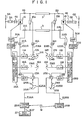
- a current margin value E25A or E25B obtained from a current margin presetter 25A or 25B is supplied via the closed one of switches 24A and 24B to the corresponding summing circuit 23A or 23B. Of switches 24A and 24B, only the one which allows the corresponding converter to operate as an inverter is closed.
- An advanced control angle preference circuit 28A receives outputs from regulators 11A, 12A and 13A. Advanced control angle preference circuit 28A selects only one of the received outputs in a manner that the selected one has the most phase-advanced control angle.
- An advanced control angle preference circuit 28B receives outputs from regulators 11B, 12B and 13B, and selects only one having the most phase-advanced control angle.
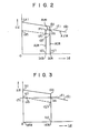
- portions (d), (e), (f) and (g) represent a constant current characteristic curve obtained by the actuation of automatic current regulator 13B.
- portions (e) and (f) represents a constant voltage characteristic curve obtained by the actuation of automatic voltage regulator 11B.
- Portions (f) and (g) represents a constant extinction angle characteristic obtained by the actuation of automatic extinction angle regulator 12B.
- the difference between a DC current IdA given by portions (b, c) and a DC current IdB given by portions (d, e) corresponds to the current margin which is generally set to be 5% to 10% of the rated DC current (IdA). For instance, if the rated current IdA is set at 1 0.0 A, the DC current IdB is 9.0 A to 9.5 A.
- Amplifier 33 serves to produce a positive signal +E33 when signal E32 is positive and serves to produce a negative signal -E33 when signal E32 is negative.
- limiter 34 has a function to limit the potential of its output which is used as reference correction value E31, so that output E31 does not become negative when signal E33 is negative and so that output E31 will not exceed a predetermined value (+E31P) when signal E33 is positive.
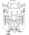
- transmission control circuits 26A and 26B of the prior art control system must have a function for maintaining a constant current margin. However, in the control system of the present invention, such a maintaining function need not be incorporated. It is sufficient to the present invention that an output signal E27 from reference current output circuit 27 is properly transmitted, received and memorized. As was described with reference to transmission control circuits 26A and 26B in Fig. 1, in order to constantly maintain a certain current margin, reference current values E26A and E26B are generally memorized in transmission control circuits 26A and 26B when reference current values E26A and E26B are supplied to summing circuits 23A and 23B. For the sake of simplicity, it is also assumed in the present invention that reference current values E26C and E26D are memorized in transmission control circuits 26C and 26D (cf. 26 in Fig. 5).
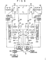
- each of transmission control circuits 26C and 26D is provided with a means for memorizing the reference current values E26C and E26D. If transmission control circuits 26C and 26D are not provided with such a means, reference current value E26D of converter 1B disappears when the communication system of transmission line 19 fails. When such failure occurs, the operation characteristic curve of converter 1B becomes one having portions (i"), (k), (f) and (g) as shown in Fig. 7, which is the same as that having portions (h), (f) and (g) in Fig. 3. Thus, even if the abovementioned memorizing means is not provided, unless the AC voltage at the forward converter side decreases substantially, stable power transfer can be performed.
Landscapes
- Engineering & Computer Science (AREA)
- Power Engineering (AREA)
- Supply And Distribution Of Alternating Current (AREA)
- Direct Current Feeding And Distribution (AREA)
- Inverter Devices (AREA)
Applications Claiming Priority (2)
| Application Number | Priority Date | Filing Date | Title |
|---|---|---|---|
| JP58111383A JPS605781A (ja) | 1983-06-21 | 1983-06-21 | 変換器の制御装置 |
| JP111383/83 | 1983-06-21 |
Publications (4)
| Publication Number | Publication Date |
|---|---|
| EP0129250A2 true EP0129250A2 (de) | 1984-12-27 |
| EP0129250A3 EP0129250A3 (en) | 1986-02-12 |
| EP0129250B1 EP0129250B1 (de) | 1989-02-08 |
| EP0129250B2 EP0129250B2 (de) | 1993-11-18 |
Family
ID=14559784
Family Applications (1)
| Application Number | Title | Priority Date | Filing Date |
|---|---|---|---|
| EP84107051A Expired - Lifetime EP0129250B2 (de) | 1983-06-21 | 1984-06-19 | Umformer-Regelungssystem |
Country Status (5)
| Country | Link |
|---|---|
| US (1) | US4578743A (de) |
| EP (1) | EP0129250B2 (de) |
| JP (1) | JPS605781A (de) |
| CA (1) | CA1217809A (de) |
| DE (1) | DE3476728D1 (de) |
Cited By (6)
| Publication number | Priority date | Publication date | Assignee | Title |
|---|---|---|---|---|
| EP0156396A3 (en) * | 1984-03-29 | 1986-11-26 | Kabushiki Kaisha Toshiba | Power converter control apparatus and power converter control method |
| EP0213877A3 (en) * | 1985-08-30 | 1989-03-22 | Kabushiki Kaisha Toshiba | Control device for power converter apparatus |
| EP0688081A1 (de) * | 1994-06-13 | 1995-12-20 | Siemens Aktiengesellschaft | Verfahren und Anordnung zur Gleichstromübertragung |
| EP0707370A3 (de) * | 1994-10-13 | 1997-05-02 | Asea Brown Boveri | Verfahren und Vorrichtung zur Steuerung einer Anlage zur Übertragung von Hochspannungsgleichstrom |
| GB2419043A (en) * | 2004-09-27 | 2006-04-12 | Areva T & D Uk Ltd | DC transmission system with variable current and voltage |
| US10931113B2 (en) | 2016-03-15 | 2021-02-23 | Mitsubishi Electric Corporation | Power conversion device and power system performing protection control for suppressing received power |
Families Citing this family (8)
| Publication number | Priority date | Publication date | Assignee | Title |
|---|---|---|---|---|
| JPS61285027A (ja) * | 1985-06-10 | 1986-12-15 | 株式会社東芝 | 交直変換装置の運転方法 |
| JP2507387B2 (ja) * | 1987-02-13 | 1996-06-12 | 株式会社東芝 | 電力変換装置 |
| US4884181A (en) * | 1987-08-26 | 1989-11-28 | Siemens Aktiengesellschaft | Method and arrangement for controlling a high voltage d-c transmission system |
| DE59002582D1 (de) * | 1989-07-11 | 1993-10-07 | Siemens Ag | Verfahren und vorrichtung zur ablösenden regelung mehrerer regelgrössen eines stromrichters. |
| JPH04355628A (ja) * | 1991-05-31 | 1992-12-09 | Toshiba Corp | 直流送電線路短絡検出装置 |
| JP3311214B2 (ja) * | 1995-09-05 | 2002-08-05 | 東京電力株式会社 | 電力変換装置の制御装置 |
| CN103257589B (zh) * | 2013-03-29 | 2015-12-23 | 国家电网公司 | 一种电压调节器仿真装置 |
| CN104518519B (zh) * | 2013-09-26 | 2017-11-03 | 南京南瑞继保电气有限公司 | 直流电压控制方法及装置 |
Family Cites Families (7)
| Publication number | Priority date | Publication date | Assignee | Title |
|---|---|---|---|---|
| DE1588750B2 (de) * | 1967-08-16 | 1971-04-29 | Siemens AG, 1000 Berlin u 8000 München | Verfahren und einrichtung zur uebertragung von gleichstrom |
| DE2901263C2 (de) * | 1979-01-13 | 1985-05-23 | Brown, Boveri & Cie Ag, 6800 Mannheim | Regelung einer HGÜ-(Hochspannungs-Gleichstrom- Übertragungs-)-Kurzkupplung |
| JPS55147920A (en) * | 1979-05-04 | 1980-11-18 | Hitachi Ltd | Dc transmission device operation control system |
| JPS58148625A (ja) * | 1982-02-26 | 1983-09-03 | 株式会社東芝 | 変換器の制御装置 |
| JPS59103520A (ja) * | 1982-12-03 | 1984-06-15 | 財団法人 電力中央研究所 | 変換所並列方式直流多端子系の電力潮流制御方式 |
| JPS6416092A (en) * | 1987-07-09 | 1989-01-19 | Matsushita Electric Industrial Co Ltd | Optical unit for video camera |
| JPH0825597B2 (ja) * | 1987-08-14 | 1996-03-13 | 株式会社タツノ・メカトロニクス | 給油装置の漏油検知方法 |
-
1983
- 1983-06-21 JP JP58111383A patent/JPS605781A/ja active Granted
-
1984
- 1984-06-19 EP EP84107051A patent/EP0129250B2/de not_active Expired - Lifetime
- 1984-06-19 DE DE8484107051T patent/DE3476728D1/de not_active Expired
- 1984-06-20 CA CA000457035A patent/CA1217809A/en not_active Expired
- 1984-06-21 US US06/622,877 patent/US4578743A/en not_active Expired - Lifetime
Cited By (6)
| Publication number | Priority date | Publication date | Assignee | Title |
|---|---|---|---|---|
| EP0156396A3 (en) * | 1984-03-29 | 1986-11-26 | Kabushiki Kaisha Toshiba | Power converter control apparatus and power converter control method |
| EP0213877A3 (en) * | 1985-08-30 | 1989-03-22 | Kabushiki Kaisha Toshiba | Control device for power converter apparatus |
| EP0688081A1 (de) * | 1994-06-13 | 1995-12-20 | Siemens Aktiengesellschaft | Verfahren und Anordnung zur Gleichstromübertragung |
| EP0707370A3 (de) * | 1994-10-13 | 1997-05-02 | Asea Brown Boveri | Verfahren und Vorrichtung zur Steuerung einer Anlage zur Übertragung von Hochspannungsgleichstrom |
| GB2419043A (en) * | 2004-09-27 | 2006-04-12 | Areva T & D Uk Ltd | DC transmission system with variable current and voltage |
| US10931113B2 (en) | 2016-03-15 | 2021-02-23 | Mitsubishi Electric Corporation | Power conversion device and power system performing protection control for suppressing received power |
Also Published As
| Publication number | Publication date |
|---|---|
| CA1217809A (en) | 1987-02-10 |
| EP0129250A3 (en) | 1986-02-12 |
| DE3476728D1 (en) | 1989-03-16 |
| EP0129250B2 (de) | 1993-11-18 |
| EP0129250B1 (de) | 1989-02-08 |
| US4578743A (en) | 1986-03-25 |
| JPS605781A (ja) | 1985-01-12 |
| JPH0570391B2 (de) | 1993-10-05 |
Similar Documents
| Publication | Publication Date | Title |
|---|---|---|
| US4578743A (en) | Converter control system having stable power transfer in the presence of decreased input AC voltage | |
| EP0762624B1 (de) | Steuersystem für Leistungswandlersystem | |
| EP0087640B1 (de) | Steuereinrichtung für einen Umformer | |
| US4263517A (en) | Control method and system for an high voltage direct current system | |
| EP0367247B1 (de) | Steuergerät für Kopplungssystem einer Gleichstromleistung | |
| EP0056659B1 (de) | Umformersteuergerät für ein Gleichstromsystem mit parallel geschalteten Einheiten | |
| US4728807A (en) | Power source system comprising a plurality of power sources having negative resistance characteristics | |
| US4649466A (en) | Method and circuit arrangemeant for operating a high voltage direct current line between two alternating voltage systems | |
| US4330815A (en) | DC Transmission control system | |
| US4598350A (en) | Power converter control apparatus and power converter control method | |
| US3644820A (en) | Control circuits for inverters | |
| GB2055257A (en) | Method and device for controlling a high voltage dc transmission system | |
| JP3187667B2 (ja) | 直流送電設備の変換器制御装置 | |
| JPH08308232A (ja) | 交直変換器の制御装置 | |
| JPH05207650A (ja) | 直流送電系統制御装置 | |
| EP0583875B1 (de) | Verfahren und Vorrichtung zur Leistungsumwandlungskontrolle | |
| JPS6343975B2 (de) | ||
| JP3276980B2 (ja) | 交直変換器の制御装置 | |
| SU1249661A1 (ru) | Способ управлени электронным вентилем | |
| JPH07107795A (ja) | 同期機用励磁制御装置及び制御方法 | |
| JPH0318433B2 (de) | ||
| JPS637140A (ja) | 無効電力補償装置 | |
| JPH0635556A (ja) | 同期調相機の制御装置 | |
| JPH0213531B2 (de) | ||
| JPS62236400A (ja) | 同期発電機の制御装置 |
Legal Events
| Date | Code | Title | Description |
|---|---|---|---|
| PUAI | Public reference made under article 153(3) epc to a published international application that has entered the european phase |
Free format text: ORIGINAL CODE: 0009012 |
|
| 17P | Request for examination filed |
Effective date: 19840619 |
|
| AK | Designated contracting states |
Designated state(s): CH DE LI SE |
|
| PUAL | Search report despatched |
Free format text: ORIGINAL CODE: 0009013 |
|
| AK | Designated contracting states |
Designated state(s): CH DE LI SE |
|
| 17Q | First examination report despatched |
Effective date: 19870915 |
|
| GRAA | (expected) grant |
Free format text: ORIGINAL CODE: 0009210 |
|
| AK | Designated contracting states |
Kind code of ref document: B1 Designated state(s): CH DE LI SE |
|
| REF | Corresponds to: |
Ref document number: 3476728 Country of ref document: DE Date of ref document: 19890316 |
|
| PLBI | Opposition filed |
Free format text: ORIGINAL CODE: 0009260 |
|
| 26 | Opposition filed |
Opponent name: SIEMENS AKTIENGESELLSCHAFT, BERLIN UND MUENCHEN Effective date: 19891108 |
|
| PUAH | Patent maintained in amended form |
Free format text: ORIGINAL CODE: 0009272 |
|
| STAA | Information on the status of an ep patent application or granted ep patent |
Free format text: STATUS: PATENT MAINTAINED AS AMENDED |
|
| 27A | Patent maintained in amended form |
Effective date: 19931118 |
|
| AK | Designated contracting states |
Kind code of ref document: B2 Designated state(s): CH DE LI SE |
|
| REG | Reference to a national code |
Ref country code: CH Ref legal event code: AEN |
|
| EAL | Se: european patent in force in sweden |
Ref document number: 84107051.9 |
|
| PGFP | Annual fee paid to national office [announced via postgrant information from national office to epo] |
Ref country code: CH Payment date: 19950614 Year of fee payment: 12 |
|
| PG25 | Lapsed in a contracting state [announced via postgrant information from national office to epo] |
Ref country code: LI Effective date: 19960630 Ref country code: CH Effective date: 19960630 |
|
| REG | Reference to a national code |
Ref country code: CH Ref legal event code: PL |
|
| PGFP | Annual fee paid to national office [announced via postgrant information from national office to epo] |
Ref country code: SE Payment date: 20000606 Year of fee payment: 17 |
|
| PGFP | Annual fee paid to national office [announced via postgrant information from national office to epo] |
Ref country code: DE Payment date: 20000616 Year of fee payment: 17 |
|
| PG25 | Lapsed in a contracting state [announced via postgrant information from national office to epo] |
Ref country code: SE Free format text: LAPSE BECAUSE OF NON-PAYMENT OF DUE FEES Effective date: 20010620 |
|
| EUG | Se: european patent has lapsed |
Ref document number: 84107051.9 |
|
| PG25 | Lapsed in a contracting state [announced via postgrant information from national office to epo] |
Ref country code: DE Free format text: LAPSE BECAUSE OF NON-PAYMENT OF DUE FEES Effective date: 20020403 |