EP0129282A1 - Messvorrichtung zur kontaktlosen Messung von grossen Dicken metallischer Stoffe oberhalb der Curie-Temperatur - Google Patents
Messvorrichtung zur kontaktlosen Messung von grossen Dicken metallischer Stoffe oberhalb der Curie-Temperatur Download PDFInfo
- Publication number
- EP0129282A1 EP0129282A1 EP84200819A EP84200819A EP0129282A1 EP 0129282 A1 EP0129282 A1 EP 0129282A1 EP 84200819 A EP84200819 A EP 84200819A EP 84200819 A EP84200819 A EP 84200819A EP 0129282 A1 EP0129282 A1 EP 0129282A1
- Authority
- EP
- European Patent Office
- Prior art keywords
- measuring device
- thickness
- coil
- wall
- sensor
- Prior art date
- Legal status (The legal status is an assumption and is not a legal conclusion. Google has not performed a legal analysis and makes no representation as to the accuracy of the status listed.)
- Granted
Links
- 238000005259 measurement Methods 0.000 title claims description 24
- 239000007769 metal material Substances 0.000 title 1
- 230000005291 magnetic effect Effects 0.000 claims abstract description 17
- 238000002847 impedance measurement Methods 0.000 claims abstract description 5
- 239000000463 material Substances 0.000 claims description 13
- 230000001419 dependent effect Effects 0.000 claims description 3
- 230000005292 diamagnetic effect Effects 0.000 claims description 2
- 239000003302 ferromagnetic material Substances 0.000 claims description 2
- 239000003517 fume Substances 0.000 claims description 2
- 230000003287 optical effect Effects 0.000 claims description 2
- 230000005298 paramagnetic effect Effects 0.000 claims description 2
- 230000001360 synchronised effect Effects 0.000 claims description 2
- CWYNVVGOOAEACU-UHFFFAOYSA-N Fe2+ Chemical compound [Fe+2] CWYNVVGOOAEACU-UHFFFAOYSA-N 0.000 claims 5
- 230000001939 inductive effect Effects 0.000 claims 1
- 238000004804 winding Methods 0.000 claims 1
- 238000000034 method Methods 0.000 description 7
- 230000004907 flux Effects 0.000 description 6
- 230000005294 ferromagnetic effect Effects 0.000 description 5
- 230000035515 penetration Effects 0.000 description 4
- 239000000470 constituent Substances 0.000 description 2
- 230000014509 gene expression Effects 0.000 description 2
- 238000005098 hot rolling Methods 0.000 description 2
- 229910001092 metal group alloy Inorganic materials 0.000 description 2
- 238000011144 upstream manufacturing Methods 0.000 description 2
- 239000004020 conductor Substances 0.000 description 1
- 238000010586 diagram Methods 0.000 description 1
- 230000002500 effect on skin Effects 0.000 description 1
- 230000000694 effects Effects 0.000 description 1
- 230000005307 ferromagnetism Effects 0.000 description 1
- 230000005251 gamma ray Effects 0.000 description 1
- 230000035699 permeability Effects 0.000 description 1
- 239000002244 precipitate Substances 0.000 description 1
- 230000005855 radiation Effects 0.000 description 1
- 238000002601 radiography Methods 0.000 description 1
- 230000035945 sensitivity Effects 0.000 description 1
Images


Classifications
-
- G—PHYSICS
- G01—MEASURING; TESTING
- G01B—MEASURING LENGTH, THICKNESS OR SIMILAR LINEAR DIMENSIONS; MEASURING ANGLES; MEASURING AREAS; MEASURING IRREGULARITIES OF SURFACES OR CONTOURS
- G01B7/00—Measuring arrangements characterised by the use of electric or magnetic techniques
- G01B7/02—Measuring arrangements characterised by the use of electric or magnetic techniques for measuring length, width or thickness
- G01B7/06—Measuring arrangements characterised by the use of electric or magnetic techniques for measuring length, width or thickness for measuring thickness
- G01B7/10—Measuring arrangements characterised by the use of electric or magnetic techniques for measuring length, width or thickness for measuring thickness using magnetic means, e.g. by measuring change of reluctance
-
- G—PHYSICS
- G01—MEASURING; TESTING
- G01B—MEASURING LENGTH, THICKNESS OR SIMILAR LINEAR DIMENSIONS; MEASURING ANGLES; MEASURING AREAS; MEASURING IRREGULARITIES OF SURFACES OR CONTOURS
- G01B7/00—Measuring arrangements characterised by the use of electric or magnetic techniques
- G01B7/02—Measuring arrangements characterised by the use of electric or magnetic techniques for measuring length, width or thickness
- G01B7/06—Measuring arrangements characterised by the use of electric or magnetic techniques for measuring length, width or thickness for measuring thickness
Definitions
- This invention relates to a measuring device for the "contactless" measurement of large thicknesses for use on conductive walls at a temperature exceeding the Curie temperature.
- a typical application of the measuring device is to measure the thickness (up to about 10 cm) of plates and tubes leaving hot rolling mills.
- the object of the present invention is to provide a measuring device for the "contactless" thickness measurement of conductive walls above the Curie temperature.
- a measuring device characterised by comprising a sensor constituted by a core with pole pieces which can be made to approach the wall to be examined and by an electric coil wound on the body of said core, means for supplying an alternative current to said coil,means for measuring the impedance of said coil, and processing means for obtaining the thickness of the wall under measurement from the measured value of said impedance.
- the metal alloy of the wall to be measured is above the Curie temperature.
- This physical condition means that the material is no longer ferromagnetic (nor contains ferromagnetic phases or precipitates), but instead is in a dia or paramagnetic state.
- the absence of ferromagnetism enables the lines of force of the magnetic field to penetrate into the material.
- the high temperature means that the metal alloy has a sufficiently high electrical resistivity to limit the dissipation of the magnetic field energy by the eddy current effect, and thus ensure good penetration of the alternating magnetic field.
- Figure 1 shows a sensor S constituted by a ferromagnetic coil N (of C shape), the pole pieces of which face the conductive wall P to be measured and are disposed a short distance therefrom.
- a coil B On the central portion of the ferromagnetic core N there is wound a coil B, which is fed with sinusoidal current I and has a measurable impedance Z.
- This described assembly corresponds to the equivalent magnetic circuit of Figure 2, which comprises a branch 1 equivalent to the ferromagnetic core N, a branch 2 equivalent to the passage through air of the magnetic flux between the core N and wall P, and a branch 3 equivalent to the passage in air downstream of the wall P; in the equivalent circuit model, the wall P is assumed thin relative to the air thicknesses and is thus negligible.
- the material of P is at a temperature higher than the Curie temperature, and the magnetic permeability of the air and of the material are approximately equal (u ⁇ 1), so that the presence of the wall does not alter the distribution of the magnetic field lines of flux.
- the three said branches are characterised by different values of magnetic reluctance, ie:
- the current I p itself depends on the derivative of 0 ⁇ 3 with respect to time, and on the resistance r offered by the wall P.
- vectorial notation from which, using the previous equation:
- the voltage V applied across the coil B can be calculated thus: It follows that the impedance Z of the coil B is given by the equation: in which the following parameters have been introduced: where ⁇ depends on the ratio of the reluctance of the magnetic paths upstream of the wall P to the reluctance external to the core and thus depends on the distance between the sensor and the wall, L is equal to the inductance of the coil B in the absence of the conductive wall, and T is a constant proportional to the inverse of the resistance presented by said wall, and thus proportional to the wall thickness.
- the above relationship (1) makes it possible to obtain the required thickness of the wall P from the measurement of the impedance Z of the coil B, by introducing the sensor-wall distance parameter as described hereinafter.
- the impedance of the third branch ⁇ /R 3 must be less than the resistance r of the equivalent turn: and thus The relationship is satisfied the smaller the value of T.
- the real part of the impedance becomes (where K « 1) with a very strong dependence (1/r) on the presence of the wall P.
- This phase difference is given by from which from which it is possible to deduce the required value of the thickness of the wall P once the sensor-wall distance is known.
- the thickness measurement and sensor-wall distance can be obtained by suitable mathematical manipulation or by using tables.
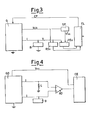
- the voltage V across the coil B which indicates the impedance of this latter, is rectified by two synchronous detectors RS and RS 2 which are piloted by the reference voltages V rif and V' rif respectively, and the relative outputs are fed to a processor EL which, in accordance with the proposed methods, is able to determine the value of the thickness of the wall P. If measurements at different frequencies are required, the processor EL can control the frequency of the sinusoidal generator G by means of a frequency control signal CF.
- a generator G generating sinusoidal current with angular frequency W feeds current I to the sensor coil B.
- the voltage V across the coil B which is indicative of the impedance of this latter, is rectified by RS and fed to a processor EL able to determine the thickness of the wall P.
- the senor can be constructed differently in order to improve the signal/noise ratio and stability, and to simplify the electrical circuits.
- Figure 6 shows the basic scheme of said sensor.
- An exciter coil B and two measurement coils Bland B 2 connected into a Wheatstone bridge are wound on a core.
- a potentiometer p enables the bridge to be zeroed when the input to be measured is absent.
- Figure 7 shows a different coil assembly scheme which has been tested experimentally and gives optimum performance.
- the core is y-shaped, the exciter coil B being mounted on the vertical central branch and the two bridge coils B 1 and B 2 being mounted on the adjacent horizontal branches of the 4.
- the senor should be cooled and protected from flames and fumes which may accompany the material to be measured.
- the description has referred heretofore to the measurement of a flat wall, it is possible to use analogous methods to measure the thickness of a tube,whether the tube is at rest or moving.
Landscapes
- Physics & Mathematics (AREA)
- General Physics & Mathematics (AREA)
- Measurement Of Length, Angles, Or The Like Using Electric Or Magnetic Means (AREA)
- Investigating Or Analyzing Materials By The Use Of Magnetic Means (AREA)
- Length-Measuring Instruments Using Mechanical Means (AREA)
- Length Measuring Devices By Optical Means (AREA)
- Length Measuring Devices With Unspecified Measuring Means (AREA)
Priority Applications (1)
| Application Number | Priority Date | Filing Date | Title |
|---|---|---|---|
| AT84200819T ATE37088T1 (de) | 1983-06-15 | 1984-06-08 | Messvorrichtung zur kontaktlosen messung von grossen dicken metallischer stoffe oberhalb der curie-temperatur. |
Applications Claiming Priority (2)
| Application Number | Priority Date | Filing Date | Title |
|---|---|---|---|
| IT21637/83A IT1194275B (it) | 1983-06-15 | 1983-06-15 | Misuratore di spessori elevati "senza contatto" per materiali metallici ad di sopra della temperatura di curie |
| IT2163783 | 1983-06-15 |
Publications (2)
| Publication Number | Publication Date |
|---|---|
| EP0129282A1 true EP0129282A1 (de) | 1984-12-27 |
| EP0129282B1 EP0129282B1 (de) | 1988-09-07 |
Family
ID=11184678
Family Applications (1)
| Application Number | Title | Priority Date | Filing Date |
|---|---|---|---|
| EP84200819A Expired EP0129282B1 (de) | 1983-06-15 | 1984-06-08 | Messvorrichtung zur kontaktlosen Messung von grossen Dicken metallischer Stoffe oberhalb der Curie-Temperatur |
Country Status (7)
| Country | Link |
|---|---|
| US (1) | US4771238A (de) |
| EP (1) | EP0129282B1 (de) |
| JP (1) | JPS6013203A (de) |
| AT (1) | ATE37088T1 (de) |
| CA (1) | CA1268816A (de) |
| DE (1) | DE3473921D1 (de) |
| IT (1) | IT1194275B (de) |
Cited By (2)
| Publication number | Priority date | Publication date | Assignee | Title |
|---|---|---|---|---|
| FR2572175A1 (fr) * | 1984-10-24 | 1986-04-25 | Stein Heurtey | Procede et dispositif pour mesurer l'epaisseur de couches metalliques minces deposees sur un support conducteur |
| CN111090063A (zh) * | 2018-10-24 | 2020-05-01 | Tdk株式会社 | 磁传感器 |
Families Citing this family (23)
| Publication number | Priority date | Publication date | Assignee | Title |
|---|---|---|---|---|
| SE451886B (sv) * | 1986-10-10 | 1987-11-02 | Sten Linder | Sett och anordning for beroringsfri metning av storheter hos eller i anslutning till elektriskt ledande material |
| US4843320A (en) * | 1987-12-17 | 1989-06-27 | Atlantic Richfield Company | Transient electromagnetic method for detecting corrosion on conductive containers |
| US4843319A (en) * | 1987-12-17 | 1989-06-27 | Atlantic Richfield Company | Transient electromagnetic method for detecting corrosion on conductive containers having variations in jacket thickness |
| CA1265916A (en) * | 1988-09-30 | 1990-02-20 | Jobst Ulrich Gellert | Method of manufacture of an electrical terminal on an injection molding nozzle |
| US5036236A (en) * | 1990-05-07 | 1991-07-30 | Hughes Aircraft Company | Air gap matching proximity sensor for magnetic bearings |
| EP0496934B1 (de) * | 1991-01-30 | 1994-10-12 | VDO Luftfahrtgeräte Werk GmbH | Verfahren zum Betreiben eines induktiven Abstandssensors |
| US5283519A (en) * | 1991-01-30 | 1994-02-01 | Vdo Luftfahrtgerate Werk Gmbh | Operation of inductive distance sensor by scaling output signal by vectorially obtained factor |
| US5420507A (en) * | 1992-09-28 | 1995-05-30 | Edward L. Laskowski | Method and apparatus for sensing a target characteristic by measuring both impedance and resonant frequency of a tank circuit |
| DE4327712C2 (de) * | 1993-08-18 | 1997-07-10 | Micro Epsilon Messtechnik | Sensoranordnung und Verfahren zum Erfassen von Eigenschaften der Oberflächenschicht eines metallischen Targets |
| US5701073A (en) * | 1996-02-28 | 1997-12-23 | Tektronix, Inc. | Direct current measuring apparatus and method employing flux diversion |
| JP2002533659A (ja) * | 1998-12-18 | 2002-10-08 | マイクロ−エプシロン・メステヒニク・ゲーエムベーハー・ウント・コンパニー・カー・ゲー | 渦電流センサの作動方法及び渦電流センサ |
| US7112960B2 (en) * | 2003-07-31 | 2006-09-26 | Applied Materials, Inc. | Eddy current system for in-situ profile measurement |
| CN100443853C (zh) * | 2004-04-21 | 2008-12-17 | 爱德森(厦门)电子有限公司 | 在线探测热钢板居里点温度层距表面深度的方法及装置 |
| WO2007019066A2 (en) * | 2005-08-04 | 2007-02-15 | Mau-Chung Frank Chang | Phase coherent differential structures |
| DE102008028711B4 (de) * | 2007-10-15 | 2009-07-09 | V&M Deutschland Gmbh | Verfahren und Vorrichtung zur Messung der Exzentrizität eines warmgefertigten, nahtlosen Rohres bei der Herstellung |
| US8284560B2 (en) * | 2008-11-14 | 2012-10-09 | Applied Materials, Inc. | Eddy current sensor with enhanced edge resolution |
| FR2972795B1 (fr) * | 2011-03-15 | 2013-10-11 | Crouzet Automatismes | Capteur inductif de proximite et procede de montage dudit capteur |
| ITUB20153041A1 (it) * | 2015-08-10 | 2017-02-10 | Danieli Automation Spa | Dispositivo per la misura a caldo, durante la laminazione, di una dimensione di profili metallici |
| GB201518809D0 (en) * | 2015-10-23 | 2015-12-09 | The Technology Partnership Plc | Temperature sensor |
| WO2018080764A1 (en) | 2016-10-28 | 2018-05-03 | Applied Materials, Inc. | Core configuration with alternating posts for in-situ electromagnetic induction monitoring system |
| JP7291558B2 (ja) * | 2019-07-03 | 2023-06-15 | 株式会社荏原製作所 | 渦電流センサ |
| JP7794432B2 (ja) * | 2021-12-22 | 2026-01-06 | 株式会社テイエルブイ | 厚さ測定装置 |
| CN116576768B (zh) * | 2023-04-06 | 2026-02-10 | 中机生产力促进中心有限公司 | 一种含保温层的管道壁厚检测系统及方法 |
Citations (2)
| Publication number | Priority date | Publication date | Assignee | Title |
|---|---|---|---|---|
| FR2163899A5 (de) * | 1971-12-06 | 1973-07-27 | Siderurgie Fse Inst Rech | |
| DE2226101A1 (de) * | 1972-05-29 | 1973-12-13 | Krauss Maffei Ag | Beruehrungsfreier abstandsgeber |
Family Cites Families (7)
| Publication number | Priority date | Publication date | Assignee | Title |
|---|---|---|---|---|
| GB1261346A (en) * | 1968-03-13 | 1972-01-26 | Atomic Energy Authority Uk | Improvements in or relating to the detection of magnetic discontinuities |
| US3764897A (en) * | 1971-12-28 | 1973-10-09 | Singer Co | Electromagnetic thickness gauging using a transmitting coil shaped to provide a constant field over a range of measuring distances |
| US3848182A (en) * | 1973-08-15 | 1974-11-12 | Magnetic Analysis Corp | Apparatus for limiting phase-angle response range, particularly in eddy current testing apparatus |
| JPS5753604A (en) * | 1980-09-18 | 1982-03-30 | Yokogawa Hokushin Electric Corp | Thickness gauge |
| US4461995A (en) * | 1981-10-29 | 1984-07-24 | Republic Steel Corporation | Cooling method and apparatus for eddy current flaw detection |
| US4578999A (en) * | 1982-02-10 | 1986-04-01 | Mannesmann A.G. | Instrument for testing materials |
| AT382458B (de) * | 1982-02-11 | 1987-02-25 | Voest Alpine Ag | Verfahren zur oberflaechenpruefung von ueber dem curie-punkt heissem stahlgut sowie einrichtung zur durchfuehrung des verfahrens |
-
1983
- 1983-06-15 IT IT21637/83A patent/IT1194275B/it active
-
1984
- 1984-06-08 EP EP84200819A patent/EP0129282B1/de not_active Expired
- 1984-06-08 AT AT84200819T patent/ATE37088T1/de active
- 1984-06-08 DE DE8484200819T patent/DE3473921D1/de not_active Expired
- 1984-06-11 US US06/619,345 patent/US4771238A/en not_active Expired - Fee Related
- 1984-06-13 CA CA000456428A patent/CA1268816A/en not_active Expired - Lifetime
- 1984-06-15 JP JP59122141A patent/JPS6013203A/ja active Pending
Patent Citations (2)
| Publication number | Priority date | Publication date | Assignee | Title |
|---|---|---|---|---|
| FR2163899A5 (de) * | 1971-12-06 | 1973-07-27 | Siderurgie Fse Inst Rech | |
| DE2226101A1 (de) * | 1972-05-29 | 1973-12-13 | Krauss Maffei Ag | Beruehrungsfreier abstandsgeber |
Non-Patent Citations (3)
| Title |
|---|
| JOURNAL OF SCIENTIFIC INSTRUMENTS, series 2, vol. 1, no. 11, November 1968, pages 1136-1137, London, GB; A de SA: "A radio-frequency method for determining Curie point temperatures" * |
| REVIEW OF SCIENTIFIC INSTRUMENTS, vol. 51, no. 4, April 1980, pages 521-527, American Institute of Physics, New York, US; S.R. RYAN et al.: "A magnetic-reluctance thickness gauge for high conductivity, ferromagnetic films" * |
| TRANSACTIONS AIEE, vol. 73, May 1954, pages 138-142, New York, US; W.A. YATES et al.: "Sheet and plated -metal measurements with a phase-angle-type probe" * |
Cited By (5)
| Publication number | Priority date | Publication date | Assignee | Title |
|---|---|---|---|---|
| US4752739A (en) * | 1984-10-16 | 1988-06-21 | Stein Heurtey | Device for measuring the thickness of thin metallic layers deposited on a conductive support |
| FR2572175A1 (fr) * | 1984-10-24 | 1986-04-25 | Stein Heurtey | Procede et dispositif pour mesurer l'epaisseur de couches metalliques minces deposees sur un support conducteur |
| EP0179720A1 (de) * | 1984-10-24 | 1986-04-30 | Stein Heurtey | Verfahren und Vorrichtung zur Dickenmessung von dünnen, auf einen leitenden Träger aufgebrachten, metallischen Schichten |
| CN111090063A (zh) * | 2018-10-24 | 2020-05-01 | Tdk株式会社 | 磁传感器 |
| CN111090063B (zh) * | 2018-10-24 | 2023-01-17 | Tdk株式会社 | 磁传感器 |
Also Published As
| Publication number | Publication date |
|---|---|
| US4771238A (en) | 1988-09-13 |
| JPS6013203A (ja) | 1985-01-23 |
| CA1268816A (en) | 1990-05-08 |
| ATE37088T1 (de) | 1988-09-15 |
| IT1194275B (it) | 1988-09-14 |
| IT8321637A1 (it) | 1984-12-15 |
| EP0129282B1 (de) | 1988-09-07 |
| DE3473921D1 (en) | 1988-10-13 |
| IT8321637A0 (it) | 1983-06-15 |
Similar Documents
| Publication | Publication Date | Title |
|---|---|---|
| EP0129282B1 (de) | Messvorrichtung zur kontaktlosen Messung von grossen Dicken metallischer Stoffe oberhalb der Curie-Temperatur | |
| EP0434439B1 (de) | Verfahren und Gerät zur Induktionsmessung durch eine Bekleidung hindurch | |
| JP4563633B2 (ja) | 対象物の誘導測定法 | |
| US4295095A (en) | Apparatus and method for detecting the location of metallic objects having alternating current passing therethrough | |
| US3686564A (en) | Multiple frequency magnetic field technique for differentiating between classes of metal objects | |
| US4752739A (en) | Device for measuring the thickness of thin metallic layers deposited on a conductive support | |
| EP0332048A3 (de) | Wirbelstromsonde mit mehreren Spulen und Verfahren zur Feststellung von Fehlstellen | |
| GB2187844A (en) | Process for contact-less measurement in a moving mode of the thickness and temperature of thin metal sheets by means of eddy currents | |
| JPH0812082B2 (ja) | 非接触式距離測定システム及び非接触式距離測定方法 | |
| US3764897A (en) | Electromagnetic thickness gauging using a transmitting coil shaped to provide a constant field over a range of measuring distances | |
| EP1810046B1 (en) | Sensor for measuring magnetic flux | |
| GB2411964A (en) | Fluxgate sensor | |
| EP0146638B1 (de) | Verfahren zum messen der umsetzungsrate | |
| EP0135204A2 (de) | Messvorrichtung für Fehlstellen auf der Oberfläche oder nahe der Oberfläche von metallischen Gegenständen, deren Temperatur höher ist als die Curie-Temperatur | |
| GB1595437A (en) | Electromagnetic detectors responsive to a modification of a magnetic field | |
| JP3072304B2 (ja) | 金属探知方法 | |
| EP0360574B1 (de) | Stromsensor mit einem Element aus amorphem magnetischem Metall | |
| CN111796223B (zh) | 用于测量铁磁环带的磁性的装置及其方法 | |
| GB2207510A (en) | Magnetic sensor | |
| JPH09210610A (ja) | 外部磁気や金属等の影響防止の高周波励磁差動トランス | |
| US3882375A (en) | Electromagnetic well logging system having receiver and nulling coils mounted on separate magnetic cores | |
| JP3035724B2 (ja) | 金属探知方法 | |
| US2929985A (en) | Method and a device for measuring the wall thickness of articles made of ferromagnetic materials | |
| JP3019714B2 (ja) | 磁性鋼板の増分透磁率計測装置 | |
| JPH0763833A (ja) | 超電導ループ型磁界測定装置 |
Legal Events
| Date | Code | Title | Description |
|---|---|---|---|
| PUAI | Public reference made under article 153(3) epc to a published international application that has entered the european phase |
Free format text: ORIGINAL CODE: 0009012 |
|
| AK | Designated contracting states |
Designated state(s): AT BE CH DE FR GB LI LU NL SE |
|
| 17P | Request for examination filed |
Effective date: 19850402 |
|
| 17Q | First examination report despatched |
Effective date: 19860806 |
|
| R17C | First examination report despatched (corrected) |
Effective date: 19870202 |
|
| RAP1 | Party data changed (applicant data changed or rights of an application transferred) |
Owner name: DALMINE S.P.A. Owner name: INNSE INNOCENTI SANTEUSTACCHIO S.P.A. Owner name: CISE- CENTRO INFORMAZIONI STUDI ESPERIENZE S.P.A. |
|
| GRAA | (expected) grant |
Free format text: ORIGINAL CODE: 0009210 |
|
| AK | Designated contracting states |
Kind code of ref document: B1 Designated state(s): AT BE CH DE FR GB LI LU NL SE |
|
| PG25 | Lapsed in a contracting state [announced via postgrant information from national office to epo] |
Ref country code: NL Effective date: 19880907 Ref country code: LI Effective date: 19880907 Ref country code: CH Effective date: 19880907 Ref country code: BE Effective date: 19880907 Ref country code: AT Effective date: 19880907 |
|
| REF | Corresponds to: |
Ref document number: 37088 Country of ref document: AT Date of ref document: 19880915 Kind code of ref document: T |
|
| REF | Corresponds to: |
Ref document number: 3473921 Country of ref document: DE Date of ref document: 19881013 |
|
| REG | Reference to a national code |
Ref country code: CH Ref legal event code: PL |
|
| ET | Fr: translation filed | ||
| NLV1 | Nl: lapsed or annulled due to failure to fulfill the requirements of art. 29p and 29m of the patents act | ||
| PG25 | Lapsed in a contracting state [announced via postgrant information from national office to epo] |
Ref country code: LU Free format text: LAPSE BECAUSE OF NON-PAYMENT OF DUE FEES Effective date: 19890630 |
|
| PLBE | No opposition filed within time limit |
Free format text: ORIGINAL CODE: 0009261 |
|
| STAA | Information on the status of an ep patent application or granted ep patent |
Free format text: STATUS: NO OPPOSITION FILED WITHIN TIME LIMIT |
|
| 26N | No opposition filed | ||
| PGFP | Annual fee paid to national office [announced via postgrant information from national office to epo] |
Ref country code: SE Payment date: 19910515 Year of fee payment: 8 |
|
| PGFP | Annual fee paid to national office [announced via postgrant information from national office to epo] |
Ref country code: GB Payment date: 19910604 Year of fee payment: 8 |
|
| PGFP | Annual fee paid to national office [announced via postgrant information from national office to epo] |
Ref country code: FR Payment date: 19910612 Year of fee payment: 8 |
|
| PGFP | Annual fee paid to national office [announced via postgrant information from national office to epo] |
Ref country code: DE Payment date: 19910619 Year of fee payment: 8 |
|
| REG | Reference to a national code |
Ref country code: FR Ref legal event code: TP |
|
| REG | Reference to a national code |
Ref country code: GB Ref legal event code: 732 |
|
| PG25 | Lapsed in a contracting state [announced via postgrant information from national office to epo] |
Ref country code: GB Effective date: 19920608 |
|
| PG25 | Lapsed in a contracting state [announced via postgrant information from national office to epo] |
Ref country code: SE Effective date: 19920609 |
|
| GBPC | Gb: european patent ceased through non-payment of renewal fee |
Effective date: 19920608 |
|
| PG25 | Lapsed in a contracting state [announced via postgrant information from national office to epo] |
Ref country code: FR Effective date: 19930226 |
|
| PG25 | Lapsed in a contracting state [announced via postgrant information from national office to epo] |
Ref country code: DE Effective date: 19930302 |
|
| REG | Reference to a national code |
Ref country code: FR Ref legal event code: ST |
|
| EUG | Se: european patent has lapsed |
Ref document number: 84200819.5 Effective date: 19930109 |