EP0129320A1 - Lautsprechergehaüse für Sprachübertragungsstationen - Google Patents
Lautsprechergehaüse für Sprachübertragungsstationen Download PDFInfo
- Publication number
- EP0129320A1 EP0129320A1 EP84303212A EP84303212A EP0129320A1 EP 0129320 A1 EP0129320 A1 EP 0129320A1 EP 84303212 A EP84303212 A EP 84303212A EP 84303212 A EP84303212 A EP 84303212A EP 0129320 A1 EP0129320 A1 EP 0129320A1
- Authority
- EP
- European Patent Office
- Prior art keywords
- enclosure
- loudspeaker
- foam material
- peripheral edge
- spider
- Prior art date
- Legal status (The legal status is an assumption and is not a legal conclusion. Google has not performed a legal analysis and makes no representation as to the accuracy of the status listed.)
- Granted
Links
Images
Classifications
-
- H—ELECTRICITY
- H04—ELECTRIC COMMUNICATION TECHNIQUE
- H04R—LOUDSPEAKERS, MICROPHONES, GRAMOPHONE PICK-UPS OR LIKE ACOUSTIC ELECTROMECHANICAL TRANSDUCERS; ELECTRIC HEARING AIDS; PUBLIC ADDRESS SYSTEMS
- H04R1/00—Details of transducers, loudspeakers or microphones
- H04R1/20—Arrangements for obtaining desired frequency or directional characteristics
- H04R1/22—Arrangements for obtaining desired frequency or directional characteristics for obtaining desired frequency characteristic only
- H04R1/28—Transducer mountings or enclosures modified by provision of mechanical or acoustic impedances, e.g. resonator, damping means
- H04R1/2807—Enclosures comprising vibrating or resonating arrangements
- H04R1/283—Enclosures comprising vibrating or resonating arrangements using a passive diaphragm
- H04R1/2834—Enclosures comprising vibrating or resonating arrangements using a passive diaphragm for loudspeaker transducers
-
- H—ELECTRICITY
- H04—ELECTRIC COMMUNICATION TECHNIQUE
- H04R—LOUDSPEAKERS, MICROPHONES, GRAMOPHONE PICK-UPS OR LIKE ACOUSTIC ELECTROMECHANICAL TRANSDUCERS; ELECTRIC HEARING AIDS; PUBLIC ADDRESS SYSTEMS
- H04R1/00—Details of transducers, loudspeakers or microphones
- H04R1/02—Casings; Cabinets ; Supports therefor; Mountings therein
Definitions
- the present invention relates generally to sound translating devices and more particularly to loudspeaker enclosure arrangements for use in voice communication terminals.
- a loudspeaker consists of a voice coil or motor unit operating an acoustic conical diaphragm, one side of which acts on an enclosed space known as the loudspeaker enclosure. Since the enclosure provides an acoustical load on the diaphragm, the operating characteristics of a loudspeaker are influenced by the acoustical properties of the enclosure.
- the loudspeakers are usually mounted on an inside surface of the housing, often in a cramped location, and the entire unit including a variety of electronic circuitry therefore becomes f a haphazard enclosure for the loudspeaker.
- this type of equipment is meant to'provide only voice communication as opposed to high-fidelity music and since manufacturers find it desirable to minimize the cost and size of their equipment, the loudspeaker employed therein tends to be an inexpensive miniature unit having an acceptable frequency response only in the voice frequency range.
- an electro-acoustic transducer for use in voice communication terminals adapted to receive voice frequency signals.
- a small loudspeaker has a voice coil structure and a conical diaphragm supported by a spider having a peripheral edge defining the shape of the loudspeaker.
- a piece of resilient open cell foam material having a shape complementary similar to that of the loudspeaker has one face provided with a concavity suitable for receiving the spider and the voice coil structure. The edge of the foam material is secured to the peripheral edge of the spider and the outer surface of the foam material is covered with a flexible layer of substantially air-impermeable material thereby providing the loudspeaker with an attached flexible back cavity enclosure.
- the flexible enclosure is effective to smooth out the frequency response and to remove the low frequency peak due to the resonant frequency of the loudspeaker. This is achieved without unduly affecting the normal low frequency response of the loudspeaker.
- the invention therefore provides an economical enclosure arrangement for a piece of telecommunication equipment wherein the response peak due to the resonant frequency of the loudspeaker is substantially eliminated and in which the overall frequency response is improved. Since the enclosure is small and flexible, the unit may be fitted in a cramped location of a piece of equipment. In addition, the loudspeaker will operate acceptably even if a portion of the flexible enclosure is deformed slightly against an adjacent component or if the enclosure is shaped to match its mounting space.
- FIG 1 shows a miniature loudspeaker 10 including a voice coil structure 11, and a spider 12 supporting a conical acoustic diaphragm 13.
- Such loudspeakers are available as commercial off-the-shelf items and may be circular or rectangular in shape. Common nominal sizes for these loudspeakers are about 21 inches in diameter or 21 inches by 3 inches.
- a peripheral edge 14 of the spider 12 defines the perimeter and shape of the loudspeaker 10.
- Shown in cross-section is a piece of flexible foam material 15 having an open cell or air-permeable construction.
- the foam material has a shape complementary similar to that of the loudspeaker; that is, it is either circular or rectangular and is provided with an opening at its approximate geometrical center as well as a conical depression to allow close-fitting engagement with the voice coil structure 11 and the spider 12.
- the foam material is thus somewhat donut-shaped.
- Foam material suitable to realize the invention is commercially available from various manufacturers. Its basic requirements are flexibility, open cell structure and small pore size to provide maximum sound energy absorption in minimum weight and thickness.
- the outer edge of the foam material is adhesively secured to the peripheral edge 14 of the loudspeaker 10.
- the joint between the foam material 15 and the spider 12 should preferably be air-impermeable.
- the outer surface of the foam material 15 is covered by a flexible layer 16 of air-impermeable material which seals the pores of the foam material 15.
- a flexible layer 16 of air-impermeable material which seals the pores of the foam material 15.
- Various rubber paints and compounds as well as some varnishes are ideally suited to the task.
- the sealing material and the foam material must be chemically compatible.
- silicone rubber compounds have been found to be ideally suited as sealing materials.
- the volume enclosed by the flexible layer 16 thus becomes the primary enclosure for loudspeaker 10.
- the efficiency of the enclosure may be increased by closing the circular opening at the center of the foam material 15. This may be achieved by adhesively securing a circular piece of air-impermeable material 17 over the opening.
- the piece 17 should be of a size adequate to seal the opening and may conveniently be made of ABS (Acrylonitrile-Butadine-Styrene) plastic. Alternately, the opening may be sealed simply with paper, cloth or plastic adhesive tape.
- a complete enclosure may also be created by using a thicker piece of foam material 15 such that a continuous skin or sealing layer may be obtained.
- the donut-shaped foam material lends itself to advantageous methods of manufacture as well as resulting in a more compact unit.
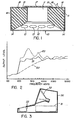
- FIG. 2 is a graphical representation of the improved performance of the transducer of the invention.
- Waveform 20 represents a nominal frequency response characteristics for a small unmodified loudspeaker mounted in a typical housing of a voice terminal. It is seen that the loudspeaker generates excessive acoustic output from about 200 to 650 hertz as well as a variety of other more minor variations across the voice frequency spectrum. These variations are due partly to the resonant frequency of the loudspeaker and partly to internal housing reflections due to the lack of a proper enclosure for the loudspeaker.
- Waveform 21 illustrates the smoothing effect provided by the enclosure arrangement of the invention. The resonant frequency effects are cancelled and the effects of housing reflections are substantially minimized without unduly affecting the low frequency response of the speaker.
- Waveform 22 illustrates the speaker response that might be expected if the primary enclosure was made of rigid material.
- the undesirable 400 hertz peak is eliminated, but at the expense of mutilating the low frequency response of the speaker.
- a primary enclosure having a flexible outer layer ensures that there is energy coupling between the primary and secondary enclosures.
- the amount of coupling varies in accordance with the degree of flexibility of the sealing layer.
- the amount of coupling may te further increased by providing the sealing layer with one or more breather holes as indicated at 18. Increasing the size of the hole(s) or the flexibility of the sealing layer increases the low frequency response of the transducer.
- the amount of coupling required is dependent on the loudspeaker characteristics and may be determined with a minimal amount of experimentation.
- FIG 3 illustrates an enclosure arrangement in accordance with the invention.
- a typical voice communication terminal comprising a housing 30 which contains a variety of electronic components 31, a CRT 32 and an electro-acoustic transducer 33 having a construction as shown in figure 1.
- the attached flexible enclosure of transducer 33 provides a primary enclosure which is energy coupled to a secondary enclosure formed by the interior volume of housing 30.
- the invention provides a loudspeaker having an improved frequency response characteristic. Because of its compact size and its flexible self-contained enclosure, the transducer may be fitted in a constrained location of a communication terminal. The flexible enclosure may be deformed slightly without causing the response of the loudspeaker to be greatly affected. Similarly, if it should be necessary due to space restrictions, it is entirely possible to shape the primary enclosure such as by cutting off a small portion. For example, the volume enclosed within the line A-A (fig. 1) and the outer surface 16 of the enclosure may simply be removed. Of course, the newly exposed surface of foam material 15 would then have to be re-sealed as with silicone rubber.
Landscapes
- Health & Medical Sciences (AREA)
- Otolaryngology (AREA)
- Physics & Mathematics (AREA)
- Engineering & Computer Science (AREA)
- Acoustics & Sound (AREA)
- Signal Processing (AREA)
- Diaphragms For Electromechanical Transducers (AREA)
- Telephone Set Structure (AREA)
- Details Of Audible-Bandwidth Transducers (AREA)
Priority Applications (1)
| Application Number | Priority Date | Filing Date | Title |
|---|---|---|---|
| AT84303212T ATE36794T1 (de) | 1983-06-16 | 1984-05-11 | Lautsprechergehauese fuer sprachuebertragungsstationen. |
Applications Claiming Priority (2)
| Application Number | Priority Date | Filing Date | Title |
|---|---|---|---|
| CA000430527A CA1196717A (en) | 1983-06-16 | 1983-06-16 | Loudspeaker enclosure arrangement for voice communication terminals |
| CA430527 | 1983-06-16 |
Publications (2)
| Publication Number | Publication Date |
|---|---|
| EP0129320A1 true EP0129320A1 (de) | 1984-12-27 |
| EP0129320B1 EP0129320B1 (de) | 1988-08-24 |
Family
ID=4125491
Family Applications (1)
| Application Number | Title | Priority Date | Filing Date |
|---|---|---|---|
| EP84303212A Expired EP0129320B1 (de) | 1983-06-16 | 1984-05-11 | Lautsprechergehaüse für Sprachübertragungsstationen |
Country Status (5)
| Country | Link |
|---|---|
| EP (1) | EP0129320B1 (de) |
| JP (1) | JPS6014596A (de) |
| AT (1) | ATE36794T1 (de) |
| CA (1) | CA1196717A (de) |
| DE (1) | DE3473718D1 (de) |
Cited By (3)
| Publication number | Priority date | Publication date | Assignee | Title |
|---|---|---|---|---|
| US4893695A (en) * | 1987-06-16 | 1990-01-16 | Matsushita Electric Industrial Co., Ltd. | Speaker system |
| US8767994B2 (en) | 2010-11-19 | 2014-07-01 | Apple Inc. | Gas filled speaker volume |
| US8837768B2 (en) | 2011-03-28 | 2014-09-16 | Bose Corporation | Electro-acoustic transducer enclosure |
Citations (6)
| Publication number | Priority date | Publication date | Assignee | Title |
|---|---|---|---|---|
| BE673136A (de) * | ||||
| FR1152433A (fr) * | 1956-06-20 | 1958-02-17 | Perfectionnement aux haut-parleurs | |
| GB790998A (en) * | 1953-10-23 | 1958-02-19 | Tesla Np | A device for the reproduction of sound |
| US4090582A (en) * | 1976-11-02 | 1978-05-23 | Deschu Dennis F | Speaker protector |
| FR2470511A1 (fr) * | 1979-11-20 | 1981-05-29 | Faugeras Alain | Enceinte acoustique du type " actif - passif " associee a un resonateur |
| DE2948034A1 (de) * | 1979-11-29 | 1981-06-11 | Telefonbau Und Normalzeit Gmbh, 6000 Frankfurt | Elektro-akustischer wandler mit zur verbesserung des frequenzverlaufes vorgesehenen resonanzraeumen |
Family Cites Families (1)
| Publication number | Priority date | Publication date | Assignee | Title |
|---|---|---|---|---|
| JPS5616876U (de) * | 1979-07-16 | 1981-02-14 |
-
1983
- 1983-06-16 CA CA000430527A patent/CA1196717A/en not_active Expired
-
1984
- 1984-05-11 DE DE8484303212T patent/DE3473718D1/de not_active Expired
- 1984-05-11 AT AT84303212T patent/ATE36794T1/de active
- 1984-05-11 EP EP84303212A patent/EP0129320B1/de not_active Expired
- 1984-06-15 JP JP59123539A patent/JPS6014596A/ja active Pending
Patent Citations (6)
| Publication number | Priority date | Publication date | Assignee | Title |
|---|---|---|---|---|
| BE673136A (de) * | ||||
| GB790998A (en) * | 1953-10-23 | 1958-02-19 | Tesla Np | A device for the reproduction of sound |
| FR1152433A (fr) * | 1956-06-20 | 1958-02-17 | Perfectionnement aux haut-parleurs | |
| US4090582A (en) * | 1976-11-02 | 1978-05-23 | Deschu Dennis F | Speaker protector |
| FR2470511A1 (fr) * | 1979-11-20 | 1981-05-29 | Faugeras Alain | Enceinte acoustique du type " actif - passif " associee a un resonateur |
| DE2948034A1 (de) * | 1979-11-29 | 1981-06-11 | Telefonbau Und Normalzeit Gmbh, 6000 Frankfurt | Elektro-akustischer wandler mit zur verbesserung des frequenzverlaufes vorgesehenen resonanzraeumen |
Cited By (4)
| Publication number | Priority date | Publication date | Assignee | Title |
|---|---|---|---|---|
| US4893695A (en) * | 1987-06-16 | 1990-01-16 | Matsushita Electric Industrial Co., Ltd. | Speaker system |
| AU597496B2 (en) * | 1987-06-16 | 1990-05-31 | Matsushita Electric Industrial Co., Ltd. | Speaker system |
| US8767994B2 (en) | 2010-11-19 | 2014-07-01 | Apple Inc. | Gas filled speaker volume |
| US8837768B2 (en) | 2011-03-28 | 2014-09-16 | Bose Corporation | Electro-acoustic transducer enclosure |
Also Published As
| Publication number | Publication date |
|---|---|
| DE3473718D1 (en) | 1988-09-29 |
| EP0129320B1 (de) | 1988-08-24 |
| CA1196717A (en) | 1985-11-12 |
| ATE36794T1 (de) | 1988-09-15 |
| JPS6014596A (ja) | 1985-01-25 |
Similar Documents
| Publication | Publication Date | Title |
|---|---|---|
| US4852177A (en) | High fidelity earphone and hearing aid | |
| US6134336A (en) | Integrated speaker assembly of a portable electronic device | |
| US4506759A (en) | Loudspeaker enclosure arrangement for voice communication terminals | |
| GB2200814A (en) | Background noise cancelling microphone | |
| CN111836159B (zh) | 发声模组 | |
| CN208798215U (zh) | 发声器件及便携终端 | |
| GB1591480A (en) | Compression driver for an acoustical horn speaker and a speaker having such a driver | |
| CN208285531U (zh) | 发声器 | |
| JPS62120193A (ja) | ヘツドホンのための耳当てクツシヨン | |
| GB2235852A (en) | Transducer having two or more ducts | |
| US3164221A (en) | Low frequency loudspeaker system | |
| WO2023050984A1 (zh) | 一种耳机 | |
| CN1242645C (zh) | 声音发生器 | |
| JPH0549142B2 (de) | ||
| CN216414548U (zh) | 圈铁喇叭组件及耳机 | |
| US4511768A (en) | Mounting arrangement for altering a microphone's frequency response | |
| CA1196083A (en) | Anti-side tone transmitter | |
| GB2064265A (en) | Microphone unit | |
| WO2022105101A1 (en) | Microphone integrted with loudspeaker | |
| EP0129320B1 (de) | Lautsprechergehaüse für Sprachübertragungsstationen | |
| CN210609588U (zh) | 发声装置和电子设备 | |
| US7035420B2 (en) | Microphone gasket with integrated acoustic resistance | |
| CN208638631U (zh) | 扬声器 | |
| JPH02170795A (ja) | パネル型スピーカ | |
| CN216414550U (zh) | 一种耳机 |
Legal Events
| Date | Code | Title | Description |
|---|---|---|---|
| PUAI | Public reference made under article 153(3) epc to a published international application that has entered the european phase |
Free format text: ORIGINAL CODE: 0009012 |
|
| AK | Designated contracting states |
Designated state(s): AT DE FR GB NL SE |
|
| 17P | Request for examination filed |
Effective date: 19850312 |
|
| 17Q | First examination report despatched |
Effective date: 19861103 |
|
| GRAA | (expected) grant |
Free format text: ORIGINAL CODE: 0009210 |
|
| AK | Designated contracting states |
Kind code of ref document: B1 Designated state(s): AT DE FR GB NL SE |
|
| REF | Corresponds to: |
Ref document number: 36794 Country of ref document: AT Date of ref document: 19880915 Kind code of ref document: T |
|
| REF | Corresponds to: |
Ref document number: 3473718 Country of ref document: DE Date of ref document: 19880929 |
|
| ET | Fr: translation filed | ||
| PLBE | No opposition filed within time limit |
Free format text: ORIGINAL CODE: 0009261 |
|
| STAA | Information on the status of an ep patent application or granted ep patent |
Free format text: STATUS: NO OPPOSITION FILED WITHIN TIME LIMIT |
|
| 26N | No opposition filed | ||
| PGFP | Annual fee paid to national office [announced via postgrant information from national office to epo] |
Ref country code: SE Payment date: 19900511 Year of fee payment: 7 |
|
| PGFP | Annual fee paid to national office [announced via postgrant information from national office to epo] |
Ref country code: AT Payment date: 19900515 Year of fee payment: 7 |
|
| PGFP | Annual fee paid to national office [announced via postgrant information from national office to epo] |
Ref country code: NL Payment date: 19900531 Year of fee payment: 7 |
|
| PGFP | Annual fee paid to national office [announced via postgrant information from national office to epo] |
Ref country code: DE Payment date: 19900629 Year of fee payment: 7 |
|
| PG25 | Lapsed in a contracting state [announced via postgrant information from national office to epo] |
Ref country code: AT Effective date: 19910511 |
|
| PG25 | Lapsed in a contracting state [announced via postgrant information from national office to epo] |
Ref country code: SE Effective date: 19910512 |
|
| PG25 | Lapsed in a contracting state [announced via postgrant information from national office to epo] |
Ref country code: NL Effective date: 19911201 |
|
| NLV4 | Nl: lapsed or anulled due to non-payment of the annual fee | ||
| PG25 | Lapsed in a contracting state [announced via postgrant information from national office to epo] |
Ref country code: DE Effective date: 19920303 |
|
| EUG | Se: european patent has lapsed |
Ref document number: 84303212.9 Effective date: 19911209 |
|
| PGFP | Annual fee paid to national office [announced via postgrant information from national office to epo] |
Ref country code: FR Payment date: 19990511 Year of fee payment: 16 |
|
| PGFP | Annual fee paid to national office [announced via postgrant information from national office to epo] |
Ref country code: GB Payment date: 19990512 Year of fee payment: 16 |
|
| PG25 | Lapsed in a contracting state [announced via postgrant information from national office to epo] |
Ref country code: GB Free format text: LAPSE BECAUSE OF NON-PAYMENT OF DUE FEES Effective date: 20000511 |
|
| GBPC | Gb: european patent ceased through non-payment of renewal fee |
Effective date: 20000511 |
|
| PG25 | Lapsed in a contracting state [announced via postgrant information from national office to epo] |
Ref country code: FR Free format text: LAPSE BECAUSE OF NON-PAYMENT OF DUE FEES Effective date: 20010131 |
|
| REG | Reference to a national code |
Ref country code: FR Ref legal event code: ST |