EP0129334B1 - Procédé d'usinage par décharges électriques à fil mobile et appareil avec une électrode à fil ferromagnétique - Google Patents
Procédé d'usinage par décharges électriques à fil mobile et appareil avec une électrode à fil ferromagnétique Download PDFInfo
- Publication number
- EP0129334B1 EP0129334B1 EP84303355A EP84303355A EP0129334B1 EP 0129334 B1 EP0129334 B1 EP 0129334B1 EP 84303355 A EP84303355 A EP 84303355A EP 84303355 A EP84303355 A EP 84303355A EP 0129334 B1 EP0129334 B1 EP 0129334B1
- Authority
- EP
- European Patent Office
- Prior art keywords
- electrode
- machining
- workpiece
- machining zone
- zone
- Prior art date
- Legal status (The legal status is an assumption and is not a legal conclusion. Google has not performed a legal analysis and makes no representation as to the accuracy of the status listed.)
- Expired
Links
- 238000000034 method Methods 0.000 title claims description 30
- 230000005294 ferromagnetic effect Effects 0.000 title claims description 12
- 238000003754 machining Methods 0.000 claims description 101
- 230000005291 magnetic effect Effects 0.000 claims description 41
- 239000000463 material Substances 0.000 claims description 29
- 229910000831 Steel Inorganic materials 0.000 claims description 17
- 239000010959 steel Substances 0.000 claims description 17
- 230000003628 erosive effect Effects 0.000 claims description 13
- 239000003302 ferromagnetic material Substances 0.000 claims description 11
- 238000011010 flushing procedure Methods 0.000 claims description 9
- 239000007788 liquid Substances 0.000 claims description 9
- 229910052751 metal Inorganic materials 0.000 claims description 9
- 239000002184 metal Substances 0.000 claims description 9
- XEEYBQQBJWHFJM-UHFFFAOYSA-N Iron Chemical compound [Fe] XEEYBQQBJWHFJM-UHFFFAOYSA-N 0.000 claims description 8
- 229910045601 alloy Inorganic materials 0.000 claims description 8
- 239000000956 alloy Substances 0.000 claims description 8
- 229910052761 rare earth metal Inorganic materials 0.000 claims description 5
- 229910052717 sulfur Inorganic materials 0.000 claims description 5
- 238000011144 upstream manufacturing Methods 0.000 claims description 5
- OKTJSMMVPCPJKN-UHFFFAOYSA-N Carbon Chemical compound [C] OKTJSMMVPCPJKN-UHFFFAOYSA-N 0.000 claims description 4
- OAICVXFJPJFONN-UHFFFAOYSA-N Phosphorus Chemical compound [P] OAICVXFJPJFONN-UHFFFAOYSA-N 0.000 claims description 4
- NINIDFKCEFEMDL-UHFFFAOYSA-N Sulfur Chemical compound [S] NINIDFKCEFEMDL-UHFFFAOYSA-N 0.000 claims description 4
- 229910052799 carbon Inorganic materials 0.000 claims description 4
- 238000009826 distribution Methods 0.000 claims description 4
- 229910052742 iron Inorganic materials 0.000 claims description 4
- WPBNNNQJVZRUHP-UHFFFAOYSA-L manganese(2+);methyl n-[[2-(methoxycarbonylcarbamothioylamino)phenyl]carbamothioyl]carbamate;n-[2-(sulfidocarbothioylamino)ethyl]carbamodithioate Chemical compound [Mn+2].[S-]C(=S)NCCNC([S-])=S.COC(=O)NC(=S)NC1=CC=CC=C1NC(=S)NC(=O)OC WPBNNNQJVZRUHP-UHFFFAOYSA-L 0.000 claims description 4
- 229910052710 silicon Inorganic materials 0.000 claims description 4
- 239000010703 silicon Substances 0.000 claims description 4
- 239000011593 sulfur Substances 0.000 claims description 4
- 230000005298 paramagnetic effect Effects 0.000 claims description 3
- 238000009763 wire-cut EDM Methods 0.000 claims description 3
- 239000011248 coating agent Substances 0.000 claims 1
- 238000000576 coating method Methods 0.000 claims 1
- 238000009877 rendering Methods 0.000 claims 1
- 238000009760 electrical discharge machining Methods 0.000 description 6
- CWYNVVGOOAEACU-UHFFFAOYSA-N Fe2+ Chemical compound [Fe+2] CWYNVVGOOAEACU-UHFFFAOYSA-N 0.000 description 4
- RYGMFSIKBFXOCR-UHFFFAOYSA-N Copper Chemical compound [Cu] RYGMFSIKBFXOCR-UHFFFAOYSA-N 0.000 description 3
- 230000002159 abnormal effect Effects 0.000 description 3
- 239000003990 capacitor Substances 0.000 description 3
- 229910052802 copper Inorganic materials 0.000 description 3
- 239000010949 copper Substances 0.000 description 3
- 238000010586 diagram Methods 0.000 description 3
- 230000000694 effects Effects 0.000 description 3
- 239000000696 magnetic material Substances 0.000 description 3
- 230000005389 magnetism Effects 0.000 description 3
- 230000005415 magnetization Effects 0.000 description 3
- 229910001369 Brass Inorganic materials 0.000 description 2
- 239000010951 brass Substances 0.000 description 2
- 239000002131 composite material Substances 0.000 description 2
- 238000001514 detection method Methods 0.000 description 2
- 239000000203 mixture Substances 0.000 description 2
- 238000012544 monitoring process Methods 0.000 description 2
- 238000009827 uniform distribution Methods 0.000 description 2
- 229910000859 α-Fe Inorganic materials 0.000 description 2
- 229910052684 Cerium Inorganic materials 0.000 description 1
- VYZAMTAEIAYCRO-UHFFFAOYSA-N Chromium Chemical compound [Cr] VYZAMTAEIAYCRO-UHFFFAOYSA-N 0.000 description 1
- 229910000531 Co alloy Inorganic materials 0.000 description 1
- 229910000677 High-carbon steel Inorganic materials 0.000 description 1
- 229910001122 Mischmetal Inorganic materials 0.000 description 1
- 229910052772 Samarium Inorganic materials 0.000 description 1
- 229910001069 Ti alloy Inorganic materials 0.000 description 1
- WBWJXRJARNTNBL-UHFFFAOYSA-N [Fe].[Cr].[Co] Chemical compound [Fe].[Cr].[Co] WBWJXRJARNTNBL-UHFFFAOYSA-N 0.000 description 1
- UWIMQBMUGNMYPA-UHFFFAOYSA-N [Ti].[Mn].[Fe] Chemical compound [Ti].[Mn].[Fe] UWIMQBMUGNMYPA-UHFFFAOYSA-N 0.000 description 1
- 239000004411 aluminium Substances 0.000 description 1
- 229910052782 aluminium Inorganic materials 0.000 description 1
- XAGFODPZIPBFFR-UHFFFAOYSA-N aluminium Chemical compound [Al] XAGFODPZIPBFFR-UHFFFAOYSA-N 0.000 description 1
- GWXLDORMOJMVQZ-UHFFFAOYSA-N cerium Chemical compound [Ce] GWXLDORMOJMVQZ-UHFFFAOYSA-N 0.000 description 1
- 229910052804 chromium Inorganic materials 0.000 description 1
- 239000011651 chromium Substances 0.000 description 1
- VNTLIPZTSJSULJ-UHFFFAOYSA-N chromium molybdenum Chemical compound [Cr].[Mo] VNTLIPZTSJSULJ-UHFFFAOYSA-N 0.000 description 1
- 239000010941 cobalt Substances 0.000 description 1
- 229910017052 cobalt Inorganic materials 0.000 description 1
- GUTLYIVDDKVIGB-UHFFFAOYSA-N cobalt atom Chemical compound [Co] GUTLYIVDDKVIGB-UHFFFAOYSA-N 0.000 description 1
- 239000012141 concentrate Substances 0.000 description 1
- 238000013016 damping Methods 0.000 description 1
- 239000008367 deionised water Substances 0.000 description 1
- 229910021641 deionized water Inorganic materials 0.000 description 1
- 238000006073 displacement reaction Methods 0.000 description 1
- 239000012530 fluid Substances 0.000 description 1
- 230000004907 flux Effects 0.000 description 1
- 238000010438 heat treatment Methods 0.000 description 1
- 230000001771 impaired effect Effects 0.000 description 1
- 229910052746 lanthanum Inorganic materials 0.000 description 1
- FZLIPJUXYLNCLC-UHFFFAOYSA-N lanthanum atom Chemical compound [La] FZLIPJUXYLNCLC-UHFFFAOYSA-N 0.000 description 1
- KZUNJOHGWZRPMI-UHFFFAOYSA-N samarium atom Chemical compound [Sm] KZUNJOHGWZRPMI-UHFFFAOYSA-N 0.000 description 1
- 239000010935 stainless steel Substances 0.000 description 1
- 229910001220 stainless steel Inorganic materials 0.000 description 1
- 239000000126 substance Substances 0.000 description 1
- 230000001960 triggered effect Effects 0.000 description 1
- XLYOFNOQVPJJNP-UHFFFAOYSA-N water Chemical compound O XLYOFNOQVPJJNP-UHFFFAOYSA-N 0.000 description 1
- 229910052727 yttrium Inorganic materials 0.000 description 1
- VWQVUPCCIRVNHF-UHFFFAOYSA-N yttrium atom Chemical compound [Y] VWQVUPCCIRVNHF-UHFFFAOYSA-N 0.000 description 1
Images
Classifications
-
- B—PERFORMING OPERATIONS; TRANSPORTING
- B23—MACHINE TOOLS; METAL-WORKING NOT OTHERWISE PROVIDED FOR
- B23H—WORKING OF METAL BY THE ACTION OF A HIGH CONCENTRATION OF ELECTRIC CURRENT ON A WORKPIECE USING AN ELECTRODE WHICH TAKES THE PLACE OF A TOOL; SUCH WORKING COMBINED WITH OTHER FORMS OF WORKING OF METAL
- B23H7/00—Processes or apparatus applicable to both electrical discharge machining and electrochemical machining
- B23H7/02—Wire-cutting
- B23H7/08—Wire electrodes
-
- B—PERFORMING OPERATIONS; TRANSPORTING
- B23—MACHINE TOOLS; METAL-WORKING NOT OTHERWISE PROVIDED FOR
- B23H—WORKING OF METAL BY THE ACTION OF A HIGH CONCENTRATION OF ELECTRIC CURRENT ON A WORKPIECE USING AN ELECTRODE WHICH TAKES THE PLACE OF A TOOL; SUCH WORKING COMBINED WITH OTHER FORMS OF WORKING OF METAL
- B23H7/00—Processes or apparatus applicable to both electrical discharge machining and electrochemical machining
- B23H7/02—Wire-cutting
- B23H7/04—Apparatus for supplying current to working gap; Electric circuits specially adapted therefor
Definitions
- the present invention relates to travelling-wire electrical discharge machining (TW-EDM), or a process of electrical-discharge-machining a conductive workpiece by means of a thin, elongate continuous electrode element (hereinafter referred to as "wire electrode” or “wire”), the wire being axially advanced from supply means to travel through a machining zone in the workpiece and to be taken up on to takeup means, in which process a succession of time-spaced electrical discharges are effected between the travelling wire and the workpiece across a machining gap in the presence of a flushing liquid medium to electroerosively remove material from the workpiece while the wire and the workpiece are relatively displaced traversely to each other along a programmed path to advance erosive material removal therealong and thereby to form a contour corresponding thereto in the workpiece.
- TW-EDM travelling-wire electrical discharge machining
- the invention relates to the TW-EDM process of the type in which the travelling wire is ferromagnetic at least downstream of the cutting zone in its path of axial travel, and to an improved method of and apparatus for performing the process described whereby changing process conditions in the machining zone are ascertained by monitoring a property of the wire advancing out of the machining zone towards the takeup means to provide signals which can be used to adaptively control machining parameters to eliminate a damaging condition to the thin wire and to maintain the machining process with a highest efficiency.
- the wire Since the wire is thin, the cutting groove created behind the traversing wire in the workpiece is correspondingly narrow so that machining discharge products tend to accumulate in the cutting zone through which the wire travels. This tendency increases as the thickness of the workpiece or the active electrode length of the wire increases. All these features and requirements severely affect the ability of the wire to withstand breakage. In TW-EDM, the wire breakage is fatal since it interrupts the machining process. Therefore, higher removal rate cannot be pursued without overcoming higher risk of wire breakage which arise from the use of greater energy and higher repetition rate of machining discharge pulses as required to increase the erosion rate.
- machining is considered to proceed in a normal mode when electrical discharges occur uniformly throughout the active electrode surface of the wire travelling through the cutting zone.
- the wire will not then break if machining is allowed to proceed at a maximum efficiency by permitting pulses applied to result in such random electrical discharges at a highest proportion and/or the wire to travel at a minimum speed.
- the wire passed out of the cutting zone can then be considered to have been truly "used up" upon removing stock from the workpiece at maximum efficiency.
- the pulses and the contouring feed can be enhanced to increase removal rate to a maximum level which the eventual set of operating parameters allows.
- an important object of the present invention to provide a valid, reliable and efficient way of and means for detecting a real tendency of breakage of the travelling wire electrode and, more generally, varying process conditions in the TW-EDM machining zone.
- Another important object of the invention is to provide a new and improved method of and apparatus for electrical-discharge-machining an electrically conductive workpiece with a travelling wire electrode whereby machining is allowed to proceed with maximum efficiency.
- a further object of the invention is to provide a novel and improved travelling electrode wire which has greater ability to withstand breakage than and to afford greater removal rate than that obtainable with, the conventional electrode wires in the TW-EDM process.
- a method of machining an electrically conductive workpiece in which a thin, elongate continuous electrode is axially transported from supply means to travel through a machining zone in the workpiece and to be collected into takeup means and a succession of electrical discharges are effected between the travelling electrode and the workpiece across a machining gap in the presence of a flushing liquid medium to electroerosively remove material from the workpiece while the travelling electrode and the workpiece are relatively displaced transversely to each other along a programmed path to advance erosive material removal therealong and in which the electrode is ferromagnetic at least downstream of the machining zone in its path of travel, the method being characterised by the step of; sensing a magnetic property of said travelling electrode downstream of said machining zone to produce an electrical signal representing a disturbance of said electrical discharges from a normal mode in said machining zone.
- the invention provides, in a second aspect thereof, an apparatus for machining an electrically conductive workpiece with a thin, elongate continuous electrode, comprising; means for axially transporting said electrode from supply means along a predetermined path of travel to cause it to travel through a machining zone in the workpiece and to be taken up on to takeup means; means for supplying a flushing liquid medium into a machining gap formed between the travelling electrode and the workpiece in said machining zone; power supply means for effecting a succession of electrical discharges across said gap between the workpiece and the electrode travelling through said machining zone to electroerosively remove material from said workpiece; and drive means for relatively displacing said travelling electrode and the workpiece transversely to each other along a programmed path to advance erosive material removal therealong; characterised by means disposed downstream of said machining zone in said predetermined path of travel for sensing a magnetic property of said electrode passing out of said machining zone to produce a signal representing a disturbance of the electrical discharges from a predetermined machining mode
- the invention also provides, in a third aspect thereof, a method of machining an electrically conductive workpiece, comprising the steps of; axially transporting a thin elongate continuous element through a machining zone in the workpiece along a predetermined path of travel; and effecting a succession of electrical discharges across a machining gap flushed with a liquid medium between the workpiece and an active electrode surface of said element travelling through said machining zone to electroerosively remove material from the workpiece while relatively displacing said travelling element and said workpiece transversely to each other along a programmed path to advance erosive material therealong characterised in that the thin continuous elongate element is composed of a ferromagnetic material which consists of 0.05 to 3% by weight least one rare-earth element and the balance a steel material; and further characterised by the step of detecting the magnetic influence of the element (1) and controlling a machining variable in response thereto.
- the electrode is constituted of a core wire composed of a steel material of the composition described and having a layer of an electrically conductive substance such as copper or brass.
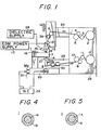
- FIG. 1 there is shown a TW-EDM apparatus incorporating the present invention.
- An electrode wire 1, typically of a thickness of 0.05 to 0.5 mm, dispensed from a supply reel 2 is guided to pass over a guide roller 3, between abutting rollers 4 and 5, over a guide roller 6, through a workpiece 7, over a guide roller 8, between abutting rollers 9 and 10 and over a roller 11 for takeup on to a takeup reel 12.
- the rollers 9 and 10 are driven by means of a motor (not shown) to axially transport the wire 1 from the supply reel 2 on to the takeup reel 12 through a cutting zone in the workpiece 7 between a pair of wire-positioning guide members 13 and 14.
- the rollers 4 and 5 may also be driven and serves as a brake to give a sufficient tension on the travelling wire 1 so that the wire 1 provides a straight travelling cutting electrode length in elec- troerosive machining relationship with the workpiece 7 across a machining gap between the positioning guide members 13 and 14.
- the machining gap is supplied with a flushing liquid medium, e.g. deionized water, from one or more nozzles 15 which communicates with a supply 28 of the pressurized flushing medium.
- the wire 1 is electrically connected via one or more conducting pins 16 to one terminal of an EDM power supply 17 whose other terminal is electrically connected via an electrically conductive clamp 18 to the workpiece 7.
- the EDM power supply 17 provides a succession of electrical voltage pulses which may result correspondingly in electrical discharges passed between the travelling wire 1 and the workpiece across the gap to electroerosively remove stock from the workpiece 7.
- the clamp 18 serves to secure the workpiece 7 to a stand 19 securely mounted on a worktable 20 which is in turn movably mounted on a base 21 of the EDM apparatus.
- the worktable 20 is driven by a pair of motors Mx, My under commands of a numerical control (NC) unit 29 to displace the workpiece 7 relative to the travelling wire 1 along a programmed path of feed in a horizontal plane to advance the erosive stock removal along that path, thereby forming a corresponding contour in the workpiece 7.
- NC numerical control
- the elements 2-5 and 9-12 are shown as mounted on a column 22 standing upright on the base 21.
- the elements 6, 13 and 16 are mounted on a tool head 23 which is carried on the end of an upper horizontal arm 24 which in turn extends from the column 22 and the elements 8 and 14 are mounted on the end of a lower horizontal arm 25 also extending from the column 22.
- Electrode-vibrating units 26 and 27, which may be of the type described in US Patent No. 4,321,450 and No. 4,358,655, are also shown associated with the wire-positioning guide members 13 and 14, respectively, for imparting high-frequency mechanical vibrations to the wire 1 travelling through the cutting zone.
- a magnetic detector 30 is provided downstream of the machining zone in the path of travel of the wire 1 for sensing a magnetic property of the wire 1 passed out of the machining zone, and is here shown as disposed between the guide roller 8 and the drive rollers 9, 10.
- a conventional non-magnetic or paramagnetic electrode wire such as a copper or base wire may be employed if the workpiece 7 is a ferromagnetic material such as a magnetic steel or a metal carbide cemented with cobalt. It has been found that when an eroding electrical discharge is effected between a point of the wire electrode and the workpiece, thus removing material from the latter, an amount of the removed workpiece material tends to deposit on that point of the wire. Thus, a uniform distribution of electrical discharges over the cutting zone results in a deposit of the magnetic material uniformly distributed on the,active wire electrode surface. Accordingly, a disturbance of the desired uniformity of the magnetic property over a length of the wire outgoing from the machining zone indicates a disturbance of the normal mode of electrical discharges in the machining zone.
- the magnetic detector 30 may comprise an annular coil 31 constructed and arranged coaxially with the wire 1 in a magnetic sensing relationship therewith.
- the detector 30 may also take a magnetic pick-up having a sensing coil and disposed in a magnetic sensing relationship with the wire 1.
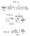
- the output of the sensing coil 31 is fed via an amplifier 32 to a detecting circuit 33 whose output is in turn connected to a counter 34.
- the detecting circuit 33 produces an output pulse each time the sensing coil 31 fails to detect magnetism during each increment of the displacement of the wire 1.
- pulses are consecutively produced from the detecting circuit 33.
- the control signal may be applied to the EDM power supply 17 to modify one or more of the discharge parameters such as the peak current lp, the duration T on and the pulse interval Toff of the discharge pulses, to the fluid supply 15a to increase the pressure and/or flow rate of the flushing medium into the machining zone, to the NC unit 29 to reduce the rate of machining feed, and/or to the electrode vibration units 26, 27 to initiate imparting high-frequency vibrations to the wire 1 travelling across the workpiece 7.
- the arrangement of Fig. 1 is shown to include an auxiliary unit 35 which is disposed immediately upstream of the magnetic detector 30 or between the cutting zone and the magnetic detector 30 in the path of wire travel.
- the auxiliary unit 35 is constituted by a magnetizing unit 40 as shown in Fig. 3.
- the magnetizing unit 40 shown comprises a magnetizing coil 41 surrounding the wire 1, a capacitor 42 connected with the coil 41 via a switch 43, and a DC source 44 connected with the capacitor 42 via charging impedances 45.
- the capacitor 42 is alternately charged from the DC source 44 and discharged through the coil 41 as the switch 43 is periodically turned on and off by an oscillator 46 to develop a succession of electrical pulses in the coil 41 and a corresponding pulsed magnetic field therethrough so that a deposit of the magnetic material from the workpiece 7 if present on the wire travelling through the coil 41 may be instantaneously magnetized to a full magnetization level.
- the wire which is already ferromagnetic prior to entry into the machining zone.
- the wire may be composed homogeneously of a ferrous material or steel or may, as shown in Fig. 4, be constituted by a steel or ferrous core wire 1a coated with a layer 1b of metal or alloy of a higher electrically conductivity such as copper, brass or aluminium.
- the wire 1 may, as shown in Fig. 5, be composed of a core wire 1c of such a metal or alloy coated with a layer 1 d of a magnetic material such as a ferrite or a mixture of the ferrite with the metal or alloy.
- the steel or ferrous material is preferably composed of a hard or piano wire steel, e.g. JIS3506-SWRH62A (Japanese Industrial Standard) or JIS3506-SWRH32A (Japanese Industrial Standard) but may also be of a high-carbon steel, a magnetic stainless steel, a chromium or chromium-molybdenum steel, an iron-manganese-titanium alloy or an iron-chromium-cobalt alloy. Since such a material is tough, the wire 1 can much be reduced in thickness.
- a hard or piano wire steel e.g. JIS3506-SWRH62A (Japanese Industrial Standard) or JIS3506-SWRH32A (Japanese Industrial Standard) but may also be of a high-carbon steel, a magnetic stainless steel, a chromium or chromium-molybdenum steel, an iron-manganese-titanium alloy or an iron-chromium-co
- wire 1 which has a strength far greater to withstand breakage and affords higher removal rate and machining stability, than the conventional TW-EDM wires, can be provided when the wire 1 or the core wire 1a is composed of a material containing 0.05 to 3% by weight one or more rare-earth elements such as yttrium, samarium, lanthanum or cerium or in the form a misch metal, and the balance a hard or piano steel, preferably the steel which consists by weight of 0.59 to 0.66% carbon, 0.15 to 0.35% silicon, 0.3 to 0.6% manganese, not greater than 0.04% phosphor, not greater than 0.04% sulfur and the balance iron, or the steel which consists by weight of 0.29 to 0.36% carbon, 0.15 to 0.35% silicon, 0.3 to 0.6% manganese, not greater than 0.04% phosphor, not greater than 0.04% sulfur and the balance iron.
- the wire 1 or the core wire 1a is composed of a material containing 0.05 to 3% by weight one
- the magnetic detector 30 disposed downstream of the cutting zone is capable of providing at the output of the counter 34 a signal representing a disturbance of electrical discharges from the normal mode in the cutting zone.
- the alternation of the magnetic property at a discharge-stricken zone of the wire is observed by the fact that each such zone is magnetically hardened.
- the wire 1 with such magnetically hardened zones may be passed through the magnetizing unit 35 and then into the magnetic detector 30 in the arrangement of Fig. 1.
- the magnetically hardened zones are magnetized to a full magnetization level to develop a greater magnetic flux to facilitate sensing by the magnetic pickup or the sensing coil 31.
- Fig. 1 The arrangement of Fig. 1 is also shown to include or further auxiliary assembly 36 disposed upstream of the cutting zone and which may include a demagnetizing unit 50.
- the demagnetizing unit 50 comprises a coil 51 surrounding the ferromagnetic wire 1 travelling into the cutting zone and a current supply for passing a damping AC through the coil 51.
- the demagnetizing unit 50 is provided to eliminate any magnetization which the wire 1 may have had as supplied with or stored on the reel 2 or as travelling through the supply side of the system in its path of travel, and thus to ensure that the wire 1 travelling into the cutting zone is uniform in the magnetic property over its length.
- the auxiliary magnetic assembly 36 may also include a magnetizing unit 40 as shown in and previously described in connection with, Fig. 3.
- the magnetizing unit 40 in this case is designed to regularly magnetize the ferromagnetic wire 1 travelling into the cutting zone. A series of small magnetic units, each with N and S poles, may be produced in the ferromagnetic wire 1 along its length. The regular distribution of these magnetic units tends to be altered as the wire 1 is passed through the cutting zone while being subjected to eroding electrical discharges. If a disturbance of the electrical discharges is created in the cutting zone, there results a length of the wire 1 in which the original distribution of the small magnetic units remains substantially unchanged.
- the magnetic detector 30 responds to the occurrence of such a length and provides a control signal which may be used to control one or more machining parameters so as to restore the normal mode in the machining zone, as previously described.
Landscapes
- Chemical & Material Sciences (AREA)
- Chemical Kinetics & Catalysis (AREA)
- Electrochemistry (AREA)
- Engineering & Computer Science (AREA)
- Mechanical Engineering (AREA)
- Electrical Discharge Machining, Electrochemical Machining, And Combined Machining (AREA)
Claims (22)
caractérisé en ce qu'il comprend des moyens (30) disposés en aval de la zone d'usinage sur le chemin prédéterminé de déplacement pour détecter une propriété magnétique de l'électrode (1) sortant de la zone d'usinage afin de produire un signal représentant une perturbation des décharges électriques dans cette zone d'usinage par rapport à un mode d'usinage prédéterminé.
Applications Claiming Priority (8)
| Application Number | Priority Date | Filing Date | Title |
|---|---|---|---|
| JP85110/83 | 1983-05-17 | ||
| JP8511083A JPS59211550A (ja) | 1983-05-17 | 1983-05-17 | ワイヤカツト放電加工用電極材 |
| JP129192/83 | 1983-07-14 | ||
| JP12919283A JPS6029222A (ja) | 1983-07-14 | 1983-07-14 | ワイヤカット放電加工方法及び装置 |
| JP13164383A JPS6029223A (ja) | 1983-07-18 | 1983-07-18 | ワイヤカット放電加工方法及び装置 |
| JP131643/83 | 1983-07-18 | ||
| JP149226/83 | 1983-08-17 | ||
| JP14922683A JPS6044230A (ja) | 1983-08-17 | 1983-08-17 | ワイヤカット放電加工方法及び装置 |
Publications (2)
| Publication Number | Publication Date |
|---|---|
| EP0129334A1 EP0129334A1 (fr) | 1984-12-27 |
| EP0129334B1 true EP0129334B1 (fr) | 1987-07-15 |
Family
ID=27467057
Family Applications (1)
| Application Number | Title | Priority Date | Filing Date |
|---|---|---|---|
| EP84303355A Expired EP0129334B1 (fr) | 1983-05-17 | 1984-05-17 | Procédé d'usinage par décharges électriques à fil mobile et appareil avec une électrode à fil ferromagnétique |
Country Status (3)
| Country | Link |
|---|---|
| US (2) | US4609803A (fr) |
| EP (1) | EP0129334B1 (fr) |
| DE (2) | DE129334T1 (fr) |
Families Citing this family (14)
| Publication number | Priority date | Publication date | Assignee | Title |
|---|---|---|---|---|
| JPS62148121A (ja) * | 1985-12-20 | 1987-07-02 | Sumitomo Electric Ind Ltd | 放電加工用カツトワイヤ |
| JPS62188624A (ja) * | 1986-02-13 | 1987-08-18 | Res Dev Corp Of Japan | 金属工作物の加工面の仕上げ方法及びその装置 |
| KR930004834B1 (ko) * | 1988-05-18 | 1993-06-09 | 미쯔비시덴끼 가부시끼가이샤 | 와이어커트 방전가공장치의 와이어전극 공급장치 |
| CH684882A5 (fr) * | 1991-05-31 | 1995-01-31 | Charmilles Technologies | Machine d'électroérosion à fil avec guide-fil mobiles dans deux plans horizontaux. |
| ES1027059Y (es) * | 1994-02-15 | 1995-01-16 | Ona Electro Erosion | Dispositivo de enhebrado automatico para maquina de electroerosion por hilo. |
| DE10000858A1 (de) * | 2000-01-12 | 2001-07-26 | Berkenhoff Gmbh | Drahtelektrode für das funkenerosive Schneiden von Hartmetall |
| DE10061691B4 (de) | 2000-12-12 | 2004-12-30 | Agie S.A., Losone | Vorrichtung und Verfahren zur Detektion einer Bearbeitungselektrode einer Werkzeugmaschine |
| JP4788861B2 (ja) * | 2003-11-28 | 2011-10-05 | ヤマハ株式会社 | 楽器弦用鋼線およびその製造方法 |
| US7824533B2 (en) * | 2004-10-25 | 2010-11-02 | Industrial Door Co., Inc. | Tempered plated wire and methods of manufacture |
| US7906743B2 (en) * | 2008-07-09 | 2011-03-15 | National Taipei University Of Technology | Gradation twin-wire EDM manufacturing system |
| US20100140226A1 (en) * | 2008-12-08 | 2010-06-10 | Dong-Yea Sheu | Tandem micro electro-discharge machining apparatus |
| CN102873414B (zh) * | 2012-10-30 | 2015-12-09 | 安徽白兔湖动力有限公司 | 曲轴加工断钻头处理电火花机床 |
| CN110524070A (zh) * | 2019-08-16 | 2019-12-03 | 山东大学 | 一种工具电极结构及电火花加工装置 |
| CN110524073A (zh) * | 2019-08-16 | 2019-12-03 | 山东大学 | 一种线切割结构、方法及电火花线切割装置 |
Family Cites Families (20)
| Publication number | Priority date | Publication date | Assignee | Title |
|---|---|---|---|---|
| GB871127A (en) * | 1958-11-06 | 1961-06-21 | Molybdenum Corp | Method for the production of iron or steel alloys |
| JPS4946754B2 (fr) * | 1971-07-29 | 1974-12-11 | ||
| JPS5950457B2 (ja) * | 1975-11-07 | 1984-12-08 | 株式会社井上ジャパックス研究所 | ホウデンカコウソウチ |
| JPS597771B2 (ja) * | 1976-10-18 | 1984-02-21 | 株式会社井上ジャパックス研究所 | ワイヤカツト放電加工用電極材料 |
| JPS53100119A (en) * | 1977-02-14 | 1978-09-01 | Kawasaki Steel Co | Low alloy steel providing electric resistance welding part with good groove corrosion resistance |
| GB2015909B (en) * | 1978-03-03 | 1982-12-01 | Charmilles Sa Ateliers | Electrode for spark erosion machining |
| JPS55106736A (en) * | 1979-02-13 | 1980-08-15 | Fanuc Ltd | Wire cut spark erosion machine |
| JPS55125940A (en) * | 1979-03-23 | 1980-09-29 | Mitsubishi Electric Corp | Electrical discharge machine of worked piece consisting of magnetic substance |
| SE444278B (sv) * | 1979-10-11 | 1986-04-07 | Charmilles Sa Ateliers | Tradformig elektrod samt sett att tillverka sadan elektrod |
| SU863264A1 (ru) * | 1979-12-06 | 1981-09-15 | Предприятие П/Я Р-6209 | Состав сварочной проволоки |
| JPS56119323A (en) * | 1980-02-18 | 1981-09-18 | Inoue Japax Res Inc | Wire cutting electric discharge machining apparatus |
| JPS56126533A (en) * | 1980-03-07 | 1981-10-03 | Inoue Japax Res Inc | Wire cut spark machining device |
| JPS5785947A (en) * | 1980-11-14 | 1982-05-28 | Furukawa Electric Co Ltd:The | Electrode wire for wire-cut electric spark machining |
| JPS57149120A (en) * | 1981-03-13 | 1982-09-14 | Inoue Japax Res Inc | Vibration preventive device of wire electrode in wire cut electric discharge machining |
| JPS57156129A (en) * | 1981-03-17 | 1982-09-27 | Furukawa Electric Co Ltd:The | Wire cut electric discharge machining electrode wire |
| JPS5828432A (ja) * | 1981-08-12 | 1983-02-19 | Inoue Japax Res Inc | ワイヤカツト放電加工装置 |
| JPS5828430A (ja) * | 1981-08-12 | 1983-02-19 | Inoue Japax Res Inc | ワイヤカツト放電加工方法 |
| JPS5877552A (ja) * | 1981-10-30 | 1983-05-10 | Kawasaki Steel Corp | 耐塩性鉄筋コンクリ−ト用棒鋼 |
| JPS5980752A (ja) * | 1982-10-28 | 1984-05-10 | Nippon Kokan Kk <Nkk> | 硫化水素環境で溶接部の耐水素割れ性及び耐硫化物応力腐食割れ性に優れた鋼 |
| JPS60174849A (ja) * | 1984-02-20 | 1985-09-09 | Nippon Steel Corp | 耐粒界割れ応力腐食割れ性に優れた構造用材料 |
-
1984
- 1984-05-17 EP EP84303355A patent/EP0129334B1/fr not_active Expired
- 1984-05-17 US US06/611,406 patent/US4609803A/en not_active Expired - Lifetime
- 1984-05-17 DE DE198484303355T patent/DE129334T1/de active Pending
- 1984-05-17 DE DE8484303355T patent/DE3464708D1/de not_active Expired
-
1986
- 1986-08-19 US US06/898,035 patent/US4777337A/en not_active Expired - Lifetime
Also Published As
| Publication number | Publication date |
|---|---|
| DE3464708D1 (en) | 1987-09-17 |
| US4609803A (en) | 1986-09-02 |
| EP0129334A1 (fr) | 1984-12-27 |
| US4777337A (en) | 1988-10-11 |
| DE129334T1 (de) | 1987-08-13 |
Similar Documents
| Publication | Publication Date | Title |
|---|---|---|
| US4777337A (en) | TW-EDM method and apparatus with a ferromagnetic wire electrode | |
| Kinoshita et al. | Control of wire-EDM preventing electrode from breaking | |
| US4052583A (en) | Method of and apparatus for electrical-discharge machining with a traveling-wire electrode | |
| US5828027A (en) | Electrical discharge machine with tar build-up detector | |
| US4504721A (en) | 3D EDM method and apparatus utilizing a magnetic field | |
| CN1144643C (zh) | 使用线电极电火花腐蚀的精加工方法及其电火花腐蚀加工机 | |
| GB2069396A (en) | Wire-cutting electroerosion machining method and apparatus | |
| EP1533065B1 (fr) | Dispositif de decharge electrique a fil | |
| US4471197A (en) | Method of and arrangement for preventing uncontrolled oscillations of electrode wire in electroerosion machining apparatus | |
| US4379960A (en) | Electrical discharge machining method and apparatus using ultrasonic waves and magnetic energy applied concurrently to the machining gap | |
| US4510366A (en) | Fluid delivery rate control TW electrical machining method and apparatus | |
| US4495038A (en) | Method of and apparatus for electroerosively wire-cutting a conductive workpiece | |
| EP0554899B1 (fr) | Machine d'électroérosion avec électrode secondaire pour la prévention de la corrosion | |
| US4607149A (en) | Fluid delivery rate control tw electrical machining method and apparatus | |
| US4513192A (en) | TW-EDM Method and apparatus with excess fluid stripping gas jet nozzle | |
| EP0526089B1 (fr) | Appareil d'usinage par électroérosion | |
| GB2082954A (en) | Wire-cutting electroerosion machining method and apparatus | |
| JP2626666B2 (ja) | 放電加工方法 | |
| GB2045671A (en) | Stabilising travelling-wire electrode position in electrical discharge machining process | |
| US4608143A (en) | TW-electroerosion apparatus with wheeled drive carriages | |
| JPH0543446B2 (fr) | ||
| JPS59102529A (ja) | ワイヤカツト放電加工装置 | |
| US4366358A (en) | EDM Method and apparatus utilizing successively displaced magnetic field | |
| JPS6044230A (ja) | ワイヤカット放電加工方法及び装置 | |
| JPS582011B2 (ja) | ワイヤ−カツトホウデンカコウソウチ |
Legal Events
| Date | Code | Title | Description |
|---|---|---|---|
| PUAI | Public reference made under article 153(3) epc to a published international application that has entered the european phase |
Free format text: ORIGINAL CODE: 0009012 |
|
| AK | Designated contracting states |
Designated state(s): AT BE CH DE FR GB IT LI LU NL SE |
|
| 17P | Request for examination filed |
Effective date: 19841129 |
|
| RBV | Designated contracting states (corrected) |
Designated state(s): DE FR GB IT |
|
| ITCL | It: translation for ep claims filed |
Representative=s name: FIAMMENGHI FIAMMENGHI RACHELI |
|
| EL | Fr: translation of claims filed | ||
| 17Q | First examination report despatched |
Effective date: 19860305 |
|
| ITF | It: translation for a ep patent filed | ||
| GRAA | (expected) grant |
Free format text: ORIGINAL CODE: 0009210 |
|
| AK | Designated contracting states |
Kind code of ref document: B1 Designated state(s): DE FR GB IT |
|
| DET | De: translation of patent claims | ||
| REF | Corresponds to: |
Ref document number: 3464708 Country of ref document: DE Date of ref document: 19870917 |
|
| ET | Fr: translation filed | ||
| PLBE | No opposition filed within time limit |
Free format text: ORIGINAL CODE: 0009261 |
|
| STAA | Information on the status of an ep patent application or granted ep patent |
Free format text: STATUS: NO OPPOSITION FILED WITHIN TIME LIMIT |
|
| 26N | No opposition filed | ||
| PGFP | Annual fee paid to national office [announced via postgrant information from national office to epo] |
Ref country code: FR Payment date: 19900427 Year of fee payment: 7 |
|
| ITTA | It: last paid annual fee | ||
| PG25 | Lapsed in a contracting state [announced via postgrant information from national office to epo] |
Ref country code: FR Effective date: 19920131 |
|
| REG | Reference to a national code |
Ref country code: FR Ref legal event code: ST |
|
| PGFP | Annual fee paid to national office [announced via postgrant information from national office to epo] |
Ref country code: GB Payment date: 19990423 Year of fee payment: 16 |
|
| PGFP | Annual fee paid to national office [announced via postgrant information from national office to epo] |
Ref country code: DE Payment date: 19990526 Year of fee payment: 16 |
|
| PG25 | Lapsed in a contracting state [announced via postgrant information from national office to epo] |
Ref country code: GB Free format text: LAPSE BECAUSE OF NON-PAYMENT OF DUE FEES Effective date: 20000517 |
|
| GBPC | Gb: european patent ceased through non-payment of renewal fee |
Effective date: 20000517 |
|
| PG25 | Lapsed in a contracting state [announced via postgrant information from national office to epo] |
Ref country code: DE Free format text: LAPSE BECAUSE OF NON-PAYMENT OF DUE FEES Effective date: 20010301 |