EP0129340A1 - Elektrische Funkenerosionsvorrichtung zur Herstellung von Feinbohrungen - Google Patents
Elektrische Funkenerosionsvorrichtung zur Herstellung von Feinbohrungen Download PDFInfo
- Publication number
- EP0129340A1 EP0129340A1 EP84303406A EP84303406A EP0129340A1 EP 0129340 A1 EP0129340 A1 EP 0129340A1 EP 84303406 A EP84303406 A EP 84303406A EP 84303406 A EP84303406 A EP 84303406A EP 0129340 A1 EP0129340 A1 EP 0129340A1
- Authority
- EP
- European Patent Office
- Prior art keywords
- workpiece
- machining
- electrode
- electrical discharge
- discharge machining
- Prior art date
- Legal status (The legal status is an assumption and is not a legal conclusion. Google has not performed a legal analysis and makes no representation as to the accuracy of the status listed.)
- Granted
Links
Images


Classifications
-
- B—PERFORMING OPERATIONS; TRANSPORTING
- B23—MACHINE TOOLS; METAL-WORKING NOT OTHERWISE PROVIDED FOR
- B23H—WORKING OF METAL BY THE ACTION OF A HIGH CONCENTRATION OF ELECTRIC CURRENT ON A WORKPIECE USING AN ELECTRODE WHICH TAKES THE PLACE OF A TOOL; SUCH WORKING COMBINED WITH OTHER FORMS OF WORKING OF METAL
- B23H9/00—Machining specially adapted for treating particular metal objects or for obtaining special effects or results on metal objects
- B23H9/14—Making holes
-
- B—PERFORMING OPERATIONS; TRANSPORTING
- B23—MACHINE TOOLS; METAL-WORKING NOT OTHERWISE PROVIDED FOR
- B23H—WORKING OF METAL BY THE ACTION OF A HIGH CONCENTRATION OF ELECTRIC CURRENT ON A WORKPIECE USING AN ELECTRODE WHICH TAKES THE PLACE OF A TOOL; SUCH WORKING COMBINED WITH OTHER FORMS OF WORKING OF METAL
- B23H7/00—Processes or apparatus applicable to both electrical discharge machining and electrochemical machining
- B23H7/26—Apparatus for moving or positioning electrode relatively to workpiece; Mounting of electrode
- B23H7/265—Mounting of one or more thin electrodes
-
- B—PERFORMING OPERATIONS; TRANSPORTING
- B23—MACHINE TOOLS; METAL-WORKING NOT OTHERWISE PROVIDED FOR
- B23Q—DETAILS, COMPONENTS, OR ACCESSORIES FOR MACHINE TOOLS, e.g. ARRANGEMENTS FOR COPYING OR CONTROLLING; MACHINE TOOLS IN GENERAL CHARACTERISED BY THE CONSTRUCTION OF PARTICULAR DETAILS OR COMPONENTS; COMBINATIONS OR ASSOCIATIONS OF METAL-WORKING MACHINES, NOT DIRECTED TO A PARTICULAR RESULT
- B23Q17/00—Arrangements for observing, indicating or measuring on machine tools
- B23Q17/24—Arrangements for observing, indicating or measuring on machine tools using optics or electromagnetic waves
Definitions
- the present invention relates to an apparatus for forming minute holes in a workpiece through an electrical discharge machining (EDM) or electroerosive machining process.
- EDM electrical discharge machining
- EDM Electrical discharge machining
- EDM machining processes for forming a minute hole having a diameter of 0.1 mm or smaller in a workpiece.
- the machining electrode is held at rest, and in the other process, the machining electrode is rotated about its own axis. Rotating the machining electrode could increase the machining speed, and improve out-of-roundness and accuracy of the shape of the hole formed.
- the machining process in which the electrode is held at rest during operation has heretofore been prevalent in the art since the electrode is not subjected to displacement and the time required for the electrode to form the hole is shorter.
- Electrodes are known for use in forming holes while the electrode is held at rest. Where a thin wire which requires no cutting is employed as an electrode, it is directly soldered to an electrode holder, or is plated, reinforced, and chucked, or protected and guided by a body of glass, ruby or the like and chucked. Where a relatively thick wire is used for an electrode, the tip end thereof is thinned by electrolytic grinding so as to serve as a machining electrode.
- the above electrode constructions however fail to provide a degree of concentricity of a few microns or less between the machining tip and outer periphery of the electrode. It has been impossible to use such electrode in machining a hole while rotating the electrode since it is difficult to attach the electrode perpendicularly to the workpiece.
- One electrode construction used for machining a workpiece while the electrode is rotating is composed of a round rod having a diameter of about 1 mm which can be chucked.
- the electrode material as it is rotated is shaped into an electrode of a desired diameter by a reverse electrical discharge. Although the electrode thus formed has sufficient accuracy, it will take about one hour to form an electrode for forming a minute hole 30 micrometers across from an electrode material having a diameter of 1 mm.
- the thined portion of the electrode which has a diameter of 30 micrometers is short in length and hence in service life. Because the electrode will be displaced once detached from the chuck, the electrode has to be formed again each time it machines a minute hole in a workpiece.
- EDM machines employ a ball-and-roller bearing by which the electrode is rotatably supported.
- the ball-and-roller bearing however cannot avoid displacements of the electrode by a few micrometers.
- the electrode assembly comprises a spindle construction as a whole which has a large stray capacity and hence cannot reduce the capacitance of an RC circuit. Where holes having a diameter of about 50 micrometers are formed by such an electrode assembly, accuracies such as out-of-roundness and surface roughness become extremely poor.
- the electrode assembly is heavy and its speed of response for feeding the electrode is necessarily reduced. Therefore, the electrode assembly has no smooth machining capability, and can machine holes in a practical range of diameters down to about 100 micrometers at minimum.
- Another problem with the prior EDM machines is that it is quite a complex task to position the electrode accurately for forming a minute hole.
- Two processes have been available for positioning the machining elecrode and workpiece with respect to each other in forming a hole having a diameter of 0.3 mm or smaller.
- One positioning process is known as a contact sensing process in which an electric short circuit is sensed between the machining electrode and the workpiece, a contact position is read on a position scale or the like, and the electrode and the workpiece are relatively moved to a desired position according to the reading on the position scale.
- a weak voltage is applied between a machining electrode and a workpiece placed in an insulative liquid contained in a machining bath on an X-Y table, while at the same time the machining electrode is moved horizontally toward the workpiece.
- a short-circuiting current flowing between the machining electrode and the workpiece is detected and the reading on the position scale at this time is set as 0.
- the X-Y table is moved a distance a + d/2 in the direction of X taking the diameter d of the machining electrode into account, so that the central axis of the machining electrode will be in registration with the desired position.
- the center of the machining electrode is brought accurately into registration with another position in which to pierce another hole.
- the above process can provide a sufficient degree of accuracy where the machining electrode has a relatively large diameter.
- the machining electrode has a diameter of a few tens micrometers for forming minute holes, the electrode lacks desired rigidity and tends to flex upon contact with the workpiece, resulting in the failure of accurate positioning.
- Another positioning process uses a stereomicroscope for observing the tip of the machining electrode and the workpiece while positioning them relatively to each other. This positioning process however also fails to effect accurate positioning because of the parallax since the workpiece is obliquely observed.
- Another object of the present invention is to provide an electrical discharge machining apparatus for forming minute holes in a workpiece, which requires no spindle construction, has a light and small-size electrode assembly, has an electrode support electrically insulated from the other parts for greatly reducing a stray capacity, and hence is capable of forming minute holes of small surface roughness and out-of-roundness and diameters ranging from 10 to 200 micrometers at high machining speeds.
- Still another object of the present invention is to provide an electrical discharge machining apparatus for forming minute holes in a workpiece, which presents no parallax and can position a thin machining electrode relatively to a workpiece with high accuracy.
- Still another object of the present invention is to provide an electrical discharge machining apparatus for forming minute holes in a workpiece, which has a support tube supporting an electrode core wire and a rotatable support body, the support tube and the rotatable support body having a central axis and a center of rotation which are aligned with each other highly accurately for preventing the electrode from wobbling movement or displacement during rotation thereof, so that minute holes of small out-of-roundness and good accuracy of shape can be formed in a workpiece.
- a still further object of the present invention is to provide an electrical discharge machining electrode for forming minute holes, which can be fed out of a rotatable support body as the electrode is progressively consumed by electrical discharges, so that the electrode can be used for a long period of time.
- a still further object of the present invention is to provide an electrical discharge machining electrode for forming minute holes, which can easily be manufacured from a commercially available thin core wire.
- a still further object of the present invention is to provide an electrical discharge machining electrode for forming minute holes, which allows easy removal of machined chips produced upon electrical discharge machining for an increased machining speed.
- an electrical discharge machining apparatus for forming a minute hole in a workpiece, comprising a machining electrode for forming the minute hole in the workpiece by an electrical discharge between the machining electrode and the workpiece, a machining electrode moving means for moving the machining electrode toward and away from the workpiece, a positioning means for establishing a machining position with respect to the workpiece, and a workpiece moving means for moving the workpiece between a first position below the machining electrode and a second position below the positioning means.
- the machining electrode is composed of an electrode core wire slidably supported in a support tube having an outer periphery and a bore in which the electrode core wire is inserted, the outer periphery and the hole being in highly concentric relation to each other.
- the support tube is coupled to a rotatable support body by which rotative power is transmitted to the support tube, with their axes of rotation in alignment with each other.
- the machining electrode is supported by a support means having V-shaped grooves and will be rotated at a constant speed while an electrical discharge is produced between the machining electrode and the workpiece.
- the machining position can be established by piercing a minute hole in the workpiece at any desired position, moving the workpiece to the position below the positioning means to bring the pierced minute hole into alignment with a prescribed position in the field of view of a microscope so that the positions directly below the machining electrode and the microscope will be in conjugate relationship, then setting a position in which to machine the workpiece at the prescribed position in the field of view of the microscope, and thereafter returning the workpiece to the position directly below the machining electrode.
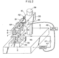
- the electrical discharge machining apparatus includes a mac ining electrode 4 and a machining head 10 supporting the machining electrode 4.
- a workpiece 1 is placed on a support base 11 disposed in a machining bath 2.
- L ng electrode 4 is moved toward the workpiece 1 while rotating the machining electrode 4, an electrical discharge is initiated between the machining electrode 4 and the workpiece 1.
- a minute hole can be formed in the workpiece I by successively feeding the machining electrode 4 toward the workpiece 1.
- the EDM apparatus also includes a positioning microscope 12 movable in three directions, that is, X and Y directions extending parallel to a base 3 and perpendicularly to each other, and a Z direction extending perpendicularly to the base 3 and the X and Y directions.
- the machining bath 2 can be fed in the X direction by sliding a slide plate 29 of the bath 2 on a slide table 14 with a fine adjustment screw 13.
- the machining bath 2 can be angularly adjusted in an X-Y plane with a fine adjustment screw 27.
- the slide table 14 can be moved in the X direction until it abuts against stoppers 31, 32.
- stoppers 31, 32 When the slide plate 14 is fixed in abutment against the stopper 31, the workpiece 1 is positioned directly below the machining electrode 4.
- the slide plate 14 is fixed in abutment against the stopper 32, the workpiece 1 is positioned directly below the microscope 12.
- An eccentric cam 33 is angularly movable by a lever 34 as described later on.
- a table 17 movable in the Y direction is disposed beneath the slide table 14 and can be moved by a feed screw 18.
- the machining bath 2, the slide table 14, and the table 17 jointly constitute a support base assembly.
- the machining head 10, the microscope 12, and the support base assembly are mounted individually on the base 3.
- the microscope 12 is mounted on a holder having a slide mechanism having three slides. More specifically, a slide 21a extends in a driection perpendicular to the workpiece I or the Z direction for adjusting the focus of the microscope 12.
- the slide 21a can be replaced with a mechanism for moving an objective lens of the microscope upwardly and downwardly.
- a slide 21b serves to move the microscope 12 in the same direction as that of movement of the slide table 14, or the X direction.
- a slide 21c serves to move the microscope 12 in a direction, or the Y direction, normal to the direction in which the slide table 14 moves.
- the microscope 12 has an eyepiece bearing cross hairs 15 which will appear in the field of view of the viewer, the intersection of the cross hairs 15 serving as a sight.
- FIG. 2 shows the machining head 10 in greater detail.
- the machining electrode 4 is rotatably supported by a support or bearing 6 having V-shaped grooves, and will be rotated by a belt 5 trained around a pulley 7 on the machining electrode 4 and a pulley 9 on a motor 8, while at the same time the machining electrode 4 is held against the bearing 6. Since the pully 9 is located upwardly of the pulley 7, the machining electrode 4 is biased to move upwardly under the tension of the belt 5 while being rotated by the motor 8.
- the machining electrode 4, the bearing 6, and the pulley 7 jointly constitute an electrode assembly electrically insulated by an insulator 16 as of ceramics from a body 35 of the machining head 10.
- the electrode assembly is electrically connected to a DC power supply 37 by means of a brush 36.
- the machining electrode 4 can be fed selectively in two modes, that is, rough feeding and fine feeding.
- the body 35 is vertically slid along a post 38 on the base 3 to bring the machining electrode 4 together with the body 35 to a position near the workpiece I disposed in the machining bath 12.
- a pinion gear 42 is rotated by a motor 43 to rotate a gear 19a integral with a feed screw 19 for thereby vertically moving the feed screw 19, causing a pivot lever 44 to move the machining electrode 4 for a small vertical interval.
- a machining circuit is composed of the DC power supply 37, a capacitor 45, and a resistor 36 through which the brush 36 is connected to the DC power supply 37.
- a machining current flowing through the machining circuit is detected by a current monitor 47 and utilized for enabling a servo control circuit 47 to control the speed and direction of rotation of the motor 43 for controlling the speed and direction of fine feeding movement of the machining electrode 4.
- the motor 43 is rotated counterclockwise at a prescribed constant speed to feed the machining electrode 4 at a predetermined speed toward the workpiece 1.
- the current monitor 47 detects a short-circuiting current and causes the servo control circuit 48 to rotate the motor 43 clockwise at a high speed for moving the machining electrode 4 away from the workpiece 1 at a high speed.
- the motor 43 is rotated counterclockwise again to feed the machining electrode 4 at the prescribed speed toward the workpiece 1.
- the workpiece 1 is progressively machined while the above cycle of operation is repeated.
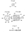
- FIGS. 3 through 5 illustrate the machining electrode 4.
- the machining electrode 4 is constructed of a thin electrode core wire 51 slidably guided in a wire guide or support tube 52 made of ceramics which is attached by a guide sleeve or tube 54 to a metal mandrel or rotatable support body 53.
- the wire 51 has an end connected to a pipe 56 made of an electrically conductive material and fixedly mounted in the mandrel 53 by means of a metal screw 55.
- the wire guide 52 is fitted in the guide sleeve 54 with a clearance of 2 micrometers or smaller therebetween.
- the mandrel 53 is fitted in the guide sleeve 54 with a clearance as defined in JIS (Japanese Industrial Standards) h6 - P6.
- the wire guide 52 comprises a ceramic pipe for use as an optical fiber connector core, and the electrode core wire 51 is fitted therein with a clearance of 1 micrometer or less.
- the wire guide 52 has an outer peripheral surface and a bore which are concentric with each other with an error of 1 micrometer or less.
- the bore of the guide sleeve 54 is finished by lapping so that the inside diameter thereof differs from the outside diameter of the wire guide 52 by the range of 0 to 2 micrometers.
- the mandrel 53 is disposed in the guide sleeve 54 with a close fit having a clearance as defined in JIS h6 - P6. Since the wire guide 52 is supported by the guide sleeve 54 with the outer peripheral surface of the mandrel 53 serving as a positioning reference, the machining electrode 4 is of high accuracy with the wire 51 displaceable to 4 micrometers at maximum.
- FIGS. 6A and 6B show a die used in vacuum extrusion molding.
- the die is composed of an outlet piece 57, a pin 58, and a pin holder 59 in which an end of the pin 58 is embedded.
- a kneaded mass 60 of ceramics is fed in the direction of the arrows to the right (as shown in FIG. 6B) through gaps 59' in the pin holder 59 into the outlet piece 57.
- the neaded ceramic mass 60 is then extruded out of the die in the form of a pipe by means of the pin 58 and the outlet piece 57.
- the error of concentricity between the bore and outer peripheral surface of the extruded ceramic pipe becomes 10 micrometers or smaller.
- a wire is threadd through the bore of the ceramic pipe and the outer peripheral surface is cylindrically ground by a centerless grinder with the wire serving as a guide, thus producing a high-precision wire guide 52 having a concentricity error of 3 micrometers or smaller.
- the guide sleeve 54 may be machined by various processes such as lapping or honing since only the bore in the guide sleeve 54 in which the wire guide 52 is fitted should meet the prescribed dimensional tolerance. It is easy to keep the dimensions of the guide sleeve 54 within the tolerance ranging from 0 to 2 micrometers.
- a fit as prescribed by JIS h6 - P6 can easily be achieved between the mandrel 53 and the guide sleeve 54 simply by grinding the outer peripheral surface fo the guide sleeve 54 with a cylindrical grinding machine.
- a pipe 56 is staked or soldered or otherwise connected to a rear end of the wire 51, as shown in FIG. 7, and then is secured to the mandrel 53 by a metal setscrew 55, as illustrated in FIG. 4.
- the wire guide 52 is fitted in the mandrel 53 with a clearance as prescribed by JIS h6 - H7.
- the wire guide 52 may be made of ruby, sintered metal, cemented carbide, for example, other than ceramics.
- the pipe 56 may be made of any electrically condictuve mateirals.
- the guide sleeve 54 may also be made of ruby, sintered metal, ordinary metal, for example, other than ceramics. According to the present embodiment, the clearance between the wire 51 and the wire guide 52 is on the order of 1 micron and hence is negligible.
- FIGS. 8A, 8B, and 8C illustrate the bearing 6 in detail.
- the bearing 6 is composed of two upper and lower V-grooved members 61 attached to a support body 62 and having V-shaped grooves or notches in which the machining electrode 4 is disposed and held against the V-grooved members 61.
- the V-grooved members 61 are made of ruby in the illustrated embodiment, but may also be made of hard metal, sapphire, diamond, quenched steel, or other wear-resistant materials.
- the V-grooved members 61 and the support body 62 may be of an integral construction of the same material.
- Each of the V-shaped grooves should preferably flare at an angle rangeing from 30° to 150°.
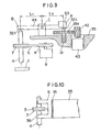
- FIG. 9 illustrates the fine feed mechanism in greater detail.
- the lever 44 is pivotally supported by a pivot C.
- the machining electrode 4 and the feed screw 19 have semispherial or conical ends held pivotally against contact members 321 on the lever 44 which are made of a highly wear-resistant material.
- the contact members 321 are in the form of sapphire blocks in the illustrated embodiment, but may be made of ruby, diamond, ultra high strength steel, or quenched steel, for example.
- the feed screw 19 has an externally threaded lower portion threaded in an internally threaded hole in the body 35. Upon rotation of the motor 43, the pinion 42 and the gear 19a meshing therewith are rotated to cause the feed screw 19 to move vertically as the gear 19a meshingly engages the pinion 42 at different positions. The vertical movement of the feed screw 19 is transmitted through the lever 44 to the machining electrode 4 which is then fed in its axial direction.
- the feed gear 19a and the pinion 42 have a gear ratio of 5 : 1
- the external threads on the feed screw 19 comprise righthand screw threads having a pitch of 0.5 mm
- the pinion 42 has a teeth length of 10 mm.
- the machining electrode 4 is operatively connected to the motor 8 by the pulleys 7, 9 and the belt 5. Since the machining electrode 4 is normally biased upwardly by the belt 5, the machining electrode 4 is held in contact with the lever 44 at all times. Accordingly, the vertical displacement of the lever end A is equal to the distance the machining electrode 4 is fed vertically. The foregoing mode of operation is effected when a stable electrical discharge is produced. When the workpiece 1 and the machining electrode 4 are short-circuited, the motor 43 is rotated clockwise to lift the machining electrode 4 off the workpiece 1. The tension of the belt 5 can be reduced by a weight 63 attached to the end A of the lever 44.
- FIG. 10 shows the manner in which the bearing 6 is electrically insulated for reducing any stray capacity and the brush 36 is in contact with the machining electrode 4.
- the body 35, and the machining electrode 4 and the bearing 6 are electrically insulated by the insulator 16 which is made of ceramics, paper, vinyl, or glass, for example.
- the machining electrode 4 and the machining power supply are held in electric contact directly by means of the brush 36. This arrangement allows the discharge circuit small in size to reduce any stray capacity which would influence electrical discharge machining.
- the machining bath 2 and the slide table 14 are illustrated in greater detail in FIG. 11.
- a rotatable slide 26 is mounted on the underside of the machining bath 2 and has a cylindrical portion slidably fitted in a hole 25 defined in an upper surface of the slide table 14.
- the machining bath 2 is angularly moved through a small angle about its center through the slidable fitting engagement between the slide 26 and the slide table 14.
- a ball bearing may be disposed between the slide 26 and the slide table 14 instead of fitting engagement therebetween.
- the machining bath 2 is movable in the direction of the arrow A (corresponding to the X direction in FIG. I) by the slide plate 29 attached to the underside of the machining bath 2 and guided by a guide 29a on the slide 26. The distance that the machining bath 2 is moved in the A direction can be adjusted by a feed screw 30.
- FIG. 12 shows the stoppers 31, 32 for the slide table 14.
- the stopper 31 disposed on the lefthand side (as shown) of the slide table 14 comprises a micrometer head, while the stopper 32 on the lefthand side of the slide table 14 comprises a permanent magnet having a ground end surface.
- the slide table 14 can be positioned at a lefthand limit position by pressing a lefthand end 14a of the slide table 14 against the micrometer-head stopper 31 with a spring (not shown) disposed within the slide table 14, and at a righthand limit position by magnetically attracting a righthand end 14b of the slide table 14 to the end surface of the magnetic stopper 32.
- the slide table 14 which has been attracted to the magnetic stopper 32 can be disenaged therefrom in one operation by angularly moving the eccentric cam 33 with the lever 34.
- the released slide table 14 is then pressed at its lefthand end 14a against the micrometer-head stopper 31 under the tension of the spring in the slide table 14, whereupon the machining electrode 4 of the machining head 10 is held in confronting relation to the workpiece 1 in the machining bath 2.
- the workpice 1 is placed in the machining bath 2 filled with an insulative machining solution such as illuminating kerosene.
- the workpiece 1 may roughly be positioned at this time.
- the slide table 14 is moved into abutment against the lefthand stopper 31 and stopped.
- the workpiece I is now positioned substantially below the machining electrode 4.
- the machining electrode 4 is rotated and lowered against the workpiece I to form a marking hole in the workpiece 1.
- the marking hole may be of a size which can be visually recognized.
- the machinung electrode 4 is raised, and the slide table 14 is moved into abutting engagement with the righthand stopper 32 and stopped there under magnetic forces of the stopper 32.
- the workpiece 1 is disposed substantially below the microscope 12.
- the microscope 12 is then moved by the slides 21a, 21b, 21c attached to the holder 20 for focusing adjustment until the crossing point, serving as the sight, of the cross hairs 15 in the field of view of the microscope 12 is aligned with the center of the marking hole in the workpiece 1.
- the position H (FIG. 1) of the machining electrode 4 and the crossing point I of the cross hairs 15 of the microscope 12 are brought into a conjugate relationship through the movement of the slide table 14.
- conjugate relationship means the condition in which when the slide table 14 is moved into engagement with the stoppers 31, 32, a desired position on the workpiece 1 in which to form a hole and which is established by the crossing point I of the cross hairs 15 under the microscope 12 coincides with the position of the hole which will actually be formed by the machining electrode 4 at all times. Accordingly, once such a congugate relationship is established, any desired position on the workpiece 1 which is to be perforated will be positioned directly below the machining electrode 4 by first bringing such a desired position on the workpiece 1 into alignment with the crossing point I of the cross hairs 15 under the microscope 12 and then moving the slide table 14 into abutment against the stopper 31 and stopping the slide table 14 there.
- the slide table 14 is fixed in abutment against the stopper 32. Then, the workpiece 1 is moved by sliding the slide 14 in the Y direction and the slide 29 in the X direction with the feed screws 18, 13 so that the desired position to be machined will be aligned with the center I of the cross hairs 15. Since the feed screws 18, 13 comprise micrometer heads having a lead of 0.5 mm in the illustrated embodiment, such positioning adjustment can be carried out easily and highly accurately. In this adjustment, the slide table 14 is also moved in the Y direction as the slide 17 below the slide table 14 is moved in the Y direction. However, with the slide table 14 and the slide 17 being movable in mutually perpendicular directions, the conjugate relationship established between the crossing point position I on the microscope 12 and the machining electrode position H is not impaired at all.
- the slide table 14 is moved again into abutment against the stopper 31.
- the desired position on the workpiece 1 to be perforated is now positioned directly below the machining electrode 4 with accuracy since the conjugate relationship has already been established by previously positioning the slide table 14 in engagement with the stoppers 31, 32.
- the workpiece I can then be machined to form a minute hole in the desired position by lowering the energized machining electrode 4 while rotating the same. As described above, once the conjugate relationship has been established, no further positioning adjustment is necessary in successive cycles of machining operation.
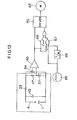
- FIG. 13 schematically illustrates a motor control circuit in which a stepping motor is used for feeding the machining electrode 4 toward the workpiece 1, and also shows an electrical discharge machining circuit.
- a portion enclosed by a dotted line is the electrical discharge machining circuit, while the remainder serves as the motor control circuit corresponding to the servo control circuit 48 shown in FIG. 2.
- Denoted at 4 is the machining electrode, I the workpiece, 45 the capacitor, 23 the resistor, and 37 the power supply.
- the motor control circuit includes a reference voltage detecting resistor 64, a comparator 65 for comparing voltages generated by the resistors 47, 64, an AND gate 66 for rotating the motor 43 at a low speed, an AND gate 67 for reversing the motor at a high speed on short-circuiting, an oscillator 68 for generating a reference rotation signal, a 1/N counter 69, and a driver amplifier 70 for driving the motor 43.
- the reference rotation signal is frequency-divided by the 1/N counter 69.
- a signal from the 1/N counter 69 is applied through the AND gate 66 to the driver amplifier 70 for rotating the motor 43 at a contant low speed.
- the signal from the oscillator 68 goes through the AND gate 67 to the driver amplifier 70 which rotates the motor 43 at a high speed in the opposite direction.
- FIGS. 14 and 15 are illustrative of a machining electrode according to another embodiment of the present invention.
- the mandrel 53 and the guide sleeve 54 in the embodiment of FIGS. 3 and 4 are integrally formed of the same material.
- a thin electrode core wire 51 is guided by a wire guide or support tube 52 of ceramics which is disposed in and attached to a mandrel or rotatable support body 53 made of metal such as quenched steel.
- the wire guide 52 is fitted in the mandrel 53, as shown in FIG. 15, with a clearance as prescribed by JIS h6 - P6.
- the wire guide 52 is composed of a cermics pipe for use as an optical fiber connector, with the error of concentricity bewteen the outer peripheral surface and the bore being 1 micrometer or less.
- the mandrel 53 is machined to render its outer peripheral surface and bore concentric with each other, with a concentricity error being 1 micrometer or smaller.
- the wire guide 52 is fitted in the mandrel 53 in a manner to reduce any possible diplacement of the electrode core wire 51 to a minimum.
- the distance that the wire guide 52 is inserted longitudianlly in the mandrel 53 is sufficiently larger as compared with the diameter of the wire guide 52, so that the wire guide 52 will not be tilted appreciably with respect to the longitudinal axis thereof.
- the electrode core wire 51 is subjected to only a greatly reduced displacement.
- the mandrel 53 may be bored in an ordinary manner, such for example as by being drilled and then finished with a reamer. Since the tool used is of a sufficient rigidity, the bore formed in the mandrel and the outer peripheral surface thereof can be concentric with each other with a concentricity error of a few micrometers.
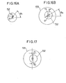
- FIG. 16A illustrates the positional relationship between the bore and outer peripheral surface of the wire guide 52
- FIG. 16B shows the positional relationship between the bore and outer peripheral surface of the mandrel 53.
- the center O' of the bore in the wire guide 52 is radially displaced r 1 from the center O of the circular outer peripheral surface of the wire guide 52 at an angular position ⁇ 1 .
- the center O"' of the bore in the mandrel 53 is radially displaced r 2 from the center O" of the circular outer peripheral surface of the mandrel 53 at an angular position ⁇ 2 .
- the mandrel 53 When combining the wire guide 52 and the mandrel 53 together in fitting engagement with each other, the mandrel 53 is angularly moved clockwise about its own axis through an angle of 6 2 in FIG. 16B, and the wire guide 52 is angularly moved counterclockwise about its own axis through an angle of 180 - 6 1 .
- the resulting relative angular positional relationship between the wire guide 52 and the mandrel 53 is illustrated in FIG. 17. More specifically, the error of concentricity R between the bore in the wire guide 52 and the outer peripheral surface of the mandrel 53 can be expressed by the following equation:
- the concentricity of the bore in the wire guide 52 fitted in the mandrel 53 with respect to the outer peripheral surface of the mandrel 53 is better than the concentricity of the bore in the wire guide 52 with respect to the outer peripheral surface thereof.
- the machining electrode with no substantial core wire displacement can therefore be achieved by combining the wire guide 52 and the mandrel 53 which have bore concentricity errors of a few micrometers.
- a tool microscope having a magnification of 800x is used to determine concentricity errors of the bores in the wire guide 52 and the mandrel 53, and the angular positions ⁇ 1 , e 2 to determine a relative angular position in which to assemble the wire guide 52 and the mandrel 53, followed by forcing the wire guide 52 into the mandrel 53 in the determined relative angular position.
- the bore in the wire guide 52 and the guide sleeve 54 or the mandrel 53 have a concentricy error of 2 microns or less, which substantially prevents the electrode core wire 51 from being displaced during electrical discharge machining so that a minute hole can be formed which has quite small out-of-roundness and reduced surface roughness.
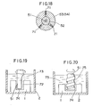
- the position of the wire guide 52 with respect to the guide sleeve 54 or the mandrel 53 may be adjusted in the radial direction as shown in FIG. 18. More specifically, the guide sleeve 54 or the mandrel 53 surrounding the wire guide 52 has three radial adjustment screws 71 threadedly disposed therein at about 120°-spaced intervals and having tip ends positionable in contact with the outer peripheral surface of the wire guide 52. By adjusting the adjustment screws 71 while observing the position of the wire guide 52 as with a microscope, the wire guide 52 can be positioned into highly concentric relation to the guide sleeve 54 or the mandrel 53.
- FIGS. 19 and 20 illustrate machining electrodes having chip discharge passages according to further embodiments of the present invention.
- an electrode core wire 51 has a recess 72 extending upwardly from a tip thereof.
- the workpiece 1 is immersed in an insulative oil 73 such as illuminating kerosene in the machining bath 2.
- chips 74 produced from the machined workpiece 1 can easily find their way into the oil 73.
- chips 74 are discharged through the recess 72 serving as a chip discharge passage into the oil 73.
- a machining electrode core wire 51 has a chip discharge passage in the form of a helical groove 75 for allowing chips 74 from the workpiece 1 to be discharged along the helical groove 75 into the oil 73.
- FIGS. 21A, 21B, and 21C show a support or bearing 77 according to a still further embodiment of the invention for supporting the machining electrode 4 through a pivot bearing construction.
- the bearing 77 has upper and lower V-grooved or notched members 77a each accommodating two protruding members 76 having semispherical distal ends projecting on surfaces defining the V-shaped groove.
- the machining electrode 4 is therefore supported by the four protruding members 76.
- Each V-shaped groove should preferably have an opening angle a in the range of from 30° to 150°.
- the protruding member 76 has a semispherical member 78 and a cover body 79 in which the semispherical member 78 is partly embedded.
- the cover body 79 is threaded or fitted in a hole defined in the V-grooved member 77a.
- the semispherical member 78 is made of ruby in the illustrated embodiment, but may also be made of a highly wear-resistant material.
- the member 78 may be flat at the distal end.
- a mode of operation of the electrical discharge machining apparatus in which a number of holes are formed in a workpiece will be described with reference to FISS. 22A, 22B, 23A, and 23B.
- FIG. 22A illustrates a workpiece I with a number of holes formed therein along a straight line.
- a reference surface A and a line B connecting the centers of the holes K it should generally be questioned how parallel are a reference surface A and a line B connecting the centers of the holes K. Stated otherwise, the angle e (FIG. 22B) formed between the reference surface A and the line B should be as small as possible.
- Such desired parallelism between the surface A and the line B can be achieved in the following manner:
- the machining electrode position H and the microscope position I (FIG. 1) are first brought into conjugate relationship, and then the center of a desired position Bl on the workpiece which is to be perforated is aligned with the crossing point of cross hairs 81 in a field of view 80 of the microscope, as shown in FIG. 23A.
- the slide 17 (FIG. 1) is moved in the Y direction by means of the feed screw 18 to observe desired positions B2 through BN succssively with the microscope 12.
- the rotatable slide 26 (FIG. 11) is angularly moved through 8 by means of the adjustment screw 27 until the straight line on the workpiece 1 coincides with the Y direction so that the desired machining positions B2 through BN will not be progressively deviated from the crossing point of the cross hairs 81 when the positions B2 through BN are successively observed with the microscope 12.
- the slide table 14 is moved toward the machining electrode 4, and the slide 17 is moved progressively in increments in the Y direction by means of the feed screw 18 while holes are formed in the workpiece 1 successively at the desired positions Bl through BN.
- the formed holes are accurately aligned along a straight line without suffering from any unwanted angular error with respect to the Y direction or the reference surface.
- the positioning mechanism in the EDM apparatus according to the present invention can be incorporated not only in electrical discharge machining for forming minute holes, but also in microdrilling, laser machining, and other types of machining employing the machining head for forming small holes in workpieces.
- minute holes can be formed at a high speed in a workpiece at positions accurately determined in a non-contact fashion without any parallax.
- the electrode core wire therein is subjected to no appreciable displacement relative to the mandrel or rotatable support body, whereby minute holes of small out-of-roundness, high shape accuracy, and surface roughness of 1 micron or smaller can be formed in the workpiece.
- the electrode core wire is consumed, it can be fed out from within the rotatable support body. Since a commercially available thin core wire can be used as the electrode core wire, a machining electrode of a long service life can easily be manufactured.
Landscapes
- Engineering & Computer Science (AREA)
- Mechanical Engineering (AREA)
- Physics & Mathematics (AREA)
- Thermal Sciences (AREA)
- Chemical & Material Sciences (AREA)
- Chemical Kinetics & Catalysis (AREA)
- Electrochemistry (AREA)
- Optics & Photonics (AREA)
- Electrical Discharge Machining, Electrochemical Machining, And Combined Machining (AREA)
Applications Claiming Priority (6)
| Application Number | Priority Date | Filing Date | Title |
|---|---|---|---|
| JP58088529A JPS59214544A (ja) | 1983-05-19 | 1983-05-19 | 微小穴加工装置 |
| JP88530/83 | 1983-05-19 | ||
| JP88512/83 | 1983-05-19 | ||
| JP58088530A JPS59214519A (ja) | 1983-05-19 | 1983-05-19 | 放電加工装置 |
| JP88529/83 | 1983-05-19 | ||
| JP58088512A JPS59214518A (ja) | 1983-05-19 | 1983-05-19 | 微小穴放電加工用電極構体 |
Publications (2)
| Publication Number | Publication Date |
|---|---|
| EP0129340A1 true EP0129340A1 (de) | 1984-12-27 |
| EP0129340B1 EP0129340B1 (de) | 1988-11-17 |
Family
ID=27305834
Family Applications (1)
| Application Number | Title | Priority Date | Filing Date |
|---|---|---|---|
| EP84303406A Expired EP0129340B1 (de) | 1983-05-19 | 1984-05-18 | Elektrische Funkenerosionsvorrichtung zur Herstellung von Feinbohrungen |
Country Status (2)
| Country | Link |
|---|---|
| EP (1) | EP0129340B1 (de) |
| DE (1) | DE3475172D1 (de) |
Cited By (9)
| Publication number | Priority date | Publication date | Assignee | Title |
|---|---|---|---|---|
| US4888462A (en) * | 1987-02-03 | 1989-12-19 | Charmilles Technologies S.A. | Device and process for machining by electroerosion |
| ES2038907A2 (es) * | 1991-09-20 | 1993-08-01 | Ona Electro Erosion | Dispositivo de control de posicion de un elemento movil en una maquina de electroerosion. |
| EP0826455A1 (de) * | 1996-09-03 | 1998-03-04 | Sarix S.A. | Automatische Greifvorrichtung für Funkenerosionselektroden |
| CN102275021A (zh) * | 2011-07-21 | 2011-12-14 | 北京迪蒙吉意超硬材料技术有限公司 | 一种工件旋转的高压电火花束流加工装置及加工方法 |
| CN107297643A (zh) * | 2017-06-23 | 2017-10-27 | 芜湖仅机械有限公司 | 一种通讯基站内部支架的全自动钻孔生产线的下料机构 |
| CN107470948A (zh) * | 2017-06-23 | 2017-12-15 | 芜湖仅机械有限公司 | 一种通讯基站内部支架的全自动钻孔生产线的定位机构 |
| CN113399884A (zh) * | 2021-07-09 | 2021-09-17 | 昆山德盛精密模具有限公司 | 模具内连续焊接结构 |
| CN114433967A (zh) * | 2022-03-28 | 2022-05-06 | 浙江亚微精密机床有限公司 | 电火花/电解机床的电极棒可转位支撑结构 |
| CN115780932A (zh) * | 2022-12-27 | 2023-03-14 | 扬州大学 | 一种电解-磨削精密扩孔加工装置 |
Families Citing this family (1)
| Publication number | Priority date | Publication date | Assignee | Title |
|---|---|---|---|---|
| US12569923B1 (en) | 2024-11-18 | 2026-03-10 | King Saud University | Micro-electric discharge milling machine with spark control |
Citations (8)
| Publication number | Priority date | Publication date | Assignee | Title |
|---|---|---|---|---|
| CH366439A (de) * | 1958-06-14 | 1962-12-31 | Hans Dr Ing Deckel | Werkzeugmaschine zur Herstellung von Formen, Gesenken usw. |
| US3806691A (en) * | 1972-11-20 | 1974-04-23 | Cammann Mfg Co | Tool positioner |
| DE1565554B2 (de) * | 1965-07-26 | 1975-06-05 | Gen Electric | Verfahren und Vorrichtung zur elektrolytischen Herstellung von Löchern oder Hohlräumen in einem elektrisch leitenden Werkstück |
| US4123645A (en) * | 1976-02-25 | 1978-10-31 | Fujitsu Fanuc Limited | Numerically controlled wire-cutting electric discharge machine |
| DE2721576A1 (de) * | 1977-05-13 | 1978-11-16 | Aeg Elotherm Gmbh | Einrichtung zur elektroerosiven bearbeitung metallener werkstuecke |
| DE3032604A1 (de) * | 1979-08-30 | 1981-03-19 | Inoue-Japax Research Inc., Yokohama, Kanagawa | Verfahren und vorrichtung zum elektroerosiven bearbeiten |
| GB2069396A (en) * | 1980-02-18 | 1981-08-26 | Inoue Japax Res | Wire-cutting electroerosion machining method and apparatus |
| DE3203605A1 (de) * | 1981-02-03 | 1982-09-09 | Inoue-Japax Research Inc., Yokohama, Kanagawa | Verfahren und vorrichtung zum elektroerosiven bearbeiten eines profils in einem werkstueck |
-
1984
- 1984-05-18 EP EP84303406A patent/EP0129340B1/de not_active Expired
- 1984-05-18 DE DE8484303406T patent/DE3475172D1/de not_active Expired
Patent Citations (8)
| Publication number | Priority date | Publication date | Assignee | Title |
|---|---|---|---|---|
| CH366439A (de) * | 1958-06-14 | 1962-12-31 | Hans Dr Ing Deckel | Werkzeugmaschine zur Herstellung von Formen, Gesenken usw. |
| DE1565554B2 (de) * | 1965-07-26 | 1975-06-05 | Gen Electric | Verfahren und Vorrichtung zur elektrolytischen Herstellung von Löchern oder Hohlräumen in einem elektrisch leitenden Werkstück |
| US3806691A (en) * | 1972-11-20 | 1974-04-23 | Cammann Mfg Co | Tool positioner |
| US4123645A (en) * | 1976-02-25 | 1978-10-31 | Fujitsu Fanuc Limited | Numerically controlled wire-cutting electric discharge machine |
| DE2721576A1 (de) * | 1977-05-13 | 1978-11-16 | Aeg Elotherm Gmbh | Einrichtung zur elektroerosiven bearbeitung metallener werkstuecke |
| DE3032604A1 (de) * | 1979-08-30 | 1981-03-19 | Inoue-Japax Research Inc., Yokohama, Kanagawa | Verfahren und vorrichtung zum elektroerosiven bearbeiten |
| GB2069396A (en) * | 1980-02-18 | 1981-08-26 | Inoue Japax Res | Wire-cutting electroerosion machining method and apparatus |
| DE3203605A1 (de) * | 1981-02-03 | 1982-09-09 | Inoue-Japax Research Inc., Yokohama, Kanagawa | Verfahren und vorrichtung zum elektroerosiven bearbeiten eines profils in einem werkstueck |
Cited By (10)
| Publication number | Priority date | Publication date | Assignee | Title |
|---|---|---|---|---|
| US4888462A (en) * | 1987-02-03 | 1989-12-19 | Charmilles Technologies S.A. | Device and process for machining by electroerosion |
| ES2038907A2 (es) * | 1991-09-20 | 1993-08-01 | Ona Electro Erosion | Dispositivo de control de posicion de un elemento movil en una maquina de electroerosion. |
| EP0826455A1 (de) * | 1996-09-03 | 1998-03-04 | Sarix S.A. | Automatische Greifvorrichtung für Funkenerosionselektroden |
| CN102275021A (zh) * | 2011-07-21 | 2011-12-14 | 北京迪蒙吉意超硬材料技术有限公司 | 一种工件旋转的高压电火花束流加工装置及加工方法 |
| CN107297643A (zh) * | 2017-06-23 | 2017-10-27 | 芜湖仅机械有限公司 | 一种通讯基站内部支架的全自动钻孔生产线的下料机构 |
| CN107470948A (zh) * | 2017-06-23 | 2017-12-15 | 芜湖仅机械有限公司 | 一种通讯基站内部支架的全自动钻孔生产线的定位机构 |
| CN113399884A (zh) * | 2021-07-09 | 2021-09-17 | 昆山德盛精密模具有限公司 | 模具内连续焊接结构 |
| CN114433967A (zh) * | 2022-03-28 | 2022-05-06 | 浙江亚微精密机床有限公司 | 电火花/电解机床的电极棒可转位支撑结构 |
| CN114433967B (zh) * | 2022-03-28 | 2025-04-22 | 浙江亚微精密机床有限公司 | 电火花/电解机床的电极棒可转位支撑结构 |
| CN115780932A (zh) * | 2022-12-27 | 2023-03-14 | 扬州大学 | 一种电解-磨削精密扩孔加工装置 |
Also Published As
| Publication number | Publication date |
|---|---|
| DE3475172D1 (en) | 1988-12-22 |
| EP0129340B1 (de) | 1988-11-17 |
Similar Documents
| Publication | Publication Date | Title |
|---|---|---|
| US4510693A (en) | Probe with stylus adjustment | |
| EP0129340B1 (de) | Elektrische Funkenerosionsvorrichtung zur Herstellung von Feinbohrungen | |
| US4999495A (en) | Scanning tunneling microscope | |
| US4771157A (en) | Electrical discharge machining apparatus for forming minute holes in a workpiece | |
| US5046262A (en) | Spherical edge locator for machining | |
| US4654498A (en) | Electrical discharge machining electrode for forming minute holes in a workpiece and electrical discharge machining apparatus employing such an electrode | |
| CN100415429C (zh) | 电火花腐蚀加工机床的电极引导装置及工件的电火花腐蚀加工法 | |
| KR100383470B1 (ko) | 금속제거공구에의한동적인홈베어링제조방법과,동적인홈베어링을구비한데이터저장유닛 | |
| US20030024122A1 (en) | Method and apparatus for producing hydrodynamic bearing parts by electrochemical machining | |
| EP0286779B1 (de) | Drahtführung für Funkenerosionsmaschine | |
| KR20070091377A (ko) | 방전 가공 장치 | |
| JP4140877B2 (ja) | 細穴放電加工装置 | |
| JP3941647B2 (ja) | 微細工具創製装置および微細加工装置 | |
| CN116352475A (zh) | 一种斜齿轮内孔键槽加工装置 | |
| JP2966655B2 (ja) | 穴位置測定装置 | |
| US1290789A (en) | Positioning device. | |
| JPS6154531B2 (de) | ||
| US2860532A (en) | Precision drill and alignment fixture | |
| JP2023012178A (ja) | 加工位置決め方法及び位置決め用器具 | |
| US3924936A (en) | Method of and apparatus for aligning optical lenses | |
| US4791264A (en) | Low force wire guide for EDM machine | |
| US4543859A (en) | Probe adjustment tool and method of using same | |
| CN220050063U (zh) | 一种车床用偏心夹具 | |
| JPS63216651A (ja) | 機械加工方法 | |
| JPH0696239B2 (ja) | 微細穴プレス加工用ダイセット |
Legal Events
| Date | Code | Title | Description |
|---|---|---|---|
| PUAI | Public reference made under article 153(3) epc to a published international application that has entered the european phase |
Free format text: ORIGINAL CODE: 0009012 |
|
| AK | Designated contracting states |
Designated state(s): DE FR GB |
|
| 17P | Request for examination filed |
Effective date: 19850502 |
|
| 17Q | First examination report despatched |
Effective date: 19860401 |
|
| D17Q | First examination report despatched (deleted) | ||
| GRAA | (expected) grant |
Free format text: ORIGINAL CODE: 0009210 |
|
| AK | Designated contracting states |
Kind code of ref document: B1 Designated state(s): DE FR GB |
|
| REF | Corresponds to: |
Ref document number: 3475172 Country of ref document: DE Date of ref document: 19881222 |
|
| ET | Fr: translation filed | ||
| PLBE | No opposition filed within time limit |
Free format text: ORIGINAL CODE: 0009261 |
|
| STAA | Information on the status of an ep patent application or granted ep patent |
Free format text: STATUS: NO OPPOSITION FILED WITHIN TIME LIMIT |
|
| 26N | No opposition filed | ||
| REG | Reference to a national code |
Ref country code: GB Ref legal event code: 746 Effective date: 19951123 |
|
| REG | Reference to a national code |
Ref country code: FR Ref legal event code: D6 |
|
| REG | Reference to a national code |
Ref country code: GB Ref legal event code: IF02 |
|
| PGFP | Annual fee paid to national office [announced via postgrant information from national office to epo] |
Ref country code: FR Payment date: 20020508 Year of fee payment: 19 |
|
| PGFP | Annual fee paid to national office [announced via postgrant information from national office to epo] |
Ref country code: GB Payment date: 20020515 Year of fee payment: 19 |
|
| PGFP | Annual fee paid to national office [announced via postgrant information from national office to epo] |
Ref country code: DE Payment date: 20020522 Year of fee payment: 19 |
|
| PG25 | Lapsed in a contracting state [announced via postgrant information from national office to epo] |
Ref country code: GB Free format text: LAPSE BECAUSE OF NON-PAYMENT OF DUE FEES Effective date: 20030518 |
|
| PG25 | Lapsed in a contracting state [announced via postgrant information from national office to epo] |
Ref country code: DE Free format text: LAPSE BECAUSE OF NON-PAYMENT OF DUE FEES Effective date: 20031202 |
|
| GBPC | Gb: european patent ceased through non-payment of renewal fee |
Effective date: 20030518 |
|
| PG25 | Lapsed in a contracting state [announced via postgrant information from national office to epo] |
Ref country code: FR Free format text: LAPSE BECAUSE OF NON-PAYMENT OF DUE FEES Effective date: 20040130 |
|
| REG | Reference to a national code |
Ref country code: FR Ref legal event code: ST |