EP0129355B1 - Entwicklungssystem mit magnetischen, isolierenden Tonerteilchen - Google Patents
Entwicklungssystem mit magnetischen, isolierenden Tonerteilchen Download PDFInfo
- Publication number
- EP0129355B1 EP0129355B1 EP19840303672 EP84303672A EP0129355B1 EP 0129355 B1 EP0129355 B1 EP 0129355B1 EP 19840303672 EP19840303672 EP 19840303672 EP 84303672 A EP84303672 A EP 84303672A EP 0129355 B1 EP0129355 B1 EP 0129355B1
- Authority
- EP
- European Patent Office
- Prior art keywords
- development
- magnetic
- developer
- developer material
- belt
- Prior art date
- Legal status (The legal status is an assumption and is not a legal conclusion. Google has not performed a legal analysis and makes no representation as to the accuracy of the status listed.)
- Expired
Links
- 238000011161 development Methods 0.000 title claims description 59
- 230000005291 magnetic effect Effects 0.000 title claims description 39
- 239000002245 particle Substances 0.000 title claims description 27
- 239000000463 material Substances 0.000 claims description 51
- 239000000843 powder Substances 0.000 claims description 15
- 239000008187 granular material Substances 0.000 claims description 14
- 239000000696 magnetic material Substances 0.000 claims description 2
- 239000006249 magnetic particle Substances 0.000 claims description 2
- 239000007787 solid Substances 0.000 description 7
- 238000012546 transfer Methods 0.000 description 6
- 238000004140 cleaning Methods 0.000 description 5
- 239000011347 resin Substances 0.000 description 4
- 229920005989 resin Polymers 0.000 description 4
- 150000001412 amines Chemical class 0.000 description 3
- 239000000203 mixture Substances 0.000 description 3
- 229920006122 polyamide resin Polymers 0.000 description 3
- 238000012545 processing Methods 0.000 description 3
- QGZKDVFQNNGYKY-UHFFFAOYSA-N Ammonia Chemical compound N QGZKDVFQNNGYKY-UHFFFAOYSA-N 0.000 description 2
- XEEYBQQBJWHFJM-UHFFFAOYSA-N Iron Chemical compound [Fe] XEEYBQQBJWHFJM-UHFFFAOYSA-N 0.000 description 2
- UQSXHKLRYXJYBZ-UHFFFAOYSA-N Iron oxide Chemical compound [Fe]=O UQSXHKLRYXJYBZ-UHFFFAOYSA-N 0.000 description 2
- 239000004952 Polyamide Substances 0.000 description 2
- 229910052782 aluminium Inorganic materials 0.000 description 2
- XAGFODPZIPBFFR-UHFFFAOYSA-N aluminium Chemical compound [Al] XAGFODPZIPBFFR-UHFFFAOYSA-N 0.000 description 2
- 235000014113 dietary fatty acids Nutrition 0.000 description 2
- 229930195729 fatty acid Natural products 0.000 description 2
- 239000000194 fatty acid Substances 0.000 description 2
- 150000004665 fatty acids Chemical class 0.000 description 2
- 230000005294 ferromagnetic effect Effects 0.000 description 2
- 229910052751 metal Inorganic materials 0.000 description 2
- 239000002184 metal Substances 0.000 description 2
- 229920002647 polyamide Polymers 0.000 description 2
- 239000000758 substrate Substances 0.000 description 2
- 229910000531 Co alloy Inorganic materials 0.000 description 1
- VGGSQFUCUMXWEO-UHFFFAOYSA-N Ethene Chemical compound C=C VGGSQFUCUMXWEO-UHFFFAOYSA-N 0.000 description 1
- 239000005977 Ethylene Substances 0.000 description 1
- 238000006424 Flood reaction Methods 0.000 description 1
- 229910000990 Ni alloy Inorganic materials 0.000 description 1
- 239000004793 Polystyrene Substances 0.000 description 1
- 229910001370 Se alloy Inorganic materials 0.000 description 1
- BUGBHKTXTAQXES-UHFFFAOYSA-N Selenium Chemical class [Se] BUGBHKTXTAQXES-UHFFFAOYSA-N 0.000 description 1
- 230000009471 action Effects 0.000 description 1
- 238000013019 agitation Methods 0.000 description 1
- 229910021529 ammonia Inorganic materials 0.000 description 1
- 238000013459 approach Methods 0.000 description 1
- 229940090961 chromium dioxide Drugs 0.000 description 1
- IAQWMWUKBQPOIY-UHFFFAOYSA-N chromium(4+);oxygen(2-) Chemical compound [O-2].[O-2].[Cr+4] IAQWMWUKBQPOIY-UHFFFAOYSA-N 0.000 description 1
- AYTAKQFHWFYBMA-UHFFFAOYSA-N chromium(IV) oxide Inorganic materials O=[Cr]=O AYTAKQFHWFYBMA-UHFFFAOYSA-N 0.000 description 1
- 229910017052 cobalt Inorganic materials 0.000 description 1
- 239000010941 cobalt Substances 0.000 description 1
- GUTLYIVDDKVIGB-UHFFFAOYSA-N cobalt atom Chemical compound [Co] GUTLYIVDDKVIGB-UHFFFAOYSA-N 0.000 description 1
- 230000006835 compression Effects 0.000 description 1
- 238000007906 compression Methods 0.000 description 1
- 229920001577 copolymer Polymers 0.000 description 1
- 230000002939 deleterious effect Effects 0.000 description 1
- 238000012217 deletion Methods 0.000 description 1
- 230000037430 deletion Effects 0.000 description 1
- 150000002148 esters Chemical class 0.000 description 1
- 238000003384 imaging method Methods 0.000 description 1
- 239000011810 insulating material Substances 0.000 description 1
- 230000003993 interaction Effects 0.000 description 1
- 150000002500 ions Chemical class 0.000 description 1
- 229910052742 iron Inorganic materials 0.000 description 1
- SZVJSHCCFOBDDC-UHFFFAOYSA-N iron(II,III) oxide Inorganic materials O=[Fe]O[Fe]O[Fe]=O SZVJSHCCFOBDDC-UHFFFAOYSA-N 0.000 description 1
- 238000002844 melting Methods 0.000 description 1
- 230000008018 melting Effects 0.000 description 1
- 238000000034 method Methods 0.000 description 1
- 230000003287 optical effect Effects 0.000 description 1
- 230000002093 peripheral effect Effects 0.000 description 1
- 229920000728 polyester Polymers 0.000 description 1
- 238000006116 polymerization reaction Methods 0.000 description 1
- 229920002223 polystyrene Polymers 0.000 description 1
- 230000008569 process Effects 0.000 description 1
- 238000011160 research Methods 0.000 description 1
- 230000004044 response Effects 0.000 description 1
- 238000007790 scraping Methods 0.000 description 1
- 150000003335 secondary amines Chemical class 0.000 description 1
- 230000035945 sensitivity Effects 0.000 description 1
- 238000010008 shearing Methods 0.000 description 1
- 239000007921 spray Substances 0.000 description 1
- 239000000126 substance Substances 0.000 description 1
- 230000032258 transport Effects 0.000 description 1
- 229940117958 vinyl acetate Drugs 0.000 description 1
Images


Classifications
-
- G—PHYSICS
- G03—PHOTOGRAPHY; CINEMATOGRAPHY; ANALOGOUS TECHNIQUES USING WAVES OTHER THAN OPTICAL WAVES; ELECTROGRAPHY; HOLOGRAPHY
- G03G—ELECTROGRAPHY; ELECTROPHOTOGRAPHY; MAGNETOGRAPHY
- G03G15/00—Apparatus for electrographic processes using a charge pattern
- G03G15/75—Details relating to xerographic drum, band or plate, e.g. replacing, testing
- G03G15/754—Details relating to xerographic drum, band or plate, e.g. replacing, testing relating to band, e.g. tensioning
-
- G—PHYSICS
- G03—PHOTOGRAPHY; CINEMATOGRAPHY; ANALOGOUS TECHNIQUES USING WAVES OTHER THAN OPTICAL WAVES; ELECTROGRAPHY; HOLOGRAPHY
- G03G—ELECTROGRAPHY; ELECTROPHOTOGRAPHY; MAGNETOGRAPHY
- G03G13/00—Electrographic processes using a charge pattern
- G03G13/06—Developing
- G03G13/08—Developing using a solid developer, e.g. powder developer
- G03G13/09—Developing using a solid developer, e.g. powder developer using magnetic brush
-
- G—PHYSICS
- G03—PHOTOGRAPHY; CINEMATOGRAPHY; ANALOGOUS TECHNIQUES USING WAVES OTHER THAN OPTICAL WAVES; ELECTROGRAPHY; HOLOGRAPHY
- G03G—ELECTROGRAPHY; ELECTROPHOTOGRAPHY; MAGNETOGRAPHY
- G03G15/00—Apparatus for electrographic processes using a charge pattern
- G03G15/06—Apparatus for electrographic processes using a charge pattern for developing
- G03G15/08—Apparatus for electrographic processes using a charge pattern for developing using a solid developer, e.g. powder developer
- G03G15/09—Apparatus for electrographic processes using a charge pattern for developing using a solid developer, e.g. powder developer using magnetic brush
Definitions
- This invention relates to a development system for developing a latent image recorded on a flexible member.
- the system is of the kind comprising a developer material and a development apparatus for applying the developer material to the latent image, the developer material comprising carrier grannules and toner particles, and the apparatus including
- the developer material is made from a mixture of carrier granules and toner particles.
- the toner particles adhere triboelectrically to the carrier granules. This two-component mixture is brought into contact with the latent image. Toner particles are attracted from the carrier granules to the latent image forming a powder image thereof.
- Most electrophotographic printing machines employ a magnetic brush development system for developing the latent image.
- the magnetic brush development system may use one or more developer rollers for transporting the developer material closely adjacent to the photoconductive surface.
- Magnetic brush development systems employ either a conductive developer material or an insulating developer material.
- the conductive magnetic brush development system and the insulating magnetic brush development system suffer from limitations in their abilities to meet the full range of copy quality requirements.
- insulating magnetic brush development systems have difficulty in developing large solid areas.
- the spacing between the developer roller and photoconductive surface must be made quite small.
- the solid area development is improved in this manner, other problems arise. For example, there is an increase in the severity of the cleaning field-related edge deletions typical of insulating magnetic brush development.
- several developer rollers were required to overcome these problems. However, the utilization of additional developer rollers increases the cost of the development system.
- Conductive magnetic brush development systems inherently fail to reproduce low density lines when the electrical bias on the developer roll is increased in order to suppress the development of background areas'.
- Conductive developer materials are not sensitive to fringe fields. In order to achieve low density fine line development with conductive developer materials, the cleaning fields must be relatively low. This produces relatively high background.
- With the increased use of flexible photoconductive belts and magnetic brush developer rollers it has become more feasible to control the spacing therebetween. When the photoconductive belt is maintained at the proper tensioning, it has now become practical to permit the developer material to space the photoconductive belt from the developer roller. In this way, insulating developer materials may be used and still provide relatively satisfactory solid area development. . However, this still does not solve the other problems associated with a system of this type.
- the present invention is intended to overcome the disadvantages of the prior art, and provides a development system of the kind specified which is characterised in that said magnetic means has a magnetic pole located in the development zone and that the toner particles are insulating, magnetic particles.
- an electrophotographic printing machine of the type having an electrostatic latent image recorded on a flexible photoconductive member and including the above defined development system.
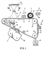
- FIG. 1 schematically depicts the various components of an electrophotographic printing machine employing the development system of the present invention therein.
- this development system is particularly well adapted for use in the illustrative electrophotographic printing machine, it will become evident from the following discussion that it is equally well suited for use in a wide variety of electrostatographic printing machines and is not necessarily limited in its application to the particular embodiment shown herein.
- the electrophotographic printing machine employs a belt 10 having a photoconductive surface deposited on a conductive substrate.
- the photoconductive surface is made from a selenium alloy.
- the conductive substrate is made preferably from aluminum which is electrically grounded.
- Belt 10 removes in the direction of arrow 12 to advance successive portions of the photoconductive surface sequentially through the various processing stations disposed about the path of movement thereof.
- the path of movement of belt 10 is defined by stripping roller 14, tensioning system 16, and drive roller 18.
- tensioning system 16 includes a roller 20 over which belt 10 moves.
- Roller 20 is mounted rotatably in yoke 22.
- drive roller 18 is mounted rotatably and in engagement with belt 10.
- Motor 26 rotates roller 18 to advance belt 10 in the direction of arrow 12.
- Roller 18 is coupled to motor 26 by suitable means such as a belt drive.
- Stripping roller 14 is freely rotatable so as to permit belt 10 to move in the direction of arrow 12 with a minimum of friction.
- a corona generating device indicated generally by the reference numeral 28, charges the photoconductive surface of belt 10 to a relatively high, substantiaily uniform potential.
- the charged portion of the photoconductive surface is advanced through exposure station B.
- an original document 30 is positioned facedown upon transparent platen 32.
- Lamps 34 flash light rays onto original document 30.
- the light rays reflected from original document 30 are transmitted through lens 36 forming a light image thereof.
- Lens 36 focuses the light image onto the charged portion of the photoconductive surface to selectively dissipate the charge thereon. This records an electrostatic latent image on the photoconductive surface which corresponds to the informational areas contained within original document 30.
- a laser beam may be employed to irradiate the charged portion of the photoconductive surface to form an electrostatic latent image thereon. Modulation of the laser beam is achieved by processing signals corresponding to information desired to be reproduced and, in turn, controlling the laser beam modulation in accordance therewith.
- magnetic brush development system 38 advances an insulating developer material into contact with the electrostatic latent image.
- magnetic brush development system 38 includes a developer roller 40.
- Developer rolier 40 transports a brush of developer material comprising magnetic carrier granules and insulating, magnetic toner particles into contact with belt 10.
- developer roller 40 is positioned such that the brush of developer material deflects belt 10 between idler rollers 42 in an arc with belt 10 conforming, at least partially, to the configuration of the developer material and wrapping around developer roller 40 to form an extended development zone.
- the electrostatic latent image attracts the insulating, magnetic toner particles from the carrier granules forming a toner powder image on the photoconductive surface of belt 10.
- belt 10 advances the toner powder image to transfer station D.
- a sheet of support material 44 is moved into contact with the toner powder image.
- Sheet of support material 44 is advanced to transfer station D by a sheet feeding apparatus (not shown).
- the sheet feeding apparatus may include a feed roll contacting the uppermost sheet of a stack of sheets. The feed roll rotates so as to advance the uppermost sheet from the stack into a chute. The chute directs the advancing sheet of support material into contact with the photoconductive surface of belt 10 in a timed sequence so that the toner powder image developed thereon contacts the advancing sheet of support material at transfer station D.
- Transfer station D includes a corona generating device 46 which sprays ions onto the back side of sheet 44. This attracts the toner powder image from the photoconductive surface to sheet 44. After transfer, sheet 44 moves in the direction of arrow 48 onto a conveyor (not shown) which advances sheet 44 to fusing station E.
- Fusing station E includes a fuser assembly, indicated generaily by the reference numeral 50, which permanently affixes the toner powder image to sheet 44.
- fuser assembly 50 includes a heated fuser roller 52 and a back-up roller 54.
- Sheet 44 passes between fuser roller 52 and back-up roller 54 with the toner powder image contacting fuser rolier 52. In this manner, the toner powder image is permanently affixed to sheet 44.
- a chute guides the advancing sheet 44 to a catch tray for subsequent removal from the printing machine by the operator.
- Cleaning station F includes a rotatably mounted fibrous brush 56 in contact with the photoconductive surface. The particles are cleaned from the photoconductive surface by the rotation of brush 56. Subsequent to cleaning, a discharge lamp (not shown) floods the photoconductive surface with light to dissipate any residual electrostatic charge remaining thereon prior to the charging thereof for the next successive imaging cycle.
- tensioning system 16 includes roller 20 having belt 10 passing there over.
- Roller 20 is mounted in suitable bearings in a yoke, indicated generally by the reference numeral 22.
- yoke 22 includes a U-shaped member 58 supporting roller 20 and a rod 60 secured to the mid-point of cross member 62 of U-shaped member 58.
- Coil spring 24 is wrapped around rod 60.
- Rod 60 is mounted slidably in the printing machine frame 66.
- Spring 24 is compressed between cross member 62 and frame 66. Compressed spring 24 resiliently urges yoke 22 and, in turn, roller 20 against belt 10.
- Spring 24 is designed to have the appropriate spring constant such that when placed under the desired compression, belt 10 is tensioned from about 0.1 to about 0.15 kilograms per linear centimeter. Belt 10 is maintained under a sufficiently low tension to enable the developer material on developer roll 40 to deflect belt 10 through an extended development zone corresponding to an arc ranging from about 10° to about 40°.
- Development system 38 includes a housing 68 defining a chamber for storing a supply of insulating developer material therein.
- the insulating developer material includes carrier granules and insulating, magnetic toner particies.
- the carrier granules have the magnetic toner particles adhering thereto triboelectrically. In this way, during the developing process, the insulating, magnetic toner particles are attracted from the carrier granules to the latent image forming a toner powder image thereon.
- a pair of augers 70 mix the developer material in the chamber of housing 68 and advance the developer material to developer roller 40.
- Developer roller 40 advances the insulating developer material into contact with the electrostatic latent image recorded on the photoconductive surface of belt 10.
- a trim bar 72 regulates the thickness of the developer pile height on developer roller 40.
- the tangential velocity of deveioper roller 40 is in the same direction and at about two to three times the magnitude of the velocity of belt 10.
- the compressed pile height of the developer material ranges from about 0.05 centimeters to about 0.10 centimeters.
- Trim bar 72 extends in a longitudinal direction substantially across the width of developer roller 40 so as to provide a uniform gap controlling the quantity of insulating developer material being moved into development zone 74.
- Developer roller 40 includes a non-magnetictubu- lar member 76 preferably made from aluminum having the exterior circumferential surface thereof roughened.
- Elongated magnet 78 is positioned concentrically within tubular member 76 and mounted on shaft 80. Magnet 78 has magnetic poles impressed about the circumferential surface thereof. Developer material being transported into development zone 74 becomes highly agitated due to the shearing action between the brush of developer material and the photoconductive surface facilitating development of the latent image. Blade 82 assists in scraping the used developer material from tubular member 76.
- tubular member 76 is electrically biased by a voltage source (not shown) to a suitable polarity and magnitude.
- the voltage level is intermediate that of the background voltage and the image voltage level recorded on the photoconductive surface of belt 10.
- the voltage source electrically biases tubular member 76 to a voltage ranging from about 0 volts to about 100 volts relative to the background voltage on the photoconductive surface.
- a brush of developer material is formed on the peripheral surface thereof.
- the brush of developer material advances into contact with belt 10 in development zone 74.
- the brush of developer material in development zone 74 deflects belt 10 to wrap about developer roller 40 to form an extended development zone.
- Magnetic member 78 is mounted stationary to attract the insulating developer material to tubular member 76 due to the magnetic properties of both the carrier granules and the toner particles adhering triboelectrically thereto.
- development zone 74 the magnetic, insulating toner particles are attracted from the carrier granules to the latent image to form a toner powder image on the photoconductive surface of belt 10.
- the insulating developer material has a resistivity ranging from about 1012 to about 1017 ohm-cm.
- the developer material comprises carrier granules having insulating, magnetic toner particles adhering triboelectrically thereto.
- the toner particles may be made from a magnetic material such as a ferromagnetic metal embedded in an insulating material such as a polyamide resin.
- polyamide resin refers to the polymerization product resulting from, the interaction of a poly fatty acid or the ester of a poly fatty acid with ammonia and an amine selected from the group consisting primarily of amines, secondary amines and alkylated amines.
- any polyamide resin may be employed providing the melting point of the resin is within the range of about 70°C to about 165°C. Below 70°C, there is a danger of the resin being melted at the normal operating temperature of the printing machine, while temperatures above 165°C cause charring of the copy sheet and may have deleterious effects on the printing machine.
- suitable polyamides are the Versamid 930, 940 and 950 resins of General Mills, Inc., and the polyamide 1155, 1144 and 1074 resins of Lawter Chemical Company. Other materials such as polystyrenes, polyesters or ethylene/vinylacetate copolymers may be utilized as well. Any suitable ferromagnetic metal may be employed.
- particles of iron, magnetic iron oxide, magnetite, nickel alloys, cobalt, cobalt alloys or chromium dioxide may also be used.
- the major dimensions of the toner particles may range from lpm to 300pm with the preferred range being from 5pm to 30pm.
- the use of insulating, magnetic toner particles increases the adhesion between the carrier granules and toner particles, reduces the required electrical bias on the developer roll, and permits increased spacing between the developer roll and photoconductive surface. This results in improved copy quality and less dirt in the printing machine.
- the development apparatus of the present invention includes a developer roller transporting a developer material comprising carrier granules and insulating, magnetic toner particles into contact with the electrostatic latent image recorded on the photoconductive surface.
- the belt is maintained at a preselected tension of sufficient magnitude to enable the insulating developer material to deflect the belt in the development zone. In this way, an extended development zone is formed having high agitation therein and the improved development of solid areas by the insulating magnetic toner particles.
Landscapes
- Physics & Mathematics (AREA)
- General Physics & Mathematics (AREA)
- Dry Development In Electrophotography (AREA)
Claims (5)
Applications Claiming Priority (2)
| Application Number | Priority Date | Filing Date | Title |
|---|---|---|---|
| US50392583A | 1983-06-13 | 1983-06-13 | |
| US503925 | 1983-06-13 |
Publications (3)
| Publication Number | Publication Date |
|---|---|
| EP0129355A2 EP0129355A2 (de) | 1984-12-27 |
| EP0129355A3 EP0129355A3 (en) | 1985-05-29 |
| EP0129355B1 true EP0129355B1 (de) | 1989-09-06 |
Family
ID=24004102
Family Applications (1)
| Application Number | Title | Priority Date | Filing Date |
|---|---|---|---|
| EP19840303672 Expired EP0129355B1 (de) | 1983-06-13 | 1984-05-31 | Entwicklungssystem mit magnetischen, isolierenden Tonerteilchen |
Country Status (3)
| Country | Link |
|---|---|
| EP (1) | EP0129355B1 (de) |
| JP (1) | JPS604965A (de) |
| DE (1) | DE3479687D1 (de) |
Families Citing this family (2)
| Publication number | Priority date | Publication date | Assignee | Title |
|---|---|---|---|---|
| JPH0398459U (de) * | 1990-01-29 | 1991-10-14 | ||
| CN111665701B (zh) * | 2020-07-17 | 2025-03-07 | 珠海天威飞马打印耗材有限公司 | 碳粉盒及打印机 |
Family Cites Families (4)
| Publication number | Priority date | Publication date | Assignee | Title |
|---|---|---|---|---|
| JPS5662256A (en) * | 1979-10-24 | 1981-05-28 | Minolta Camera Co Ltd | Electrophotographic developer and developing method |
| JPS56104359A (en) * | 1980-01-11 | 1981-08-20 | Xerox Corp | Electronic photography copier developing device |
| US4368970A (en) * | 1980-06-02 | 1983-01-18 | Xerox Corporation | Development process and apparatus |
| CA1169716A (en) * | 1980-06-02 | 1984-06-26 | Xerox Corporation | Self-agitated development process |
-
1984
- 1984-05-07 JP JP59090825A patent/JPS604965A/ja active Pending
- 1984-05-31 DE DE8484303672T patent/DE3479687D1/de not_active Expired
- 1984-05-31 EP EP19840303672 patent/EP0129355B1/de not_active Expired
Also Published As
| Publication number | Publication date |
|---|---|
| EP0129355A2 (de) | 1984-12-27 |
| DE3479687D1 (en) | 1989-10-12 |
| EP0129355A3 (en) | 1985-05-29 |
| JPS604965A (ja) | 1985-01-11 |
Similar Documents
| Publication | Publication Date | Title |
|---|---|---|
| EP0058065B1 (de) | Vorrichtung zur Entwicklung eines latenten Bildes | |
| US4876575A (en) | Printing apparatus including apparatus and method for charging and metering toner particles | |
| US4397264A (en) | Electrostatic image development system having tensioned flexible recording member | |
| EP0533347B1 (de) | Entwicklungssystem | |
| US4565437A (en) | Hybrid development system | |
| EP0046684B1 (de) | Vorrichtung zum Entfernen von Teilchen von einem flexiblen Teil | |
| US4537494A (en) | Multi-roll development system | |
| US4398496A (en) | Multi-roll development system | |
| US4641946A (en) | Development system | |
| EP0130832B1 (de) | Entwicklungssystem mit mehreren Geschwindigkeiten | |
| US4723144A (en) | Developing or cleaning unit for an electrophotographic printing machine | |
| US5204719A (en) | Development system | |
| EP0132932B1 (de) | Entwicklungseinrichtung mit einer magnetischen Rührwelle | |
| EP0129355B1 (de) | Entwicklungssystem mit magnetischen, isolierenden Tonerteilchen | |
| US4105320A (en) | Transfer of conductive particles | |
| US5315354A (en) | Carrier bead seal | |
| CA1140806A (en) | Self-spaced development system | |
| CA1247692A (en) | Developer metering structure | |
| US4499851A (en) | Self-spaced development system | |
| US4416537A (en) | Cleaning system | |
| US6088562A (en) | Electrode wire grid for developer unit | |
| US4297972A (en) | Development system | |
| EP0027729B1 (de) | Gerät zur Entwicklung eines elektrostatischen Ladungsbildes | |
| EP0057585A2 (de) | Entwicklergemisch |
Legal Events
| Date | Code | Title | Description |
|---|---|---|---|
| PUAI | Public reference made under article 153(3) epc to a published international application that has entered the european phase |
Free format text: ORIGINAL CODE: 0009012 |
|
| AK | Designated contracting states |
Designated state(s): DE FR GB |
|
| PUAL | Search report despatched |
Free format text: ORIGINAL CODE: 0009013 |
|
| AK | Designated contracting states |
Designated state(s): DE FR GB |
|
| 17P | Request for examination filed |
Effective date: 19851111 |
|
| 17Q | First examination report despatched |
Effective date: 19870220 |
|
| GRAA | (expected) grant |
Free format text: ORIGINAL CODE: 0009210 |
|
| AK | Designated contracting states |
Kind code of ref document: B1 Designated state(s): DE FR GB |
|
| REF | Corresponds to: |
Ref document number: 3479687 Country of ref document: DE Date of ref document: 19891012 |
|
| ET | Fr: translation filed | ||
| PLBE | No opposition filed within time limit |
Free format text: ORIGINAL CODE: 0009261 |
|
| STAA | Information on the status of an ep patent application or granted ep patent |
Free format text: STATUS: NO OPPOSITION FILED WITHIN TIME LIMIT |
|
| 26N | No opposition filed | ||
| PGFP | Annual fee paid to national office [announced via postgrant information from national office to epo] |
Ref country code: FR Payment date: 19920121 Year of fee payment: 9 |
|
| PGFP | Annual fee paid to national office [announced via postgrant information from national office to epo] |
Ref country code: GB Payment date: 19920316 Year of fee payment: 9 |
|
| PGFP | Annual fee paid to national office [announced via postgrant information from national office to epo] |
Ref country code: DE Payment date: 19920514 Year of fee payment: 9 |
|
| PG25 | Lapsed in a contracting state [announced via postgrant information from national office to epo] |
Ref country code: GB Effective date: 19930531 |
|
| GBPC | Gb: european patent ceased through non-payment of renewal fee |
Effective date: 19930531 |
|
| PG25 | Lapsed in a contracting state [announced via postgrant information from national office to epo] |
Ref country code: FR Effective date: 19940131 |
|
| PG25 | Lapsed in a contracting state [announced via postgrant information from national office to epo] |
Ref country code: DE Effective date: 19940201 |
|
| REG | Reference to a national code |
Ref country code: FR Ref legal event code: ST |