EP0129392A1 - Vorrichtung zur Behandlung von Behältern - Google Patents
Vorrichtung zur Behandlung von Behältern Download PDFInfo
- Publication number
- EP0129392A1 EP0129392A1 EP84303946A EP84303946A EP0129392A1 EP 0129392 A1 EP0129392 A1 EP 0129392A1 EP 84303946 A EP84303946 A EP 84303946A EP 84303946 A EP84303946 A EP 84303946A EP 0129392 A1 EP0129392 A1 EP 0129392A1
- Authority
- EP
- European Patent Office
- Prior art keywords
- container
- tipping frame
- lift
- carriage
- movement
- Prior art date
- Legal status (The legal status is an assumption and is not a legal conclusion. Google has not performed a legal analysis and makes no representation as to the accuracy of the status listed.)
- Granted
Links
- 238000000034 method Methods 0.000 description 3
- 239000002699 waste material Substances 0.000 description 3
- 230000000712 assembly Effects 0.000 description 2
- 238000000429 assembly Methods 0.000 description 2
- 235000004443 Ricinus communis Nutrition 0.000 description 1
- 230000003190 augmentative effect Effects 0.000 description 1
- 230000003292 diminished effect Effects 0.000 description 1
- 230000009977 dual effect Effects 0.000 description 1
- 238000009434 installation Methods 0.000 description 1
- 239000000463 material Substances 0.000 description 1
- 230000004048 modification Effects 0.000 description 1
- 238000012986 modification Methods 0.000 description 1
- 238000012856 packing Methods 0.000 description 1
- 230000003068 static effect Effects 0.000 description 1
- 239000000725 suspension Substances 0.000 description 1
Images



Classifications
-
- B—PERFORMING OPERATIONS; TRANSPORTING
- B65—CONVEYING; PACKING; STORING; HANDLING THIN OR FILAMENTARY MATERIAL
- B65F—GATHERING OR REMOVAL OF DOMESTIC OR LIKE REFUSE
- B65F3/00—Vehicles particularly adapted for collecting refuse
- B65F3/02—Vehicles particularly adapted for collecting refuse with means for discharging refuse receptacles thereinto
- B65F3/04—Linkages, pivoted arms, or pivoted carriers for raising and subsequently tipping receptacles
- B65F3/041—Pivoted arms or pivoted carriers
- B65F3/043—Pivoted arms or pivoted carriers with additional means for keeping the receptacle substantially vertical during raising
-
- B—PERFORMING OPERATIONS; TRANSPORTING
- B65—CONVEYING; PACKING; STORING; HANDLING THIN OR FILAMENTARY MATERIAL
- B65F—GATHERING OR REMOVAL OF DOMESTIC OR LIKE REFUSE
- B65F3/00—Vehicles particularly adapted for collecting refuse
- B65F3/02—Vehicles particularly adapted for collecting refuse with means for discharging refuse receptacles thereinto
- B65F2003/0286—Means mounted on the vehicle for opening the lid or cover of the receptacle
Definitions
- This invention relates to container handling apparatus in particular to apparatus for lifting and tipping containers, primarily used for the transport and disposal of waste and waste products, in order that their contents can be discharged into a collecting vehicle.
- An object of the invention is to provide a mechanism for lifting the said containers and tipping them such that their contents are discharged into the loading hopper of the said collecting vehicle.
- apparatus for handling containers comprises a tipping frame pivotally supported for pivoting by first drive means about a generally horizontal axis, a lift carriage mounted on the tipping frame for movement relative to the frame, pick up means on the lift carriage for picking up a container, and second drive means interconnecting the tipping frame and the lift carriage for effecting said relative movement and picking up and lifting the container off the ground, which relative movement includes a relative sliding movement between the tipping frame and the lifting carriage.
- the second drive means includes a linkage and a piston and cylinder, operation of the piston and cylinder effecting a rectilinear, reciprocal movement of the lifting carriage relative to the tipping frame.
- the linkage includes a scissors linkage having a pair of pivotally connected links to amplify the movement of the piston and cylinder.
- the links may each be cranked with one end connected to the lifting carriage and the other end to the tipping frame, the pivot between the links being connected to the piston and cylinder of the second drive.means.
- the apparatus may comprise at least one lift arm carried on the lift carriage and extending outwardly therefrom to engage under the container and to pick up the container when the lift carriage is moved upwards relative to the tipping frame.
- the lift arm is to be selectively usable the lift arm is movable out of said outwardly extending operative position to an inoperative position.
- the apparatus may comprise at least one gripping arm mounted on the tipping frame and extending outwardly to hook over an upper end of the container when the container is lifted by the lift arm on the lift carriage and the gripping arm may be movable between the outwardly extending, operative position and an inoperative position, in the case in which the gripping arm is to be selectively usuable.
- a commercial vehicle chassis 1 is fitted with a body 2, on the rear of which is mounted a collecting hopper 3, in which, normally, is a powered compacting mechanism (not shown). Provision exists for loading the rear collecting hopper with material over a rearmost rail 4. Mounted on the rail 4 is the lifting/tipping mechanism 5 and, above the collecting hopper 3, is mounted a canopy 6.
- the lifting/tipping mechanism 5 comprises a pair of pivot brackets 7 mounted on the rear rail 4 and projecting rearwardly and upwardly from the rail. Pivotally mounted on these brackets 7 by pivot pins 8 is a tipping frame 9 comprising a top crossmember 9A and a lower crossmember 9B which are interconnected by two upright side members 9C. Pivotally connected to the tipping frame 9 by pivot pins 10 are the piston rods of piston-in-cylinder devices 11, the lower ends of the cylinder being pivotally mounted by pivot pins 12 on mounting brackets 13 attached to the loading hopper.
- Extension of the piston-in-cylinder devices 11 causes the tipping frame 9 to rotate about the pivot pins 8 from an initial position A, shown in full lines, corresponding to the initial lift position, to a position A', shown in dotted lines, corresponding to the final tipped position.
- a lift carriage l4 comprises a pair of substantially horizontal crossmembers 15 and 16 interconnected by two upright channel sections 17, the channel sections being disposed in such a manner that each partially encloses one of the upright side members 9C of tipping frame 9, thus permitting the lift carriage to slide up and down the tipping frame between an initial position B (Fig. 2), shown in full lines and a final lift position B', shown in dotted lines.
- Anti-friction pads 18 are preferably fitted between the inner faces of the channel sections 17 and the tipping frame upright side members 9C to provide a smooth sliding action.
- Means are provided, preferably in the form of a piston-in-cylinder device 19 (Fig. 3) to power the movement of the lift carriage 14 along the tipping frame 9.
- the range of containers to be handled vary in volume and height, thus the lift carriage l4 must have a range of movement to enable it to engage with containers at varying heights. Some additional travel is also required to cater for uneven ground conditions and vehicle suspension deflection. If a piston-in-cylinder device were used to provide a direct drive for this carriage stroke, then its overall length would be comparatively large; and this length would be reflected in the overall height of the tipping frame 9. If a frame 9 becomes too tall then the ground clearance behind the vehicle is diminished and the top rail 4 becomes too high to permit convenient hand loading of bagged rubbish and conventional domestic dustbins. Therefore an amplifier linkage is provided as the interconnecting mechanism between the piston-in-cylinder device 19 and the lift carriage 14. This amplifier linkage has the added advantage of converting a single actuator input into a balanced dual output, thus providing a square, even lift to the lift carriage.
- the piston-in-cylinder device 19 is rigidly mounted at the lower end of its cylinder on the lower crossmember 9B of the tipping frame 9, with the piston rod extending upwardly.
- Adjacent to the intersection of the tipping frame uprights 9C and top crossmember 9A are fitted plates 20 in which is a substantially horizontal slot 21.
- Engaging with the slots 21 are rectangular bearing blocks 22, the bearing blocks being free to move along the slots 21.
- Pivotally mounted on the centre of the bearing blocks 22, through pivot pins 23, are cranked links 24, the links 24 extending transversely across the tipping frame. At a median point of the links 24 a pivot pin 25 engages the two links and is secured to the upper end of the piston rod of the piston-in-cylinder device 19.
- each link 24 at the opposite end to the pivot pins 23 are mounted spherical rod ends 26 which in turn are connected via screwed rods 27 and lower spherical rod ends 28 to the lower crossmember 16 of the lift carriage 14.
- a row of upwardly pointing fingers 29 Arranged along the upper face of the lift carriage top crossmember 15 is a row of upwardly pointing fingers 29 (only two of which are shown in Fig. 2), the upper profile of the fingers being such as to permit engagement with a formed inverted channel lifting rail 30 (Fig. 2) on the upper front lip of the container to be emptied.
- a container 31 being a larger volume than a container 32.
- the container 31 is pushed on its castor wheels up to the rear face of the lift/tip mechanism to position C shown in full lines.
- the piston-in-cylinder device 19 is energised and the lift carriage rises up the tipping frame 9.
- the fingers 29 engage with the container lifting rail 30 and lift the container upwards until the top face of the rail 30 abuts a flange 33 on the top crossmember 9A of the tipping frame 9, the container then having reached position C'.
- the piston-in-cylinder devices 11 are then energised and the assembly of tipping frame 9, lift carriage 14 and the container 31 rotate as a whole about pivots 8 to the tipped position C", an abutment rail (not shown) engaging with the lower front face of the container. Reversing the procedure will return the container to the ground.
- the larger volume container 31 is fitted with a lid 38 which is, when viewed from the side, of curved profile and is pivoted to the container body by pins 34.
- the lid has a pair of outwardly extending abutments 35.
- Carried, pivotally, on the canopy 6 is a frame assembly 36 (Fig. 2) comprising two spaced, elongated hook-shaped side members 36A, interconnected by a crossbar, and pivoting about pins 37.
- the members 36A are biased by springs (not shown) towards an anti-clockwise direction, such movement being limited by abutments (not shown) so that they extend substantially vertically downwards.
- the lid abutments 35 engage with the hooks 36A of the frame 36 causing the lid 38 to rotate about pins 34 into an open position D.
- the lower end of the lift carriage could be pivotally mounted on a sliding block engaging the tipping frame upright 9C and the upper end of the lift carriage 14 could be connected to the tipping frame 9 via a pair of pivoted links such that when viewed from the side a 'slider crank mechanism is formed.
- This mechanism would enable the fingers 29 to rise in a curved arc, lifting and drawing in the container to its abutment on the tipping frame.
- lift fingers 29 on the lift carriage may be replaced, modified or augmented by additional features to enable containers of various forms to be handled.
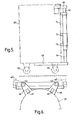
- FIG. 4-10 in which one such modification is made.
- the main lifting/tipping mechanism as described in relation to Figs. 1-3 remains, although parts are omitted from Figs. 4-10 for clarity.
- the same reference numbers are used for the same parts as shown in Figs. 1-3.
- Figs. 4-10 The arrangement of Figs. 4-10 is to enable the mechanism to operate with a form of refuse container consisting of a cylindrical body having dimensions of the order of one metre in diameter and one and a half metres high. Such containers are designed to be lifted by engagement of lifting arms under the container, the upper edge of the container being gripped during lifting.
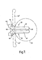
- FIGs. 4-7 there is shown lifting arms or forks 50 for engaging under a cylindrical container 39, the full lines indicating the forks in a lifted position.
- the forks 50 are generally L-shaped each having a horizontally-directed portion 43 and a circular section vertical portion or shaft 44.
- the shafts 44 are each free to rotate and to move axially in bearings 46 located in the horizontal lower cross members 9B of the tipping frame 9.
- the upper ends of the shaft 44 are connected by bearing assemblies 47 to trunnion assemblies 45 which are rigidly mounted on the carriage lift assembly 14.
- the shafts 44 are raised and lowered by vertical movement of the lift carriage, as described in relation to Figs. 1-3, and the portions 43 are raised and lowered with the shafts 44.
- the horizontal portions 43 are movable from the rearwardly-extending full line position (Fig. 7) towards a parked, inoperative position 43'. In the rearwardly-extending position the portions 43 abut each other over surfaces 48 and in the inoperative position 43' over surfaces 49.
- the forks 50 are moved between the inoperative and operative positions manually by means of a linkage (not shown) or, under power, by a piston and cylinder (not shown).
- the tipping frame At the upper end of the tipping frame are mounted two vertical shafts 42 which each rotate and move axially within the vertical legs 9C of the frame 9.
- the upper ends of the shafts 42 each carry a rigidly mounted pick up arm 40 which extends horizontally and which pivotally supports hooks 41.
- the arms 40 can adopt an operative, raised position extending rearwardly (shown in full lines) or a sideways-extending lowered position 40 1 in which the arms are inoperative.
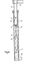
- Fig. 8 shows the means by which each arm 40 is raised, lowered and rotated.
- the shaft 42 locates in a bore of a guide tube 52 mounted in the side member 9C of the frame 9.
- a helical slot 58 is formed at the lower end of the tube 52 and a pin 51 carried on the shaft 42 locates in the slot 58 so that when the shaft 42 is moved along and relative to the tube 52 the shaft also rotates relative to the tube 52.
- the lower end of the shaft 42 carries an abutment ring 54 which abuts the lower end of the tube 52 when the shaft is in its raised position.
- the shaft 42 is moved along the tube 52 by a double-acting piston and cylinder device 56 which at one end is fixed to the shaft 42 by a pin 55 and is secured at its other end to the side frame member 9C by a pivot bracket 57.
- Extension of the piston in the cylinder 56 causes the shaft 42 to cause the arm 40 to rise and move from a lowered position to a raised and rearwardly directed, operative position.
- Figs. 9 and 10 show means for gripping the upper edge of a container 39, such means including a hook 41 having a downwardly-directed tang 41A.
- the hook 41 is pivotally connected to each arm 40 through a pivot 60 and is free to move from a full line position, as shown, to position 41' and is biased towards position 41' by a tension spring 61 which interconnects the hook 41 and the arm 40.
- a top edge of the container 39 is engaged with the hook 41, the hook being moved to the full line position against the spring bias during a container lifting operation.
- the cylinders 56 are then extended to cause the arms 40 to lift and rotate from position 40 1 towards the operative position, the hooks 41 being in position 41 t under the action of the spring 61 to receive the top edge of the container 39.
- the container 39 is mounted on wheels 59 and is pushed towards the lifting/tipping mechanism until a vertical portion 40A of the arms is engaged.
- the cylinder 19 is extended to lift the forks 43 and the forks engage under the base of the container 39 to lift the container until the top edge engages the hooks 41 and causes the hooks to pivot about pivots 60 until further pivoting is prevented by abutment of faces 63.
- the container 39 is now firmly locked between the hooks 41 and the forks 43 and can be tipped, as described in relation to Figs. 1-3, towards the tipped position G" by extension of the cylinders 11. After emptying of the container the container is lowered and released by the reverse procedure.
Landscapes
- Engineering & Computer Science (AREA)
- Mechanical Engineering (AREA)
- Supplying Of Containers To The Packaging Station (AREA)
- Handcart (AREA)
- Refuse-Collection Vehicles (AREA)
- Refuse Collection And Transfer (AREA)
Priority Applications (1)
| Application Number | Priority Date | Filing Date | Title |
|---|---|---|---|
| AT84303946T ATE34361T1 (de) | 1983-06-17 | 1984-06-12 | Vorrichtung zur behandlung von behaeltern. |
Applications Claiming Priority (2)
| Application Number | Priority Date | Filing Date | Title |
|---|---|---|---|
| GB8316592 | 1983-06-17 | ||
| GB838316592A GB8316592D0 (en) | 1983-06-17 | 1983-06-17 | Container handling apparatus |
Publications (2)
| Publication Number | Publication Date |
|---|---|
| EP0129392A1 true EP0129392A1 (de) | 1984-12-27 |
| EP0129392B1 EP0129392B1 (de) | 1988-05-18 |
Family
ID=10544414
Family Applications (1)
| Application Number | Title | Priority Date | Filing Date |
|---|---|---|---|
| EP84303946A Expired EP0129392B1 (de) | 1983-06-17 | 1984-06-12 | Vorrichtung zur Behandlung von Behältern |
Country Status (5)
| Country | Link |
|---|---|
| EP (1) | EP0129392B1 (de) |
| AT (1) | ATE34361T1 (de) |
| DE (1) | DE3471290D1 (de) |
| GB (1) | GB8316592D0 (de) |
| ZA (1) | ZA844434B (de) |
Cited By (3)
| Publication number | Priority date | Publication date | Assignee | Title |
|---|---|---|---|---|
| US4687405A (en) * | 1985-06-24 | 1987-08-18 | Olney David I | Trash can dumping apparatus |
| GB2244467A (en) * | 1990-05-25 | 1991-12-04 | Toter Inc | Lift unit for lifting and emptying waste containers |
| EP0857669A3 (de) * | 1997-02-06 | 1998-08-19 | Hoist Technology Limited | Hubvorrichtung für Müllbehälter |
Families Citing this family (1)
| Publication number | Priority date | Publication date | Assignee | Title |
|---|---|---|---|---|
| DE10221371B4 (de) * | 2002-05-08 | 2005-04-21 | Zöller-Kipper GmbH | Hubkippvorrichtung |
Citations (7)
| Publication number | Priority date | Publication date | Assignee | Title |
|---|---|---|---|---|
| US1763499A (en) * | 1928-10-27 | 1930-06-10 | Joseph Amendolara | Loading apparatus |
| FR51774E (fr) * | 1941-04-08 | 1943-05-03 | Daimler Benz Ag | Dispositif de basculement de bennes pour ordures ménagères déplacé par un agent sous pression |
| FR1020503A (fr) * | 1949-09-26 | 1953-02-06 | Dispositif prévu sur les bennes collectrices d'ordures ménagères en vue de décharger le contenu des poubelles dans ces bennes sans produire de poussière | |
| GB1579830A (en) * | 1977-05-24 | 1980-11-26 | Glover Webb Liversidge Ltd | Raising and tipping mechanism |
| FR2459768A1 (fr) * | 1979-06-26 | 1981-01-16 | Semat | Dispositif de verrouillage des bacs a dechets sur un vehicule de collecte par basculement de ces bacs |
| WO1982001342A1 (en) * | 1980-10-15 | 1982-04-29 | Karlsson Klas | A raisable and lowerable working table or the like |
| GB2092094A (en) * | 1981-01-29 | 1982-08-11 | Hestair Eagle Ltd | Apparatus for tipping bins and refuse containers |
-
1983
- 1983-06-17 GB GB838316592A patent/GB8316592D0/en active Pending
-
1984
- 1984-06-12 AT AT84303946T patent/ATE34361T1/de not_active IP Right Cessation
- 1984-06-12 EP EP84303946A patent/EP0129392B1/de not_active Expired
- 1984-06-12 ZA ZA844434A patent/ZA844434B/xx unknown
- 1984-06-12 DE DE8484303946T patent/DE3471290D1/de not_active Expired
Patent Citations (7)
| Publication number | Priority date | Publication date | Assignee | Title |
|---|---|---|---|---|
| US1763499A (en) * | 1928-10-27 | 1930-06-10 | Joseph Amendolara | Loading apparatus |
| FR51774E (fr) * | 1941-04-08 | 1943-05-03 | Daimler Benz Ag | Dispositif de basculement de bennes pour ordures ménagères déplacé par un agent sous pression |
| FR1020503A (fr) * | 1949-09-26 | 1953-02-06 | Dispositif prévu sur les bennes collectrices d'ordures ménagères en vue de décharger le contenu des poubelles dans ces bennes sans produire de poussière | |
| GB1579830A (en) * | 1977-05-24 | 1980-11-26 | Glover Webb Liversidge Ltd | Raising and tipping mechanism |
| FR2459768A1 (fr) * | 1979-06-26 | 1981-01-16 | Semat | Dispositif de verrouillage des bacs a dechets sur un vehicule de collecte par basculement de ces bacs |
| WO1982001342A1 (en) * | 1980-10-15 | 1982-04-29 | Karlsson Klas | A raisable and lowerable working table or the like |
| GB2092094A (en) * | 1981-01-29 | 1982-08-11 | Hestair Eagle Ltd | Apparatus for tipping bins and refuse containers |
Cited By (3)
| Publication number | Priority date | Publication date | Assignee | Title |
|---|---|---|---|---|
| US4687405A (en) * | 1985-06-24 | 1987-08-18 | Olney David I | Trash can dumping apparatus |
| GB2244467A (en) * | 1990-05-25 | 1991-12-04 | Toter Inc | Lift unit for lifting and emptying waste containers |
| EP0857669A3 (de) * | 1997-02-06 | 1998-08-19 | Hoist Technology Limited | Hubvorrichtung für Müllbehälter |
Also Published As
| Publication number | Publication date |
|---|---|
| ATE34361T1 (de) | 1988-06-15 |
| ZA844434B (en) | 1985-01-30 |
| EP0129392B1 (de) | 1988-05-18 |
| GB8316592D0 (en) | 1983-07-20 |
| DE3471290D1 (en) | 1988-06-23 |
Similar Documents
| Publication | Publication Date | Title |
|---|---|---|
| US4461608A (en) | Rear loader container tipper | |
| US4401407A (en) | Grasping apparatus and collection vehicle | |
| US5484245A (en) | Motor powered intermediate container and method of use | |
| US5064332A (en) | Motor-driven garbage truck comprising a detachable container | |
| US3202305A (en) | Material handling apparatus | |
| US9028193B2 (en) | Adapter to empty rear end load or side load refuse containers into fork borne intermediate container | |
| US5033930A (en) | Garbage collecting truck | |
| US3613924A (en) | Material-handling system | |
| CA2170215C (en) | Tilting bin handler | |
| US4943203A (en) | Retriever truck | |
| US3822802A (en) | Refuse collector | |
| US4978271A (en) | Recycleable material handling apparatus | |
| GB2080757A (en) | Vehicle with lateral equipment for the movement of containers in general | |
| CN104499447B (zh) | 一种用于扫地车的垃圾桶升降系统 | |
| US3458071A (en) | Apparatus for divesting a receptacle of its contents | |
| GB2191461A (en) | Container lifting/tipping mechanism | |
| US6439667B1 (en) | Container dumping apparatus | |
| US5779430A (en) | Material handling system | |
| US5006039A (en) | Method of emptying a container | |
| EP0129392B1 (de) | Vorrichtung zur Behandlung von Behältern | |
| US4948324A (en) | Container emptying apparatus, assembly and method | |
| US2829789A (en) | Load handling apparatus | |
| US2808161A (en) | Refuse truck collecting apparatus | |
| US9505553B2 (en) | Automated load arm mechanism for front forks of refuse collection truck | |
| GB2135963A (en) | Mushroom box tipper |
Legal Events
| Date | Code | Title | Description |
|---|---|---|---|
| PUAI | Public reference made under article 153(3) epc to a published international application that has entered the european phase |
Free format text: ORIGINAL CODE: 0009012 |
|
| AK | Designated contracting states |
Designated state(s): AT BE CH DE FR GB IT LI LU NL SE |
|
| 17P | Request for examination filed |
Effective date: 19850614 |
|
| GRAA | (expected) grant |
Free format text: ORIGINAL CODE: 0009210 |
|
| AK | Designated contracting states |
Kind code of ref document: B1 Designated state(s): AT BE CH DE FR GB IT LI LU NL SE |
|
| PG25 | Lapsed in a contracting state [announced via postgrant information from national office to epo] |
Ref country code: NL Effective date: 19880518 Ref country code: LI Effective date: 19880518 Ref country code: IT Free format text: LAPSE BECAUSE OF FAILURE TO SUBMIT A TRANSLATION OF THE DESCRIPTION OR TO PAY THE FEE WITHIN THE PRESCRIBED TIME-LIMIT;WARNING: LAPSES OF ITALIAN PATENTS WITH EFFECTIVE DATE BEFORE 2007 MAY HAVE OCCURRED AT ANY TIME BEFORE 2007. THE CORRECT EFFECTIVE DATE MAY BE DIFFERENT FROM THE ONE RECORDED. Effective date: 19880518 Ref country code: CH Effective date: 19880518 Ref country code: BE Effective date: 19880518 Ref country code: AT Effective date: 19880518 |
|
| REF | Corresponds to: |
Ref document number: 34361 Country of ref document: AT Date of ref document: 19880615 Kind code of ref document: T |
|
| PG25 | Lapsed in a contracting state [announced via postgrant information from national office to epo] |
Ref country code: SE Effective date: 19880531 |
|
| REF | Corresponds to: |
Ref document number: 3471290 Country of ref document: DE Date of ref document: 19880623 |
|
| ET | Fr: translation filed | ||
| PG25 | Lapsed in a contracting state [announced via postgrant information from national office to epo] |
Ref country code: LU Free format text: LAPSE BECAUSE OF NON-PAYMENT OF DUE FEES Effective date: 19880630 |
|
| REG | Reference to a national code |
Ref country code: CH Ref legal event code: PL |
|
| NLV1 | Nl: lapsed or annulled due to failure to fulfill the requirements of art. 29p and 29m of the patents act | ||
| PLBE | No opposition filed within time limit |
Free format text: ORIGINAL CODE: 0009261 |
|
| STAA | Information on the status of an ep patent application or granted ep patent |
Free format text: STATUS: NO OPPOSITION FILED WITHIN TIME LIMIT |
|
| 26N | No opposition filed | ||
| PGFP | Annual fee paid to national office [announced via postgrant information from national office to epo] |
Ref country code: GB Payment date: 19910531 Year of fee payment: 8 |
|
| PGFP | Annual fee paid to national office [announced via postgrant information from national office to epo] |
Ref country code: FR Payment date: 19910619 Year of fee payment: 8 |
|
| PGFP | Annual fee paid to national office [announced via postgrant information from national office to epo] |
Ref country code: DE Payment date: 19910628 Year of fee payment: 8 |
|
| PG25 | Lapsed in a contracting state [announced via postgrant information from national office to epo] |
Ref country code: GB Effective date: 19920612 |
|
| GBPC | Gb: european patent ceased through non-payment of renewal fee |
Effective date: 19920612 |
|
| PG25 | Lapsed in a contracting state [announced via postgrant information from national office to epo] |
Ref country code: FR Effective date: 19930226 |
|
| PG25 | Lapsed in a contracting state [announced via postgrant information from national office to epo] |
Ref country code: DE Effective date: 19930302 |
|
| REG | Reference to a national code |
Ref country code: FR Ref legal event code: ST |