EP0129410A2 - Valve de retenue - Google Patents
Valve de retenue Download PDFInfo
- Publication number
- EP0129410A2 EP0129410A2 EP84304011A EP84304011A EP0129410A2 EP 0129410 A2 EP0129410 A2 EP 0129410A2 EP 84304011 A EP84304011 A EP 84304011A EP 84304011 A EP84304011 A EP 84304011A EP 0129410 A2 EP0129410 A2 EP 0129410A2
- Authority
- EP
- European Patent Office
- Prior art keywords
- disk
- housing
- seat
- check valve
- backflow check
- Prior art date
- Legal status (The legal status is an assumption and is not a legal conclusion. Google has not performed a legal analysis and makes no representation as to the accuracy of the status listed.)
- Granted
Links
- 239000012530 fluid Substances 0.000 claims abstract description 29
- 239000000463 material Substances 0.000 claims description 6
- 239000004033 plastic Substances 0.000 claims description 4
- 229920003023 plastic Polymers 0.000 claims description 4
- 238000007789 sealing Methods 0.000 description 5
- 238000001990 intravenous administration Methods 0.000 description 4
- 230000001788 irregular Effects 0.000 description 2
- BVKZGUZCCUSVTD-UHFFFAOYSA-L Carbonate Chemical compound [O-]C([O-])=O BVKZGUZCCUSVTD-UHFFFAOYSA-L 0.000 description 1
- 230000007423 decrease Effects 0.000 description 1
- 239000007789 gas Substances 0.000 description 1
- 238000007373 indentation Methods 0.000 description 1
- 239000007788 liquid Substances 0.000 description 1
- 230000007257 malfunction Effects 0.000 description 1
- 229920000642 polymer Polymers 0.000 description 1
- 230000002265 prevention Effects 0.000 description 1
- 229920002379 silicone rubber Polymers 0.000 description 1
- 239000004945 silicone rubber Substances 0.000 description 1
- 229920001169 thermoplastic Polymers 0.000 description 1
- 239000004416 thermosoftening plastic Substances 0.000 description 1
- 238000003466 welding Methods 0.000 description 1
Images
Classifications
-
- A—HUMAN NECESSITIES
- A61—MEDICAL OR VETERINARY SCIENCE; HYGIENE
- A61M—DEVICES FOR INTRODUCING MEDIA INTO, OR ONTO, THE BODY; DEVICES FOR TRANSDUCING BODY MEDIA OR FOR TAKING MEDIA FROM THE BODY; DEVICES FOR PRODUCING OR ENDING SLEEP OR STUPOR
- A61M39/00—Tubes, tube connectors, tube couplings, valves, access sites or the like, specially adapted for medical use
- A61M39/22—Valves or arrangement of valves
- A61M39/24—Check- or non-return valves
-
- F—MECHANICAL ENGINEERING; LIGHTING; HEATING; WEAPONS; BLASTING
- F16—ENGINEERING ELEMENTS AND UNITS; GENERAL MEASURES FOR PRODUCING AND MAINTAINING EFFECTIVE FUNCTIONING OF MACHINES OR INSTALLATIONS; THERMAL INSULATION IN GENERAL
- F16K—VALVES; TAPS; COCKS; ACTUATING-FLOATS; DEVICES FOR VENTING OR AERATING
- F16K15/00—Check valves
- F16K15/14—Check valves with flexible valve members
- F16K15/141—Check valves with flexible valve members the closure elements not being fixed to the valve body
-
- A—HUMAN NECESSITIES
- A61—MEDICAL OR VETERINARY SCIENCE; HYGIENE
- A61M—DEVICES FOR INTRODUCING MEDIA INTO, OR ONTO, THE BODY; DEVICES FOR TRANSDUCING BODY MEDIA OR FOR TAKING MEDIA FROM THE BODY; DEVICES FOR PRODUCING OR ENDING SLEEP OR STUPOR
- A61M39/00—Tubes, tube connectors, tube couplings, valves, access sites or the like, specially adapted for medical use
- A61M39/22—Valves or arrangement of valves
- A61M39/24—Check- or non-return valves
- A61M2039/242—Check- or non-return valves designed to open when a predetermined pressure or flow rate has been reached, e.g. check valve actuated by fluid
-
- A—HUMAN NECESSITIES
- A61—MEDICAL OR VETERINARY SCIENCE; HYGIENE
- A61M—DEVICES FOR INTRODUCING MEDIA INTO, OR ONTO, THE BODY; DEVICES FOR TRANSDUCING BODY MEDIA OR FOR TAKING MEDIA FROM THE BODY; DEVICES FOR PRODUCING OR ENDING SLEEP OR STUPOR
- A61M39/00—Tubes, tube connectors, tube couplings, valves, access sites or the like, specially adapted for medical use
- A61M39/22—Valves or arrangement of valves
- A61M39/24—Check- or non-return valves
- A61M2039/2433—Valve comprising a resilient or deformable element, e.g. flap valve, deformable disc
- A61M2039/2446—Flexible disc
- A61M2039/2466—Flexible disc being fixed in its center
-
- Y—GENERAL TAGGING OF NEW TECHNOLOGICAL DEVELOPMENTS; GENERAL TAGGING OF CROSS-SECTIONAL TECHNOLOGIES SPANNING OVER SEVERAL SECTIONS OF THE IPC; TECHNICAL SUBJECTS COVERED BY FORMER USPC CROSS-REFERENCE ART COLLECTIONS [XRACs] AND DIGESTS
- Y10—TECHNICAL SUBJECTS COVERED BY FORMER USPC
- Y10T—TECHNICAL SUBJECTS COVERED BY FORMER US CLASSIFICATION
- Y10T137/00—Fluid handling
- Y10T137/7722—Line condition change responsive valves
- Y10T137/7837—Direct response valves [i.e., check valve type]
- Y10T137/7879—Resilient material valve
Definitions
- This invention is directed to a backflow check valve which is particularly, but not exclusively, suitable for use with an intravenous (IV) administration set.
- IV intravenous
- valve member As a result, some inventors have focused upon certain spatial relationships between the valve member and the sealing surface or valve seat. For example, in US 3 889 710 it was thought essential that an abutment means be spaced from the sealing surface by more than '-the thickness of a disk. In US 4 354 492 another inventor thought it necessary that the valve member or disk against the valve seat be free of mechanical bias. In US 4 286 628 yet another inventor thought it necessary to employ prongs to pre-bias a flexible disk against a ring seat, whereby flow check is achieved by engagement of the disk against a convex shoulder of the seat. For a variety of reasons, such backflow check valves also develop problems in IV use and must be replaced.
- a backflow check valve comprises: a housing having a fluid inlet and a fluid outlet; a biasable disk carried within said housing for controlling fluid flow through said housing; and a valve seat carried by said housing against which said disk is biasably urged; characterised in that said housing carries first and second disk-biasing means for engaging opposite sides of said disk in such a manner that said disk is engaged along a first pair of spaced opposite portions thereof and said disk is engageable with said seat along a second pair of spaced opposite portions thereof intermediate said first pair of disk portions for precluding backflow of fluid through said housing.
- said seat has an annular non-planar disk-engageable surface, and said disk is clamped to said seat along said first pair of disk portions, but the disk is not necessarily circular.
- Said first disk-biasing means may have an edge formed from two intersecting planar surfaces, and said second disk-biasing means may have a depression into which said edge is insertable so that said disk is sandwiched between said edge and said depression.
- said seat has a concave cylindrical disk-engageable surface defining a valley whose nadir forms said depression; said housing carries alignment means for aligning said edge with said depression; and said housing carries centering means for centering said disk with respect to said seat.
- Said housing may include a female portion having a cavity, and may further include a male portion having a projection insertable into said cavity, said female portion and said male portion locating said disk therebetween in an attitude generally transverse to a preselected direction of fluid flow through said housing.
- said female portion and said male portion are removably coupled to one another; and said female portion is integrally formed of a plastics material with said fluid inlet and said seat, said male portion is integrally formed of a plastics material with said fluid outlet and said projection, and said disk is integrally formed as a thin circular member of resiliently deformable material.
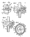
- a backflow check valve 20 in accordance with the present invention comprises a housing 22 and a valve member in the form of a disk 24 ( Figure 2).
- the housing 22 preferably includes a cup or female portion 26 and a cover or male portion 28 having an integral projection or blade 30 insertable into the cup 26.
- the female and male housing portions 26, 28 are both preferably circular in cross section ( Figures 4 and 8).
- the male portion 28 includes a centrally aligned (Fig. 11) and axially disposed (Figs. 9 and 10) integral conduit 32 for obtaining substantially axial flow of fluid through the male portion 28.
- Circumferentially surrounding the conduit 32 and formed within the male housing portion 28 is an annular slot or recess 33 having an irregular floor (Figs. 9 and 10).
- the conduit 32 preferably has a slight taper such that the outside diameter of the conduit 32 decreases progressively further away from the recess 33.
- the female-portion 26 also preferably includes a centrally arranged (Fig. 7) and axially disposed (Figs. 5 and 6) integral conduit 34 for obtaining substantially axial flow of fluid through the female portion 26.
- the female portion 26 further includes an integral seat 36 (Figs. 4-6) against which the disk 24 is urgeable (Fig. 2).
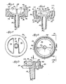
- the female portion 26 also preferably includes a first recess or counterboze 38 intermediate the seat 36 and the conduit 34, and a second recess or cavity 40.
- the first recess or counterbore 38 is defined by a vertical sidewall 42 and a horizontally disposed curved surface or floor 44 (Fig. 6), both of which are integral with the female portion 26.
- the male portion 28 covers the cavity 40 (Figs. 2,3).
- An upper surface of the cup 26 includes an annular slot 43 (Fig. 4), preferably triangular in cross section (Figs. 5,6); and the lower surface of the cover 28 includes a depending integral annular projection 45 (Figs. 8-10) which is readily insertable into and which fits snugly in the cup slot 43 (Figs. 2,3) for covering the cavity 40 in a fluid-tight manner.
- the seat 36 and the surface or floor 44 are curved surfaces having irregular floors, each respectively preferably describing a cylindrical section having a depression disposed transverse to an axis 46 (Figs. 5, 6) of the female portion 26.
- the seat 36 preferably has a nadir 48 (Figs. 4,6); and the surface or floor 44 also preferably has seat nadir 50 (Fig. 4), but which is in a different plane (Fig. 6).
- An edge 52 of the blade 30 is preferably formed from an intersection of two planar surfaces 54 (Figs. 8-10).
- the blade edge 52 is preferably disposed transverse to an axis 56 of the male portion 28 (Fig. 9).
- the second recess or cavity 40 (of the female portion 26) is defined by the seat 36 and a second vertical sidewall 58 (Figs. 4-6).
- the first and second vertical sidewalls 42, 58 are preferably concentric to each other and to the conduit 34 (Fig. 4).
- the female portion 26 also preferably includes ribs 60 integral with and radially inwardly projecting from the sidewall 58 (Fig. 4).
- the ribs 60 are axially disposed (Fig. 5) and oppositely spaced (Fig. 4) along the periphery of the sidewall 58.
- the blade 30 preferably includes indentations 62 (Figs. 8-10) axially disposed and oppositely spaced along the blade outer periphery for aligning the blade edge 52 with the nadir 48 of the seat 36.
- the sidewall 58 (of the female portion 26) further includes a pair of integral projections 64 (Figs. 4-6), one projection 64 being arranged on the sidewall 58 opposite the other projection 64 (Fig. 4), the projections 64 being intermediate the ribs 60.
- Each such projection 64 is defined by a planar surface 66, which is spaced from the axis 4 6 (Figs. 5,6), and an inclined, segmental surface 68 which is disposed inwardly toward the cavity 40.
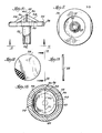
- the underside of the female portion 26 preferably includes a first integral rib 70 (Figs. 5,7), radially disposed about the conduit 34, and a second integral rib 72, integral with the first rib 70 (Fig. 7), disposed transverse to the axis 46 (Fig. 6).
- the second rib 72 is integral with the conduit 34 and thereby provides structural support for the conduit 34 of the female portion 26.
- the underside of the female portion 26 also includes two recesses 74 which are oppositely spaced from the conduit 34 (Fig. 7).
- Each of the recesses 74 preferably has a curvature defining a cylindrical section having a zenith 75 disposed transverse to the axis 46 (Figs. 6, 7).
- the disk 24 is preferably circular in cross section ( F ig. 12).
- the disk 24 is relatively thin (Fig. 13); and is biasable and resilient.
- the preferred disk 24 is made of silicone rubber.
- the diameter of the disk 24 is such that when the disk 24 is urged against the seat 36 by the blade edge 52 (Fig. 2), the edge 52 contacting one side of the disk 24 to be urged against and to biasly engage the seat 36 along the seat nadir 48, and the curvature of the seat 36 causes the disk 24 to be biasly engaged by the seat 36 at spaced opposite end portions 77 (Fig. 14) of the disk 24.
- Such a biased engagement produces a uniform biasing in the disk 24 along the seat nadir 48 and transverse to the seat nadir 48 to thereby minimize shear stress in the disk 24. This is particularly important if low flow rates are desired. Since the disk is less stressed it allows very small amounts of fluid to flow through the valve. The disc can deflect more easily when held along a diameter than if biased into a partially spherical shape.
- the distance between the interface of the male and female portions of the housing and the outer portions of the blade edge 52 is such that at least a portion of the blade edge clampingly engages and constantly squeezes outer portions the disk against the seat nadir 48.
- This clamping engagement may be very slight, but is important to assure that the disk is not free to slide to different positions on the valve seat 36.
- Preferred direction of flow through the check valve 20 is into the conduit 34, through the first recess 38 and second recess 40 (fluid flow causing portions of the disk 24 . to be lifted away from the seat 36) and out of the check valve 20 via the conduit 32 (Fig. 2).
- the disk 24, oppositely biasly engaged between the blade edge 52 and seat nadir 48 is positively positioned and thus preferably does not collapse into the recess 38.
- the prevention of collapse of the disk 24 into the recess 38 is aided by the fact that. the disk is clamped between the blade edge 52 and the nadir 48.
- the disk 24 is axially urged (preferably along a diameter thereof) by the blade 30 (not shown) against the nadir 48 of the seat 36.
- the seat nadir 48 and axis 46 define a plane. A line perpendicular to this plane and passing through a point on the surface of the seat 36 defines a minimal distance from such point to the plane. Because the seat 36 . is preferably a portion of a cylindrical section, the axial (Fig. 6) and radial (Fig.
- curvature of the seat 36 causes the seat 36 to exert an increasingly biased pressure upon the underside of the disk 24 as this minimal dimension increases to a maximum at the disk end portions 77 (Fig. 14).
- This feature of the present invention insures leakless sealing of the disk 24 against the seat 36 for backflow check.
- the disk 24 is respectively engaged on opposite sides by the blade edge 52 and seat nadir 48, it is not free to move axially; nor is the disk 24 free to move radially (relative to the axes 46, 56) within the housing 22.
- the elastomeric properties of the disk 24 are such that fluid flow, as above described, causes portions of the disk 24 to be lifted away from the seat 36; and the disk elastomeric and resiliency properties preferably do not prevent relatively small quantities of fluid from flowing from the first recess 38 into the second recess 40.
- the ribs 60 and projections 64 preferably center (Fig. 4) the disk 24 in the recess or cavity 40, and preferably initially engage the disk 24. Engagement by the blade edge 52 (for causing the disk 24 to engage the seat 36) preferably causes the disk end portion 77 to be drawn away from the projections 64 approximately equally (Fig 14). In the absence of fluid flow through the housing 22, upper and lower end portions of a diameter of the disk 24 are engaged by the blade edge 52 and the seat nadir 48 respectively, and the end portions 77, which are oppositely spaced from such diameter of the disk 24 are preferably engaged along an underside thereof by the seat 36.
- the check valve 20 is capable of relatively high flow rate (in relation to free volume, available for fluid, within the housing 22). Moreover, because the blade 30 occupies a substantial portion of the second recess 40.and because the second recess 40 is relatively much greater in volume than the first recess 38, the volume of fluid needed to prime the check valve 20 is relatively low.
- the housing 22 is preferably made of a commercially available molded thermoplastic carbonate-linked polymer.
- the female and male portions 26, 28 are preferably permanently secured together, such as by ultrasonic welding. Yet, it can be appreciated that, if desired, the female and male portions 26, 28 can be screwed together so that the disk 24 can be removed from the check valve 20 and another disk (not shown) having properties different from the disk 24 described above can be inserted in the check valve 20 for modifying fluid flow properties of the check valve 20.
- the cover 28 and cup 26 can, for example, accordingly respectively include meshing, integral, fluid-tight threaded portions for covering the cavity 40 in a fluid-tight manner.
- backflow check valve of the present invention has been disclosed as preferably being used in combination with IV administration sets, it can be appreciated, by those skilled in the art, that the present invention is generally useful as a check valve in a variety of applications (such as, for example, flow of liquids or gases) where backflow check is required.
Landscapes
- Engineering & Computer Science (AREA)
- Health & Medical Sciences (AREA)
- Heart & Thoracic Surgery (AREA)
- General Engineering & Computer Science (AREA)
- Hematology (AREA)
- Pulmonology (AREA)
- Anesthesiology (AREA)
- Biomedical Technology (AREA)
- Mechanical Engineering (AREA)
- Life Sciences & Earth Sciences (AREA)
- Animal Behavior & Ethology (AREA)
- General Health & Medical Sciences (AREA)
- Public Health (AREA)
- Veterinary Medicine (AREA)
- Check Valves (AREA)
- Infusion, Injection, And Reservoir Apparatuses (AREA)
Applications Claiming Priority (2)
| Application Number | Priority Date | Filing Date | Title |
|---|---|---|---|
| US06/505,501 US4765372A (en) | 1983-06-17 | 1983-06-17 | Check valve |
| US505501 | 2000-02-17 |
Publications (3)
| Publication Number | Publication Date |
|---|---|
| EP0129410A2 true EP0129410A2 (fr) | 1984-12-27 |
| EP0129410A3 EP0129410A3 (en) | 1987-04-15 |
| EP0129410B1 EP0129410B1 (fr) | 1989-10-11 |
Family
ID=24010563
Family Applications (1)
| Application Number | Title | Priority Date | Filing Date |
|---|---|---|---|
| EP84304011A Expired EP0129410B1 (fr) | 1983-06-17 | 1984-06-14 | Valve de retenue |
Country Status (6)
| Country | Link |
|---|---|
| US (1) | US4765372A (fr) |
| EP (1) | EP0129410B1 (fr) |
| JP (1) | JPS604680A (fr) |
| AU (1) | AU2599984A (fr) |
| CA (1) | CA1235978A (fr) |
| DE (1) | DE3480110D1 (fr) |
Cited By (6)
| Publication number | Priority date | Publication date | Assignee | Title |
|---|---|---|---|---|
| GB2191271A (en) * | 1986-05-23 | 1987-12-09 | Halkey Roberts Corp | Improvements in or relating to check valves |
| EP0276556A1 (fr) * | 1987-01-22 | 1988-08-03 | Filtertek, Inc. | Clapet antiretour à écoulement central |
| US4966199A (en) * | 1989-06-08 | 1990-10-30 | Filtertek, Inc. | Diaphragm-type center flow check valve |
| WO1992012371A1 (fr) * | 1991-01-08 | 1992-07-23 | Denley Instruments Limited | Clapet de non-retour |
| DE19545452C1 (de) * | 1995-12-06 | 1996-11-14 | Thomas Michael Jokisch | Rückschlagventil für Fluide mit geringen Druckunterschieden, insbesondere für die Medizintechnik und Aquaristik |
| WO2014107436A1 (fr) * | 2013-01-02 | 2014-07-10 | Illinois Tool Works Inc. | Clapet antiretour à filtre intégré |
Families Citing this family (22)
| Publication number | Priority date | Publication date | Assignee | Title |
|---|---|---|---|---|
| US4934362A (en) * | 1987-03-26 | 1990-06-19 | Minnesota Mining And Manufacturing Company | Unidirectional fluid valve |
| US5014739A (en) * | 1989-10-10 | 1991-05-14 | Ced's, Inc. | Check valve assembly |
| US5218993A (en) * | 1992-06-01 | 1993-06-15 | Wagner Spray Tech Corporation | Serviceable check valve |
| US5405333A (en) * | 1992-12-28 | 1995-04-11 | Richmond; Frank M. | Liquid medicament bag with needleless connector fitting using boat assembly |
| US6206860B1 (en) | 1993-07-28 | 2001-03-27 | Frank M. Richmond | Spikeless connection and drip chamber with valve |
| US5618268A (en) * | 1995-06-06 | 1997-04-08 | B. Braun Medical Inc. | Medical infusion devices and medicine delivery systems employing the same |
| US5623969A (en) * | 1995-06-07 | 1997-04-29 | B. Braun Medical Inc. | Normally closed aspiration valve |
| DE19746239B4 (de) * | 1996-11-02 | 2010-06-02 | Volkswagen Ag | Anordnung eines Ventiles an einem Hohlkörper |
| US6106502A (en) * | 1996-12-18 | 2000-08-22 | Richmond; Frank M. | IV sets with needleless fittings and valves |
| US6021961A (en) * | 1998-03-06 | 2000-02-08 | Flexible Products Company | Crossover-resistant plural component mixing nozzle |
| KR100421524B1 (ko) * | 2001-11-16 | 2004-03-18 | 연우인더스트리(주) | 주사 수액 역류방지 장치 |
| US7438090B2 (en) * | 2005-01-06 | 2008-10-21 | Dynamic Air Inc. | Booster valve |
| US20080308166A1 (en) * | 2005-10-20 | 2008-12-18 | Richmond Frank M | Connector/Device with Reflux Valves |
| JP5273473B2 (ja) * | 2008-09-12 | 2013-08-28 | 株式会社ジェイ・エム・エス | 注出口及び注出口付き液体収容体 |
| US8539712B2 (en) * | 2008-09-26 | 2013-09-24 | University Of Vermont And State Agricultural College | Maple syrup production spout assembly with backflow check valve |
| US20100170152A1 (en) * | 2008-09-26 | 2010-07-08 | University Of Vermont And State Agricultural College | Maple spout with interior chamber and maple syrup production system using same |
| JP5310731B2 (ja) * | 2008-10-16 | 2013-10-09 | 株式会社ジェイ・エム・エス | 注出口及び注出口付き液体収容体 |
| US10226614B2 (en) * | 2009-03-19 | 2019-03-12 | Illinois Tool Works Inc. | One-way check valve |
| US8424242B2 (en) * | 2010-01-19 | 2013-04-23 | University Of Vermont And State Agricultural College | Dual-line spout and maple syrup production system using same |
| US11554471B2 (en) * | 2014-08-28 | 2023-01-17 | Power Tech Staple and Nail, Inc. | Elastomeric exhaust reed valve for combustion driven fastener hand tool |
| CN105056383A (zh) * | 2015-08-10 | 2015-11-18 | 安徽省天康医疗用品有限公司 | 一种医疗输液用防回流阀 |
| US20220305193A1 (en) * | 2021-03-29 | 2022-09-29 | Biosense Webster (Israel) Ltd. | In-flow control for passively irrigated electrophysiology devices |
Family Cites Families (11)
| Publication number | Priority date | Publication date | Assignee | Title |
|---|---|---|---|---|
| US2292003A (en) * | 1939-10-12 | 1942-08-04 | Mine Safety Appliances Co | Valve |
| US3807445A (en) * | 1972-06-19 | 1974-04-30 | American Hospital Supply Corp | Audible pressure relief valve for medical humidifier |
| US3889710A (en) * | 1972-11-07 | 1975-06-17 | Julien H Brost | Check valve with elastomeric valve element |
| US3954121A (en) * | 1975-03-17 | 1976-05-04 | The Weatherhead Company | Vent check valve |
| US4210173A (en) * | 1976-12-06 | 1980-07-01 | American Hospital Supply Corporation | Syringe pumping system with valves |
| US4181146A (en) * | 1977-07-21 | 1980-01-01 | Luigi Goglio | Two-way valve closing at balanced pressure condition |
| DE2803778A1 (de) * | 1978-01-28 | 1979-08-02 | Freudenberg Carl Fa | Rueckschlagventil |
| US4222407A (en) * | 1978-09-13 | 1980-09-16 | Baxter Travenol Laboratories, Inc. | One-way flex valve |
| US4354492A (en) * | 1979-04-16 | 1982-10-19 | American Hospital Supply Corporation | Medical administration set with backflow check valve |
| US4286628A (en) * | 1979-06-21 | 1981-09-01 | Nypro, Inc. | Control of fluid flow using longitudinally movable disc |
| US4415003A (en) * | 1981-02-18 | 1983-11-15 | Nypro Inc. | Control of fluid flow using a flexible disc |
-
1983
- 1983-06-17 US US06/505,501 patent/US4765372A/en not_active Expired - Fee Related
-
1984
- 1984-03-09 CA CA000449241A patent/CA1235978A/fr not_active Expired
- 1984-03-22 AU AU25999/84A patent/AU2599984A/en not_active Abandoned
- 1984-05-14 JP JP59094767A patent/JPS604680A/ja active Pending
- 1984-06-14 DE DE8484304011T patent/DE3480110D1/de not_active Expired
- 1984-06-14 EP EP84304011A patent/EP0129410B1/fr not_active Expired
Cited By (9)
| Publication number | Priority date | Publication date | Assignee | Title |
|---|---|---|---|---|
| GB2191271A (en) * | 1986-05-23 | 1987-12-09 | Halkey Roberts Corp | Improvements in or relating to check valves |
| GB2191271B (en) * | 1986-05-23 | 1990-05-16 | Halkey Roberts Corp | Improvements in or relating to check valves |
| EP0276556A1 (fr) * | 1987-01-22 | 1988-08-03 | Filtertek, Inc. | Clapet antiretour à écoulement central |
| US4966199A (en) * | 1989-06-08 | 1990-10-30 | Filtertek, Inc. | Diaphragm-type center flow check valve |
| WO1992012371A1 (fr) * | 1991-01-08 | 1992-07-23 | Denley Instruments Limited | Clapet de non-retour |
| DE19545452C1 (de) * | 1995-12-06 | 1996-11-14 | Thomas Michael Jokisch | Rückschlagventil für Fluide mit geringen Druckunterschieden, insbesondere für die Medizintechnik und Aquaristik |
| WO2014107436A1 (fr) * | 2013-01-02 | 2014-07-10 | Illinois Tool Works Inc. | Clapet antiretour à filtre intégré |
| CN104797280A (zh) * | 2013-01-02 | 2015-07-22 | 伊利诺斯工具制品有限公司 | 带有一体的过滤器的止回阀 |
| US9421354B2 (en) | 2013-01-02 | 2016-08-23 | Illinois Tool Works Inc. | Check valve with integrated filter |
Also Published As
| Publication number | Publication date |
|---|---|
| DE3480110D1 (en) | 1989-11-16 |
| US4765372A (en) | 1988-08-23 |
| AU2599984A (en) | 1984-12-20 |
| CA1235978A (fr) | 1988-05-03 |
| EP0129410B1 (fr) | 1989-10-11 |
| JPS604680A (ja) | 1985-01-11 |
| EP0129410A3 (en) | 1987-04-15 |
Similar Documents
| Publication | Publication Date | Title |
|---|---|---|
| EP0129410B1 (fr) | Valve de retenue | |
| EP1125074B1 (fr) | Clapet antiretour de type disque | |
| EP0452045B1 (fr) | Soupape à bec de canard, normalement fermée | |
| US5771935A (en) | Check valve, especially for the medical technique | |
| US4369812A (en) | Control of fluid flow using precisely positioned disc | |
| CA2582499C (fr) | Clapet de non retour bombe | |
| EP1099457B1 (fr) | Clapet anti-retour pour tubes de perfusion ou similaire | |
| US4161291A (en) | Emitter | |
| TW480184B (en) | Anti-siphon valve for medical infusion lines and the like | |
| JP2735951B2 (ja) | 実用的逆止弁 | |
| JPH0261675B2 (fr) | ||
| US5803112A (en) | Reflux valve means | |
| WO1989012267A1 (fr) | Regulateur de contre-pression | |
| US6959725B2 (en) | Constant pressure regulator | |
| US5857486A (en) | Pressure relief or back pressure valve | |
| AU624842B2 (en) | One way flow valve | |
| US4610275A (en) | Valve for relieving pressure or checking reverse flow | |
| EP3368143B1 (fr) | Dispositif de régulation du débit | |
| US5692539A (en) | Check valve for liquids | |
| US20070131296A1 (en) | Flow restrictor device for a medical apparatus | |
| WO1992012371A1 (fr) | Clapet de non-retour | |
| JPS61149674A (ja) | 逆止弁 | |
| US20240427358A1 (en) | Multi-orifice back pressure regulator with seal enhanced positive shut-off | |
| KR900015764A (ko) | 수액세트 또는 수혈세트에 사용되는 유량 조정기 | |
| CA2045991A1 (fr) | Clapet de retenue pouvant etre utilise avec de la boue de particules |
Legal Events
| Date | Code | Title | Description |
|---|---|---|---|
| PUAI | Public reference made under article 153(3) epc to a published international application that has entered the european phase |
Free format text: ORIGINAL CODE: 0009012 |
|
| AK | Designated contracting states |
Designated state(s): DE FR GB SE |
|
| PUAL | Search report despatched |
Free format text: ORIGINAL CODE: 0009013 |
|
| AK | Designated contracting states |
Kind code of ref document: A3 Designated state(s): DE FR GB SE |
|
| 17P | Request for examination filed |
Effective date: 19870904 |
|
| 17Q | First examination report despatched |
Effective date: 19880502 |
|
| GRAA | (expected) grant |
Free format text: ORIGINAL CODE: 0009210 |
|
| AK | Designated contracting states |
Kind code of ref document: B1 Designated state(s): DE FR GB SE |
|
| REF | Corresponds to: |
Ref document number: 3480110 Country of ref document: DE Date of ref document: 19891116 |
|
| ET | Fr: translation filed | ||
| PGFP | Annual fee paid to national office [announced via postgrant information from national office to epo] |
Ref country code: FR Payment date: 19900517 Year of fee payment: 7 |
|
| PGFP | Annual fee paid to national office [announced via postgrant information from national office to epo] |
Ref country code: DE Payment date: 19900521 Year of fee payment: 7 |
|
| PGFP | Annual fee paid to national office [announced via postgrant information from national office to epo] |
Ref country code: SE Payment date: 19900522 Year of fee payment: 7 |
|
| PGFP | Annual fee paid to national office [announced via postgrant information from national office to epo] |
Ref country code: GB Payment date: 19900601 Year of fee payment: 7 |
|
| PLBE | No opposition filed within time limit |
Free format text: ORIGINAL CODE: 0009261 |
|
| STAA | Information on the status of an ep patent application or granted ep patent |
Free format text: STATUS: NO OPPOSITION FILED WITHIN TIME LIMIT |
|
| 26N | No opposition filed | ||
| PG25 | Lapsed in a contracting state [announced via postgrant information from national office to epo] |
Ref country code: GB Effective date: 19910614 |
|
| PG25 | Lapsed in a contracting state [announced via postgrant information from national office to epo] |
Ref country code: SE Effective date: 19910615 |
|
| GBPC | Gb: european patent ceased through non-payment of renewal fee | ||
| PG25 | Lapsed in a contracting state [announced via postgrant information from national office to epo] |
Ref country code: FR Effective date: 19920228 |
|
| PG25 | Lapsed in a contracting state [announced via postgrant information from national office to epo] |
Ref country code: DE Effective date: 19920401 |
|
| REG | Reference to a national code |
Ref country code: FR Ref legal event code: ST |
|
| EUG | Se: european patent has lapsed |
Ref document number: 84304011.4 Effective date: 19920109 |