EP0129438A2 - Flexibler elektrischer Freileiter - Google Patents
Flexibler elektrischer Freileiter Download PDFInfo
- Publication number
- EP0129438A2 EP0129438A2 EP84304103A EP84304103A EP0129438A2 EP 0129438 A2 EP0129438 A2 EP 0129438A2 EP 84304103 A EP84304103 A EP 84304103A EP 84304103 A EP84304103 A EP 84304103A EP 0129438 A2 EP0129438 A2 EP 0129438A2
- Authority
- EP
- European Patent Office
- Prior art keywords
- ribbon structure
- elongate
- undulating
- optical fibre
- flexible conductor
- Prior art date
- Legal status (The legal status is an assumption and is not a legal conclusion. Google has not performed a legal analysis and makes no representation as to the accuracy of the status listed.)
- Granted
Links
- 239000004020 conductor Substances 0.000 title claims abstract description 54
- 239000013307 optical fiber Substances 0.000 claims abstract description 37
- 230000003287 optical effect Effects 0.000 claims abstract description 19
- 230000003014 reinforcing effect Effects 0.000 claims abstract description 16
- 239000012858 resilient material Substances 0.000 claims abstract description 7
- 239000004033 plastic Substances 0.000 claims abstract description 6
- 229920003023 plastic Polymers 0.000 claims abstract description 6
- 239000000463 material Substances 0.000 claims abstract description 5
- 230000005540 biological transmission Effects 0.000 claims abstract 2
- 239000004411 aluminium Substances 0.000 claims description 19
- 229910052782 aluminium Inorganic materials 0.000 claims description 19
- XAGFODPZIPBFFR-UHFFFAOYSA-N aluminium Chemical compound [Al] XAGFODPZIPBFFR-UHFFFAOYSA-N 0.000 claims description 19
- 229910052751 metal Inorganic materials 0.000 claims description 13
- 239000002184 metal Substances 0.000 claims description 13
- 229910001092 metal group alloy Inorganic materials 0.000 claims description 13
- 229910045601 alloy Inorganic materials 0.000 claims description 10
- 239000000956 alloy Substances 0.000 claims description 10
- 229910000831 Steel Inorganic materials 0.000 claims description 6
- 229920001296 polysiloxane Polymers 0.000 claims description 6
- 239000010959 steel Substances 0.000 claims description 6
- 239000007787 solid Substances 0.000 claims description 2
- -1 polyethylene terephthalate Polymers 0.000 description 8
- 229920000139 polyethylene terephthalate Polymers 0.000 description 6
- 239000005020 polyethylene terephthalate Substances 0.000 description 6
- 239000011810 insulating material Substances 0.000 description 5
- 239000000499 gel Substances 0.000 description 3
- 229910000838 Al alloy Inorganic materials 0.000 description 2
- 238000010276 construction Methods 0.000 description 2
- 238000009434 installation Methods 0.000 description 2
- 238000009413 insulation Methods 0.000 description 2
- NIXOWILDQLNWCW-UHFFFAOYSA-M Acrylate Chemical compound [O-]C(=O)C=C NIXOWILDQLNWCW-UHFFFAOYSA-M 0.000 description 1
- RYGMFSIKBFXOCR-UHFFFAOYSA-N Copper Chemical compound [Cu] RYGMFSIKBFXOCR-UHFFFAOYSA-N 0.000 description 1
- 229920000271 Kevlar® Polymers 0.000 description 1
- 239000004696 Poly ether ether ketone Substances 0.000 description 1
- 239000004698 Polyethylene Substances 0.000 description 1
- 230000001413 cellular effect Effects 0.000 description 1
- 239000011248 coating agent Substances 0.000 description 1
- 238000000576 coating method Methods 0.000 description 1
- 239000000470 constituent Substances 0.000 description 1
- 229920001577 copolymer Polymers 0.000 description 1
- 229910052802 copper Inorganic materials 0.000 description 1
- 239000010949 copper Substances 0.000 description 1
- XUCNUKMRBVNAPB-UHFFFAOYSA-N fluoroethene Chemical group FC=C XUCNUKMRBVNAPB-UHFFFAOYSA-N 0.000 description 1
- 239000004761 kevlar Substances 0.000 description 1
- 235000019271 petrolatum Nutrition 0.000 description 1
- 229920002492 poly(sulfone) Polymers 0.000 description 1
- 229920000515 polycarbonate Polymers 0.000 description 1
- 239000004417 polycarbonate Substances 0.000 description 1
- 229920000728 polyester Polymers 0.000 description 1
- 229920002530 polyetherether ketone Polymers 0.000 description 1
- 229920000573 polyethylene Polymers 0.000 description 1
- 229920000642 polymer Polymers 0.000 description 1
- 229920001343 polytetrafluoroethylene Polymers 0.000 description 1
- 239000004810 polytetrafluoroethylene Substances 0.000 description 1
- 238000007665 sagging Methods 0.000 description 1
- 229920002379 silicone rubber Polymers 0.000 description 1
- 239000004945 silicone rubber Substances 0.000 description 1
- 229910001220 stainless steel Inorganic materials 0.000 description 1
- 239000010935 stainless steel Substances 0.000 description 1
Images
Classifications
-
- H—ELECTRICITY
- H01—ELECTRIC ELEMENTS
- H01B—CABLES; CONDUCTORS; INSULATORS; SELECTION OF MATERIALS FOR THEIR CONDUCTIVE, INSULATING OR DIELECTRIC PROPERTIES
- H01B5/00—Non-insulated conductors or conductive bodies characterised by their form
- H01B5/08—Several wires or the like stranded in the form of a rope
- H01B5/10—Several wires or the like stranded in the form of a rope stranded around a space, insulating material, or dissimilar conducting material
- H01B5/108—Several wires or the like stranded in the form of a rope stranded around a space, insulating material, or dissimilar conducting material stranded around communication or control conductors
-
- G—PHYSICS
- G02—OPTICS
- G02B—OPTICAL ELEMENTS, SYSTEMS OR APPARATUS
- G02B6/00—Light guides; Structural details of arrangements comprising light guides and other optical elements, e.g. couplings
- G02B6/44—Mechanical structures for providing tensile strength and external protection for fibres, e.g. optical transmission cables
- G02B6/4401—Optical cables
- G02B6/4403—Optical cables with ribbon structure
-
- G—PHYSICS
- G02—OPTICS
- G02B—OPTICAL ELEMENTS, SYSTEMS OR APPARATUS
- G02B6/00—Light guides; Structural details of arrangements comprising light guides and other optical elements, e.g. couplings
- G02B6/44—Mechanical structures for providing tensile strength and external protection for fibres, e.g. optical transmission cables
- G02B6/4401—Optical cables
- G02B6/4407—Optical cables with internal fluted support member
-
- G—PHYSICS
- G02—OPTICS
- G02B—OPTICAL ELEMENTS, SYSTEMS OR APPARATUS
- G02B6/00—Light guides; Structural details of arrangements comprising light guides and other optical elements, e.g. couplings
- G02B6/44—Mechanical structures for providing tensile strength and external protection for fibres, e.g. optical transmission cables
- G02B6/4401—Optical cables
- G02B6/4415—Cables for special applications
- G02B6/4416—Heterogeneous cables
- G02B6/4422—Heterogeneous cables of the overhead type
Definitions
- This invention relates to overhead flexible electric conductors of the kind which comprise one or more than one layer of helically wound bare elongate elements of electrically conductive metal or metal alloy and which are adapted to be freely suspended from spaced supports in long lengths.
- an overhead electric conductor comprising at least one layer of helically wound bare elongate elements of metal or metal alloy, at least one elongate compartment within and extending throughout the length of the conductor and, loosely housed in the elongate compartment or at least one of the elongate compartments, at least one separate optical fibre and/or at least one optical bundle.
- the improved overhead flexible conductor comprises at least one layer of helically wound bare elongate elements of metal or metal alloy, at least one elongate compartment within and extending throughout the length of the flexible conductor and, loosely housed in the elongate compartment, at least one optical fibre ribbon structure, which optical fibre ribbon structure comprises a plurality of optical fibres and at least one flexible elongate reinforcing element of substantially resilient material arranged side by side and embedded in an elongate body of plastics material, the or each resilient reinforcing element being set in such a form that the ribbon structure follows a path of smoothly curved undulations whose axes of curvature lie transverse to the longitudinal axis of the ribbon structure and the arrangement being such that if, when the conductor is installed or is in service, the undulating ribbon structure is subjected to a tensile force, the ribbon structure will straighten in a lengthwise direction against the action of the undulating resilient reinforcing element or elements, thereby reducing the
- the axes of curvature of the undulations of the undulating ribbon structure lie parallel to one another and substantially normal to the longitudinal axis of the optical fibre ribbon structure.
- the or each undulating optical fibre ribbon structure loosely housed in the elongate compartment or at least one of the elongate compartments of the flexible conductor preferably includes two or more than two flexible elongate reinforcing elements of substantially resilient material uniformly spaced across the width of the ribbon structure.
- the undulating optical fibre ribbon structure includes two flexible resilient reinforcing elements between which the separate optical fibres are arranged side by side.
- the flexible resilient reinforcing elements of the or each undulating optical fibre ribbon structure may be of a metal or metal alloy, copper or stainless steel being preferred, but, preferably, the reinforcing elements are made of a non-metallic resilient material such as polyethylene terephthalate.
- each undulation of the or each undulating optical fibre ribbon structure is not less than 40mm.
- limited relative movement between the or each undulating optical fibre ribbon structure and the overhead flexible electric conductor can take place when the conductor vibrates, oscillates or is otherwise flexed as may, for example, occur when the freely suspended flexible conductor is subjected to winds.
- Limited relative movement between the or each undulating optical fibre ribbon structure and the flexible conductor can also occur when the conductor is subjected to a changing tensile load during and after its installation due to forces imposed on it by winches and brakes, etc. which are used in tensioning the conductor to obtain a predetermined sagging condition; after installation, changes in tensile load in the flexible conductor can also occur due to changes in external loading and in temperature.
- an elongate compartment is within and extends throughout the length of a substantially circumferentialy rigid central core of the flexible conductor and the or each layer of helically wound bare elongate elements of metal or metal alloy surrounds the central core.
- the.central core is a single extruded elongate member having'a central bore which constitutes the elongate compartment.
- the single elongate member initially may be of substantially U-shaped transverse cross-section, one or each of the limbs of the U being folded inwardly so that the gap between the free ends of the limbs is at least partially closed, the space between the limbs and the base of the U constituting the elongate compartment; alternatively, the central core initially may be a ongitudinally extending tape of metal or metal alloy transversely folded to form a tube, the abutting longitudinally extending edges of the tape being welded or otherwise secured together. In all cases, preferably the central core is of substantially circular transverse cross-section.
- the central core may be in the form. of any one or more of the optional constructions described and illustrated in the Complete Specification of our Patent No: 1598438.
- the central core consists of two separately formed parts and comprises an inner solid elongate member of metal or metal alloy having in its outer surface at least one longitudinally extending recess and, surrounding the inner elongate member, a longitudinally applied, transversely folded tape of metal or metal alloy, which tape overlies the or each longitudinally extending recess to form an elongate compartment.
- the inner elongate member has in its outer surface three or four circumferentially spaced, longitudinally extending recesses which, when surrounded by the transversely folded tape, constitute circumferentially spaced elongate compartments in at least one of which an undulating optical fibre ribbon structure is loosely housed.
- the central core is of aluminium or an aluminium-based alloy; at least one layer of bare elongate elements of steel surrounds the central core; and at least one substantially circumferentially continuous outer layer of aluminium or an aluminium-based alloy surrounds the layer or layers of steel bare elongate elements, aluminium or aluminium-based alloy of the central core and/or of the outer layer at least partially filling- interstices between the steel bare elongate elements.
- the central core may comprise at least one layer of bare elongate elements of aluminium or an aluminium-based alloy, each element having a transverse cross-section approximating to a sector of an annulus or haying a transverse cross-section-of such a shape that, when the flexible elongate body is in tension, said element is in inter-facial engagement with adjacent bare elongate elements.
- those parts of the or each elongate compartment not occupied by the undulating optical fibre ribbon structure or structures may be substantially filled with a silicone gel or with a water-impermeable medium of a greaselike nature, the silicone gel or the greasy water-impermeable medium being of such a consistency that the or each undulating optical fibre ribbon structure is free to move relative to the flexible conductor when the flexible conductor vibrates, oscillates or is otherwise flexed.
- the greasy water-impermeable medium may consist of, or may comprise as a major constituent, petroleum jelly.
- an electric current flowing for a limited period along the flexible conductor may be of such a value that there is the risk that heat generated during passage of the current will be conducted to the or a ribbon structure and to the optical fibres and will result in damage to the ribbon structure or such damage to each optical fibre that its light-transmission efficiency is reduced to an undesirable extent.
- the generated heat may cause the plastics material of the ribbon structure to soften and consequentially exert such pressure on the optical fibres in the ribbon structure as to reduce their light-transmission efficiency to an undesirable extent.
- a layer of thermally insulating material may be housed in the elongate compartment and surround the undulating optical fibre ribbon structure or structures.
- the thermally insulating layer is a circumferentially continuous layer which is bonded or otherwise adheres to the boundary surface of the elongate compartment.
- the layer of thermally insulating material may be firmly bonded to substantially the whole of the boundary .surface area of the elongate compartment, or the layer of thermally insulating material may be bonded to mutually spaced portions of the boundary surface area, any air between the thermally insulating layer and the boundary surface serving as additional thermal insulation.
- the layer of thermally insulating material is preferably a coating of plastics thermally insulating material such as silicone rubber, polytetrafluoroethylene and other fluoroethylene polymers and co-polymers, polyetheretherketone, polycarbonates, polysulphones, polyesters and Kevlar.
- plastics thermally insulating material such as silicone rubber, polytetrafluoroethylene and other fluoroethylene polymers and co-polymers, polyetheretherketone, polycarbonates, polysulphones, polyesters and Kevlar.
- these plastics materials may be in cellular form.
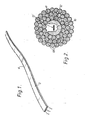
- the preferred undulating optical fibre ribbon structure comprises four optical fibres 1 and two resilient elongate elements 2 of polyethylene terephalate arranged side by side and embedded in an elongate body 3 of silicone acrylate, the four optical fibres being arranged between the two polyethylene terephthalate elements.
- Each of the optical fibres 1 has an overall diameter of 250pm.
- Each of the polyethylene terephthalate elements 2 has a diameter of 200um.
- Each polyethylene terephthalate element 2 is set in such a form that the ribbon structure follows a path of smoothly curved undulations 4 which have radii of curvature of approximately 40mm and whose axes of curvature lie parallel to one another and substantially normal to the longitudinal axis of the optical fibre ribbon structure.
- the undulating optical fibre ribbon structure When the undulating ribbon structure is subjected to a tensile force, the ribbon structure straightens in a lengthwise direction against the action of the undulating polyethylene terephthalate elements 2 thereby reducing the tensile force that would otherwise be applied to the optical fibres 1. After the tensile force is removed, the resilient polyethylene terephthalate elements 2 cause the ribbon structure to return towards its original undulating form.
- the undulating optical fibre ribbon structure has an overall width of 1.6mm and an overall thickness of 0.3mm.
- the overhead flexible electric conductor shown in Figure 2 comprises a central core 11 constituted by a single extruded elongate aluminium alloy member 12 of substantially U-shaped transverse cross-section, the space 16 between the limbs of the U constituting an elongate compartment.
- the central core 11 is surrounded by three layers 15 of helically wound round wires of aluminium-based alloy, the directions of lay of adjacent layers being of opposite hand.
- Loosely housed in the elongate compartment 16 is an undulating optical fibre ribbon structure 17 as shown in Figure 1.
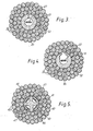
- the overhead flexible electric conductors shown in Figures 3 and 4 are similar in construction to the overhead flexible electric conductor shown in Figure 2 except for the form of the central core and, for convenience, components of the flexible conductors shown in Figures 3 and 4, respectively, that are similar to those of the overhead conductor shown in Figure 2 have been given references greater by ten and by twenty than the references of the corresponding components of the flexible conductor shown in Figure 2.
- the central core 21 is a tube 22 formed by transversely folding a strip of aluminium-based alloy.
- the central core 31 is constituted by a single extruded elongate aluminium alloy member 32 of substantially U-shaped cross-section, the gap between the free ends of the limbs of the U being partially closed to retain the undulating optical fibre ribbon structure 37 in the elongate compartment 36.
- the overhead flexible electric conductor shown in Figure 5 has a central core 41 consisting of two separately formed parts comprising an inner extruded elongate member 42 of aluminium having in its outer surface four circumferentially spaced, longitudinally extending recesses 46 and, surrounding the inner elongate member, a longitudinally applied, transversely folded tape 43 of aluminium, which strip overlies the longitudinally extending recesses to form circumferentially spaced elongate compartments.
- Loosely housed in each of the elongate compartments 46 is an undulating optical fibre ribbon structure 47 as shown in Figure 1.
- the central core 41 is surrounded by three layers 45 of helically wound round wires of aluminium-based alloy, the directions of lay of adjacent layers being of opposite hand.
- the or each elongate compartment may be substantially filled throughout its length with a silicone gel or with a greasy water-impermeable medium.
Landscapes
- Physics & Mathematics (AREA)
- General Physics & Mathematics (AREA)
- Optics & Photonics (AREA)
- Insulated Conductors (AREA)
- Communication Cables (AREA)
- Non-Insulated Conductors (AREA)
- Organic Insulating Materials (AREA)
- Light Guides In General And Applications Therefor (AREA)
- Resistance Heating (AREA)
- Rigid Pipes And Flexible Pipes (AREA)
- Percussion Or Vibration Massage (AREA)
- Suspension Of Electric Lines Or Cables (AREA)
- Forklifts And Lifting Vehicles (AREA)
- Heating, Cooling, Or Curing Plastics Or The Like In General (AREA)
- Chemical Or Physical Treatment Of Fibers (AREA)
- Breeding Of Plants And Reproduction By Means Of Culturing (AREA)
- Materials For Medical Uses (AREA)
Priority Applications (1)
| Application Number | Priority Date | Filing Date | Title |
|---|---|---|---|
| AT84304103T ATE32284T1 (de) | 1983-06-17 | 1984-06-18 | Flexibler elektrischer freileiter. |
Applications Claiming Priority (2)
| Application Number | Priority Date | Filing Date | Title |
|---|---|---|---|
| GB8316494 | 1983-06-17 | ||
| GB838316494A GB8316494D0 (en) | 1983-06-17 | 1983-06-17 | Flexible elongate body |
Publications (3)
| Publication Number | Publication Date |
|---|---|
| EP0129438A2 true EP0129438A2 (de) | 1984-12-27 |
| EP0129438A3 EP0129438A3 (en) | 1986-10-15 |
| EP0129438B1 EP0129438B1 (de) | 1988-01-27 |
Family
ID=10544365
Family Applications (1)
| Application Number | Title | Priority Date | Filing Date |
|---|---|---|---|
| EP84304103A Expired EP0129438B1 (de) | 1983-06-17 | 1984-06-18 | Flexibler elektrischer Freileiter |
Country Status (20)
| Country | Link |
|---|---|
| US (1) | US4632506A (de) |
| EP (1) | EP0129438B1 (de) |
| JP (2) | JPS6017808A (de) |
| KR (1) | KR920000222B1 (de) |
| AT (1) | ATE32284T1 (de) |
| AU (1) | AU567564B2 (de) |
| BR (1) | BR8402972A (de) |
| CA (1) | CA1242602A (de) |
| DE (1) | DE3469094D1 (de) |
| EG (1) | EG17916A (de) |
| ES (1) | ES8606723A1 (de) |
| FI (1) | FI76895C (de) |
| GB (2) | GB8316494D0 (de) |
| HK (1) | HK7187A (de) |
| IN (1) | IN161549B (de) |
| MX (1) | MX161420A (de) |
| NO (1) | NO167607C (de) |
| NZ (1) | NZ208534A (de) |
| ZA (1) | ZA844473B (de) |
| ZW (1) | ZW8984A1 (de) |
Cited By (3)
| Publication number | Priority date | Publication date | Assignee | Title |
|---|---|---|---|---|
| EP0155184A3 (en) * | 1984-03-14 | 1988-08-03 | Bicc Public Limited Company | An improved flexible elongate body |
| WO1992001962A1 (en) * | 1990-07-19 | 1992-02-06 | Nokia Kaapeli Oy | Cable |
| DE19631820C1 (de) * | 1996-08-07 | 1997-07-24 | Felten & Guilleaume Energie | Elektrisches Mehrleiterkabel |
Families Citing this family (31)
| Publication number | Priority date | Publication date | Assignee | Title |
|---|---|---|---|---|
| US4729627A (en) * | 1983-08-15 | 1988-03-08 | Sumitomo Electric Industries, Ltd. | Optical fiber cable for detecting low temperature |
| JPS60112203U (ja) * | 1984-01-05 | 1985-07-30 | 住友電気工業株式会社 | 光伝送用多心フアイバ |
| GB8406635D0 (en) * | 1984-03-14 | 1984-04-18 | Bicc Plc | Optical fibre element |
| GB8423311D0 (en) * | 1984-09-14 | 1984-10-17 | Telephone Cables Ltd | Optical fibre cables |
| JPS61204609A (ja) * | 1985-03-07 | 1986-09-10 | Power Reactor & Nuclear Fuel Dev Corp | イメージファイバ |
| USRE34516E (en) * | 1985-09-14 | 1994-01-18 | Stc Plc | Optical fibre cable |
| EP0216548B1 (de) * | 1985-09-14 | 1995-03-08 | Nortel Networks Corporation | Optisches Kabel |
| US4869573A (en) * | 1986-01-29 | 1989-09-26 | Bicc Public Limited Company | Aerial optical cable and its method of manufacture |
| GB8605016D0 (en) * | 1986-02-28 | 1986-04-09 | Bicc Plc | Optical cable |
| DE3643886A1 (de) * | 1986-03-11 | 1987-09-17 | Kabelmetal Electro Gmbh | Nachrichtenkabel mit lichtwellenleitern |
| JPH0438427Y2 (de) * | 1986-12-29 | 1992-09-09 | ||
| GB2201008B (en) * | 1987-02-12 | 1991-10-23 | Stc Plc | Optical fibre cables |
| US4944570A (en) * | 1987-02-18 | 1990-07-31 | Alcatel Na, Inc. | Fiber optic cable having an extended elongation window |
| JPS63135313U (de) * | 1987-02-27 | 1988-09-06 | ||
| GB2215081B (en) * | 1988-02-11 | 1992-05-20 | Stc Plc | Optical fibre communications cable |
| GB8917347D0 (en) * | 1989-07-28 | 1989-09-13 | Bicc Plc | Overhead electric and optical transmission systems |
| US5202944A (en) * | 1990-06-15 | 1993-04-13 | Westech Geophysical, Inc. | Communication and power cable |
| DE4206652A1 (de) * | 1992-03-03 | 1993-09-09 | Siemens Ag | Optisches kabel und verfahren zu dessen herstellung |
| WO1994028450A1 (en) * | 1993-05-21 | 1994-12-08 | Westech Geophysical, Inc. | Reduced diameter down-hole instrument cable |
| US5339378A (en) * | 1993-10-06 | 1994-08-16 | The United States Of America As Represented By The Secretary Of The Navy | Torque-balanced extendable fiber optic cable |
| US5495546A (en) * | 1994-04-13 | 1996-02-27 | Bottoms, Jr.; Jack | Fiber optic groundwire with coated fiber enclosures |
| US5677974A (en) * | 1995-08-28 | 1997-10-14 | Southern New England Telephone Company | Hybrid communications and power cable and distribution method and network using the same |
| AU3785600A (en) * | 1995-08-28 | 2000-08-10 | Southern New England Telephone Company, The | Hybrid communications and power cable and distribution method and network |
| US5787217A (en) * | 1996-02-15 | 1998-07-28 | Simplex Technologies, Inc. | Fiber optic ground wire cable |
| US5985448A (en) * | 1997-03-03 | 1999-11-16 | Koenig; Erl A. | Open cross-sectional wire |
| US6687437B1 (en) * | 2000-06-05 | 2004-02-03 | Essex Group, Inc. | Hybrid data communications cable |
| US6352374B1 (en) | 2000-06-08 | 2002-03-05 | Amphenol Corporation | Fiber optic connector device |
| US20060140557A1 (en) * | 2001-03-30 | 2006-06-29 | Parris Donald R | Fiber optic cable with strength member formed from a sheet |
| JP2008076427A (ja) * | 2006-09-19 | 2008-04-03 | Tomoegawa Paper Co Ltd | 光ファイバ集合体 |
| JP2013125225A (ja) * | 2011-12-16 | 2013-06-24 | Sumitomo Wiring Syst Ltd | 光ケーブル保護部材およびこれを用いたワイヤハーネス |
| KR20230154920A (ko) * | 2021-03-05 | 2023-11-09 | 씨티씨 글로벌 코포레이션 | 광섬유를 포함하는 오버헤드 전기 케이블 장치 및 강도 부재 조립체 |
Family Cites Families (14)
| Publication number | Priority date | Publication date | Assignee | Title |
|---|---|---|---|---|
| IT988874B (it) * | 1973-06-01 | 1975-04-30 | Pirelli | Mezzo per la trasmissione di segnali nei cavi di telecomuni cazione |
| US4078853A (en) * | 1976-02-25 | 1978-03-14 | Bell Telephone Laboratories, Incorporated | Optical communication cable |
| DK139490B (da) * | 1976-11-09 | 1979-02-26 | Nordiske Kabel Traad | Lysledende element til brug ved optisk transmission. |
| DK138564B (da) * | 1976-11-09 | 1978-09-25 | Nordiske Kabel Traad | Fremgangsmåde ved fremstilling af et lysledende element til anbringelse i et rørformet hylster. |
| GB1598438A (en) * | 1977-05-13 | 1981-09-23 | Bicc Ltd | Overhead electric transmission systems |
| CA1112310A (en) * | 1977-05-13 | 1981-11-10 | Peter Fearns | Overhead electric transmission systems |
| DE2743260C2 (de) * | 1977-09-26 | 1990-05-31 | kabelmetal electro GmbH, 3000 Hannover | Nachrichtenkabel mit Lichtwellenleitern und Verfahren zu seiner Herstellung |
| US4199225A (en) * | 1978-04-07 | 1980-04-22 | Bicc Limited | Optical guides |
| IN157268B (de) * | 1980-10-18 | 1986-02-22 | British Insulated Callenders | |
| FR2509480A1 (fr) * | 1981-07-07 | 1983-01-14 | Lyonnaise Transmiss Optiques | Cable a fibres optiques pouvant supporter de grands allongements |
| JPS5816406A (ja) * | 1981-07-20 | 1983-01-31 | 古河電気工業株式会社 | 光通信線入り架空送電線路用複合撚線 |
| US4372792A (en) * | 1981-10-15 | 1983-02-08 | Bicc Limited | Manufacture of a flexible stranded optical fiber body |
| ZA828667B (en) * | 1981-11-27 | 1983-09-28 | Bicc Plc | A flexible stranded body |
| DE3377299D1 (en) * | 1982-09-23 | 1988-08-11 | Bicc Plc | Method of manufacturing an optical fibre ribbon structure |
-
1983
- 1983-06-17 GB GB838316494A patent/GB8316494D0/en active Pending
-
1984
- 1984-06-12 IN IN477/DEL/84A patent/IN161549B/en unknown
- 1984-06-13 ZA ZA844473A patent/ZA844473B/xx unknown
- 1984-06-14 US US06/620,427 patent/US4632506A/en not_active Expired - Fee Related
- 1984-06-14 CA CA000456585A patent/CA1242602A/en not_active Expired
- 1984-06-15 NZ NZ208534A patent/NZ208534A/en unknown
- 1984-06-15 NO NO842414A patent/NO167607C/no unknown
- 1984-06-15 ZW ZW89/84A patent/ZW8984A1/xx unknown
- 1984-06-15 FI FI842449A patent/FI76895C/fi not_active IP Right Cessation
- 1984-06-15 ES ES533453A patent/ES8606723A1/es not_active Expired
- 1984-06-15 AU AU29415/84A patent/AU567564B2/en not_active Ceased
- 1984-06-15 MX MX201696A patent/MX161420A/es unknown
- 1984-06-17 EG EG368/84A patent/EG17916A/xx active
- 1984-06-18 DE DE8484304103T patent/DE3469094D1/de not_active Expired
- 1984-06-18 JP JP59123899A patent/JPS6017808A/ja active Pending
- 1984-06-18 AT AT84304103T patent/ATE32284T1/de not_active IP Right Cessation
- 1984-06-18 EP EP84304103A patent/EP0129438B1/de not_active Expired
- 1984-06-18 GB GB08415491A patent/GB2141559B/en not_active Expired
- 1984-06-18 BR BR8402972A patent/BR8402972A/pt not_active IP Right Cessation
- 1984-06-19 KR KR1019840003409A patent/KR920000222B1/ko not_active Expired
-
1987
- 1987-01-22 HK HK71/87A patent/HK7187A/xx unknown
-
1990
- 1990-09-11 JP JP1990094829U patent/JPH0346915U/ja active Pending
Cited By (4)
| Publication number | Priority date | Publication date | Assignee | Title |
|---|---|---|---|---|
| EP0155184A3 (en) * | 1984-03-14 | 1988-08-03 | Bicc Public Limited Company | An improved flexible elongate body |
| WO1992001962A1 (en) * | 1990-07-19 | 1992-02-06 | Nokia Kaapeli Oy | Cable |
| AU649701B2 (en) * | 1990-07-19 | 1994-06-02 | Nokia Kaapeli Oy | Cable |
| DE19631820C1 (de) * | 1996-08-07 | 1997-07-24 | Felten & Guilleaume Energie | Elektrisches Mehrleiterkabel |
Also Published As
| Publication number | Publication date |
|---|---|
| NO167607C (no) | 1991-11-20 |
| ES533453A0 (es) | 1986-04-16 |
| EP0129438B1 (de) | 1988-01-27 |
| JPH0346915U (de) | 1991-04-30 |
| JPS6017808A (ja) | 1985-01-29 |
| FI76895C (fi) | 1988-12-12 |
| FI76895B (fi) | 1988-08-31 |
| US4632506A (en) | 1986-12-30 |
| GB8415491D0 (en) | 1984-07-25 |
| GB8316494D0 (en) | 1983-07-20 |
| AU567564B2 (en) | 1987-11-26 |
| FI842449A7 (fi) | 1984-12-18 |
| HK7187A (en) | 1987-01-28 |
| AU2941584A (en) | 1984-12-20 |
| KR850000737A (ko) | 1985-03-09 |
| BR8402972A (pt) | 1985-05-28 |
| ATE32284T1 (de) | 1988-02-15 |
| EG17916A (en) | 1991-06-30 |
| DE3469094D1 (en) | 1988-03-03 |
| ZA844473B (en) | 1985-02-27 |
| CA1242602A (en) | 1988-10-04 |
| ES8606723A1 (es) | 1986-04-16 |
| KR920000222B1 (ko) | 1992-01-10 |
| GB2141559B (en) | 1986-04-09 |
| ZW8984A1 (en) | 1984-10-03 |
| FI842449A0 (fi) | 1984-06-15 |
| GB2141559A (en) | 1984-12-19 |
| EP0129438A3 (en) | 1986-10-15 |
| NO842414L (no) | 1984-12-18 |
| IN161549B (de) | 1987-12-19 |
| NO167607B (no) | 1991-08-12 |
| MX161420A (es) | 1990-09-24 |
| NZ208534A (en) | 1987-07-31 |
Similar Documents
| Publication | Publication Date | Title |
|---|---|---|
| US4632506A (en) | Overhead flexible electric conductor | |
| EP0155184A2 (de) | Biegsamer langgezogener Körper | |
| US4491387A (en) | Overhead electric and optical transmission systems | |
| US4723832A (en) | Composite overhead cable structure for electric and optical transmission | |
| EP0554789A1 (de) | Optisches Kabel | |
| GB1598438A (en) | Overhead electric transmission systems | |
| EP0157516B1 (de) | Fiberoptisches Bauteil | |
| EP0814355A1 (de) | Leichtes Lichtwellenleiter-Erdseil | |
| EP0200104B1 (de) | Heterogenes Freiluftstarkstromkabel | |
| EP0099745A1 (de) | Flexibler langgestreckter Körper | |
| EP0092980A2 (de) | Flexibler gestreckter Körper | |
| EP0116754A1 (de) | Elektrisches Hochspannungsenergiekabel mit Anpassung an thermische Ausdehnung | |
| JPH11203955A (ja) | 光複合架空地線 | |
| GB2183060A (en) | Optical fibre cable |
Legal Events
| Date | Code | Title | Description |
|---|---|---|---|
| PUAI | Public reference made under article 153(3) epc to a published international application that has entered the european phase |
Free format text: ORIGINAL CODE: 0009012 |
|
| AK | Designated contracting states |
Designated state(s): AT BE DE FR GB IT NL SE |
|
| 17P | Request for examination filed |
Effective date: 19850122 |
|
| PUAL | Search report despatched |
Free format text: ORIGINAL CODE: 0009013 |
|
| AK | Designated contracting states |
Kind code of ref document: A3 Designated state(s): AT BE DE FR GB IT NL SE |
|
| 17Q | First examination report despatched |
Effective date: 19870126 |
|
| RBV | Designated contracting states (corrected) |
Designated state(s): AT BE DE FR IT NL SE |
|
| GRAA | (expected) grant |
Free format text: ORIGINAL CODE: 0009210 |
|
| AK | Designated contracting states |
Kind code of ref document: B1 Designated state(s): AT BE DE FR IT NL SE |
|
| REF | Corresponds to: |
Ref document number: 32284 Country of ref document: AT Date of ref document: 19880215 Kind code of ref document: T |
|
| REF | Corresponds to: |
Ref document number: 3469094 Country of ref document: DE Date of ref document: 19880303 |
|
| ET | Fr: translation filed | ||
| ITF | It: translation for a ep patent filed | ||
| PLBE | No opposition filed within time limit |
Free format text: ORIGINAL CODE: 0009261 |
|
| STAA | Information on the status of an ep patent application or granted ep patent |
Free format text: STATUS: NO OPPOSITION FILED WITHIN TIME LIMIT |
|
| 26N | No opposition filed | ||
| PGFP | Annual fee paid to national office [announced via postgrant information from national office to epo] |
Ref country code: FR Payment date: 19930512 Year of fee payment: 10 |
|
| PGFP | Annual fee paid to national office [announced via postgrant information from national office to epo] |
Ref country code: AT Payment date: 19930513 Year of fee payment: 10 |
|
| PGFP | Annual fee paid to national office [announced via postgrant information from national office to epo] |
Ref country code: SE Payment date: 19930518 Year of fee payment: 10 |
|
| PGFP | Annual fee paid to national office [announced via postgrant information from national office to epo] |
Ref country code: DE Payment date: 19930524 Year of fee payment: 10 |
|
| PGFP | Annual fee paid to national office [announced via postgrant information from national office to epo] |
Ref country code: BE Payment date: 19930527 Year of fee payment: 10 |
|
| ITTA | It: last paid annual fee | ||
| PGFP | Annual fee paid to national office [announced via postgrant information from national office to epo] |
Ref country code: NL Payment date: 19930630 Year of fee payment: 10 |
|
| PG25 | Lapsed in a contracting state [announced via postgrant information from national office to epo] |
Ref country code: AT Effective date: 19940618 |
|
| PG25 | Lapsed in a contracting state [announced via postgrant information from national office to epo] |
Ref country code: SE Effective date: 19940619 |
|
| PG25 | Lapsed in a contracting state [announced via postgrant information from national office to epo] |
Ref country code: BE Effective date: 19940630 |
|
| BERE | Be: lapsed |
Owner name: BICC P.L.C. Effective date: 19940630 |
|
| PG25 | Lapsed in a contracting state [announced via postgrant information from national office to epo] |
Ref country code: NL Effective date: 19950101 |
|
| EUG | Se: european patent has lapsed |
Ref document number: 84304103.9 Effective date: 19950110 |
|
| NLV4 | Nl: lapsed or anulled due to non-payment of the annual fee | ||
| PG25 | Lapsed in a contracting state [announced via postgrant information from national office to epo] |
Ref country code: FR Effective date: 19950228 |
|
| PG25 | Lapsed in a contracting state [announced via postgrant information from national office to epo] |
Ref country code: DE Effective date: 19950301 |
|
| EUG | Se: european patent has lapsed |
Ref document number: 84304103.9 |
|
| REG | Reference to a national code |
Ref country code: FR Ref legal event code: ST |