EP0129446A2 - Automatischer Farbenanalysator, mit Verwendung der minimal/maximalen Videosignalhöhen - Google Patents
Automatischer Farbenanalysator, mit Verwendung der minimal/maximalen Videosignalhöhen Download PDFInfo
- Publication number
- EP0129446A2 EP0129446A2 EP84304179A EP84304179A EP0129446A2 EP 0129446 A2 EP0129446 A2 EP 0129446A2 EP 84304179 A EP84304179 A EP 84304179A EP 84304179 A EP84304179 A EP 84304179A EP 0129446 A2 EP0129446 A2 EP 0129446A2
- Authority
- EP
- European Patent Office
- Prior art keywords
- circuit
- peak
- color
- video
- video signals
- Prior art date
- Legal status (The legal status is an assumption and is not a legal conclusion. Google has not performed a legal analysis and makes no representation as to the accuracy of the status listed.)
- Withdrawn
Links
- 238000012935 Averaging Methods 0.000 claims description 10
- 238000000034 method Methods 0.000 claims description 8
- 230000000052 comparative effect Effects 0.000 claims description 7
- 239000003086 colorant Substances 0.000 claims description 4
- 230000001360 synchronised effect Effects 0.000 claims description 4
- 230000001419 dependent effect Effects 0.000 claims 4
- 238000012937 correction Methods 0.000 description 24
- 239000000463 material Substances 0.000 description 10
- 230000005540 biological transmission Effects 0.000 description 3
- 230000000295 complement effect Effects 0.000 description 3
- 238000010586 diagram Methods 0.000 description 3
- PENWAFASUFITRC-UHFFFAOYSA-N 2-(4-chlorophenyl)imidazo[2,1-a]isoquinoline Chemical compound C1=CC(Cl)=CC=C1C1=CN(C=CC=2C3=CC=CC=2)C3=N1 PENWAFASUFITRC-UHFFFAOYSA-N 0.000 description 2
- 238000013459 approach Methods 0.000 description 2
- 230000007935 neutral effect Effects 0.000 description 2
- 238000004886 process control Methods 0.000 description 2
- 230000002238 attenuated effect Effects 0.000 description 1
- 238000011161 development Methods 0.000 description 1
- 230000000694 effects Effects 0.000 description 1
- 230000002708 enhancing effect Effects 0.000 description 1
- 238000011156 evaluation Methods 0.000 description 1
- 238000004519 manufacturing process Methods 0.000 description 1
- 238000005259 measurement Methods 0.000 description 1
- 238000012545 processing Methods 0.000 description 1
Images


Classifications
-
- H—ELECTRICITY
- H04—ELECTRIC COMMUNICATION TECHNIQUE
- H04N—PICTORIAL COMMUNICATION, e.g. TELEVISION
- H04N1/00—Scanning, transmission or reproduction of documents or the like, e.g. facsimile transmission; Details thereof
- H04N1/46—Colour picture communication systems
- H04N1/56—Processing of colour picture signals
- H04N1/60—Colour correction or control
- H04N1/6027—Correction or control of colour gradation or colour contrast
-
- H—ELECTRICITY
- H04—ELECTRIC COMMUNICATION TECHNIQUE
- H04N—PICTORIAL COMMUNICATION, e.g. TELEVISION
- H04N1/00—Scanning, transmission or reproduction of documents or the like, e.g. facsimile transmission; Details thereof
- H04N1/46—Colour picture communication systems
- H04N1/56—Processing of colour picture signals
- H04N1/60—Colour correction or control
- H04N1/6011—Colour correction or control with simulation on a subsidiary picture reproducer
Definitions
- the invention relates generally to automatic color analysis and, in particular, a color analyzer for automatically providing color analysis based on the minimum and/or maximum video level.
- the invention is an apparatus including a color analyzer for analyzing films such as positives and negatives having a plurality of adjustable control elements for acting on color representative video signals derived from the film.
- the analyzer varies a video signal characteristic and thereby varies the generated display of the video signal.
- the apparatus according to the invention comprises first means for detecting the video level of the color representative video signals, second means for comparing the detected video level to a predetermined amplitude, and third means responsive to the second means for adjusting the control elements.
- the apparatus according to the invention includes analyzers as disclosed in U.S. Patent Nos. 2,976,348; 2,977,407; 3,123,666; 3,128,333; 3,131,252; 3,800,071; 3,800,075.
- the apparatus according to the invention may be used in combination with scanners as disclosed in U.S. Patent No. 3,002,048 and process control apparatus as disclosed in U.S. Patent No. 4,300,158.
- an analyzer refers to a device used in the photofinishing industry to predict the exposure values of various negative and positive material (herein referred to as films).
- films various negative and positive material
- an automatic device which predicts exposure values is a necessity.
- Such a device is currently used in the amateur photofinishing industry and is useful for lower grades of professional photographic work.
- automatic analysis provides a preliminary evaluation in comparison which aids the operator in analyzing the film and saves operator time.
- the apparatus according to the invention includes a color analyzer generally referred to by reference character 100.
- color analyzer refer to electronic apparatus for use in the processing of photographic color film to predict the exposure requirements for producing print materials, i.e. print film or photographic paper, and especially to apparatus of the type for evaluating the exposure and color balance of negative color film in order to obtain an indication of how the printing of the positive color film should be handled in order to obtain suitable color positives from the color negative.
- the apparatus according to the invention includes an electronic previewer for simulating an image produced by photofinishing such as disclosed in U.S. Patent No. 2,976,348, incorporated herein by reference.
- Such analyzers evaluate negative color film and obtain the necessary process control information for the printing of the positive color film or photographic prints.
- Analyzer 100 includes a scanner 101 or other electro-optic system which optically detects the colors in the film 50 being analyzed and provides a video signal via line 102 corresponding to the color content of the print material, i.e. the print film or photographic paper, which is simulated by the analyzer.
- the video signal is then processed by printing simulator circuits 103 which include operator controls simulating the exposure of film 50.
- the particular settings of printing simulator 103 circuits selected by the operator are displayed on display 104 and the video signal acted on by printing simulator circuits 103 is provided via line 106 to color computer 107 including photofinishing simulator circuits.
- Color computer 107 simulates the photochemical printing development process and provides a video output signal to tricolor display 108.
- the operator of analyzer 100 views display 108 resulting from film 50 and adjusts the controls of printing simulator 103 until the operator is satisfied with display 108. The operator then reads the control settings from display 104 and uses these settings in the process of developing a positive or print of film 50.
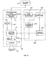
- correction circuit 500 includes peak detectors 200, A/D converters 300 and digital computer 400. As illustrated in figure 1, correction circuit 500 is contemplated for use in combination with color film analyzer 100 for analyzing negative film 50. However, correction circuit 500 may be used in combination with any type of film analyzer.
- Analyzer 100 includes an electro-optic system 110 which scans the film to be analyzed.
- Electro-optic system 110 scans the film and generates a video signal via line 111 which represents the graphic information (i.e. color content) in the film.
- system 110 develops vertical synchronization (sync) and horizontal sync pulses during the raster scan of the film.
- the video signal representing the color content of the film being analyzed is acted on by active attenuators 112 which are responsive to operator controls.
- Active attenuators 112 essentially simulate the printing process and permit the operator to determine the best exposure values to be used when the film being analyzed is printed.
- the attenuated video signal is then provided via line 113 to exponential amplifiers 114 and then to tricolor display 108 for viewing by the operator. As a result, the operator can view the changes resulting from the operator's manipulation of the controls of attenuators 112.
- the video signal as provided to exponential amplifiers 114 has three voltage components representing the three basic color components of the print material, i.e. the positive print film or the photographic paper.
- D represents the yellow, magenta and cyan density in the print material.
- Detectors 200 are yellow, magenta and cyan peak detectors 201 which detect the peak of each color corresponding to each component of the video signal.
- the detected peaks of each field are provided via line 202 to A/D converter 300 which is an eight-bit analog-to-digital converter.
- microcomputer 401 is provided with three eight-bit words from which the peak black level of the film being analyzed can be determined.
- the peak black level is the peak of the levels of the three basic color components.
- the invention has been specifically described with regard to automatic color correction based on the peak black level of the video signals which in this case are derived from negative input materials.
- any minimum or maximum, or combination thereof, of the video signal level may be detected and used to achieve automatic color correction in accordance with the invention.
- minimum video signal levels or average peak levels or a weighted combination thereof may be employed to generate automatic color correction.
- the individual yellow, magenta and cyan video signals which are provided to detectors 200 result in the measurement of the peak video amplitude in each channel independently.
- the DC voltage which is produced by detectors 201 represents the density of the maximum cyan, magenta or yellow signal in the print material.
- This DC voltage is provided to microcomputer 401 for comparison to a reference code stored therein.
- the reference codes and the eight-bit words corresponding to the uncorrected film are compared by microcomputer 401.
- Microcomputer 401 uses the comparative difference to generate a correction signal according to an algorithm such as a standard linear comparison.
- the correction signals are provided via line 403 to binary data register 115 which in turn provides the information in pulse form via line 116 to active attenuators 112. All correction signals are also provided via line 117 through BCD data register 118 and via line 119 to exposure data display 104.
- the operator selects the mode of operation of the automatic analysis system by manipulating the controls 402 associated with microcomputer 401.
- These controls may include function keys or a standard keyboard permitting entry of commands and other data.
- the reference data stored in register 118 may be entered via microcomputer 401 based on previous experience or may be generated by analyzing a reference film. If reference data is to be generated, controls 402 are set to the reference mode, the reference film is placed in the film gate of analyzer 100 and microcomputer 401 then analyzes the reference film and stores the resulting reference data i.e., the peak levels derived from the reference film.
- area gate generator 203 may be selectively activated to control which of the video signals are detected by detectors 201.
- vertical and horizontal sync pulses generated by electro-optic system 110 are provided via line 120 to area gate generator 203.
- Area gate generator 203 is synchronized to the vertical and horizontal sync pulses.
- Generator 203 provides signals derived from adjustable delay multivibrators used to form a gate (window) which selectively turns peak detectors 201 on or off via control line 204.
- the area to be detected within a given field is defined by the operator by providing area gate generator 203 with a count of the vertical and horizontal sync pulses which occur during the scanning of the limited area.
- FIG. 3 illustrates an automatic correcting printer according to the invention.
- a color video camera 700 scans film 50 and provides the video signals to peak sample and hold circuits 701. Peak sample and hold circuits 701 retain the particular minimum or maximum video level which is being used for color correction and provides such to comparator 702 which compares the peaks to a reference held in storage 703. The compared information is then provided to power supply 704 of printer 705 and used to control the output of light source 706 which exposes the film.
- the system described in Figures 1-3 may provide incomplete results when analyzing underexposed or overexposed films such as negatives. These results will be manifested in overall density errors or discrepancies in the analysis. With the system of Figures 1-3, underexposed films may be analyzed so that the resulting images are too dark and overexposed films may be analyzed so that the resulting images are too light. Such results can be caused by the distortions in the dynamic range of the underexposed and overexposed negatives when such negatives are printed on the very commonly used photographic papers.
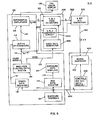
- Figures 4-6 illustrate a system which corrects such distortions and allows underexposed and overexposed films such as negatives to be automatically analyzed for proper printing densities.
- the system of Figures 4-6 uses underexposed and overexposed reference negatives in addition to the normal reference negative to establish corrections to the original automatic system. These corrections are stored in microcomputer 401 and are calculated by an algorithm for each film being analyzed based on the amount that the film which is being analyzed is overexposed or underexposed as compared to the normal negative.
- the amount of underexposure or overexposure is determined by averaging circuit 206.
- the exposure level of the film being analyzed is evaluated by yellow, magenta and cyan averaging circuits which measure the average level of the video before attenuator controls 112.
- the average value is lower than the normal film and for underexposed films the average value of the light through the film is greater than the normal reference film.
- a weighted average of the average of the yellow, magenta and cyan transmissions is calculated by microcomputer 401 according to the algorithm resident therein.
- a set of films consisting of one normally exposed film and multiple overexposed and underexposed films of the same subject are correctly analyzed in the reference mode.
- the values read by the yellow, magenta and cyan averaging circuits 206 and the yellow, magenta and cyan peak detectors 200 are stored in microcomputer 401. Subsequently, when an unkown film is analyzed in the automatic mode, the average transmission through the film is calculated and compared to the average transmission of the various reference films and the most appropriate reference film values are selected.
- microcomputer 401 may be provided with an algorithm which interpolates between the various reference films to select the most appropriate reference value.
- the yellow, magenta and cyan peak detected color values for the selected reference are then provided via line 403 to satisfy the feedback loop for the color of the unkown film being analyzed.
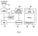
- Figure 6 illustrates an automatic correcting printer according to the invention including averaging circuit 707 for evaluating densities.
- Color video camera 700 scans film 50 and provides the video signals to peak sample and hold circuits 701 and to averaging circuits 707.
- Peak sample and hold circuit 701 retain the particular minimum or maximum video level which is being used for color correction and provides such to comparator 702.
- the averaged video information is provided to microcomputer 708 which selects or computes a reference from reference storage 703.
- Comparator 702 compares the peaks of the selected reference to the video levels held by sample and hold circuit 701. The compared information is then provided to power supply 704 of printer 705 and used to control the output of light source 706 which exposes the film.
- controls 402 are set to the reference mode and electro-optic system 110 scans the reference film or films.
- the individual yellow, magenta and cyan video signals derived from the reference film or films are peak detected by detectors 201 and averaged by averaging circuit 206.
- the detected peaks are converted to eight-bit digital words by converter 300 and stored in microcomputer 401.
- Controls 402 are then set for the automatic or manual mode.
- the automatic mode the negative to be analyzed is scanned by electro-optic system 110.
- the individual yellow, magenta and cyan video signals corresponding to the film are peak detected by detectors 201 and averaged by averager 206.
- the detected peaks and average are converted to eight-bit digital words by converter 300 and provided to microcomputer 401.
- Microcomputer 401 selects a reference and compares the eight-bit digital words representing the peaks of the selected reference data to the peaks of the film being analyzed. For example, assume that each yellow, magenta or cyan video signal may be in the voltage range between -5 volts and +5 volts.
- microcomputer 401 would compare these peaks and upon determining a voltage difference of minus -2 volts would provide data via line 403 to binary data register 115 indicating the correction necessary. This correction may be based on an algorithm stored in microcomputer 401 or may be a linearly related command instructing active attenuators to decrease the voltage of the blue video signal (blue being the complement of yellow) by 2 volts.
- microcomputer 401 would compare this to the selected reference magenta level stored therein, determine their equivalence and indicate that no correction is necessary in the green video signal (green being the complement of magenta). Assuming that the film being analyzed has a peak cyan level of +3 volts, microcomputer 401 would provide a correction signal to register 115 based on the difference of +2 volts to correct the red signal (red being the complement of cyan).
- Controls 402 may then be set to the manual mode so that the operator may adjust active attenuator 112 directly by adjusting exposure controls 1 2 1.
- exposure data display 104 Upon completion of the automatic and optional manual analysis, exposure data display 104 indicates the correction information to be used during the actual printing of the film which was analyzed. Since corrections are stored in both binary data register 115 and BCD data register 118, display 104 indicates the final correction information.
- the area on the film being considered for generating the peak black level may be limited by providing input information to area gate generator 2 0 3 .
- the gate generator 203 provides pulses which correspond in time to the raster of the limited area.
- generator 203 turns detectors 201 on only during that portion of the raster scan which lies within the defined area.
Landscapes
- Engineering & Computer Science (AREA)
- Multimedia (AREA)
- Signal Processing (AREA)
- Control Of Exposure In Printing And Copying (AREA)
- Color Television Image Signal Generators (AREA)
Applications Claiming Priority (4)
| Application Number | Priority Date | Filing Date | Title |
|---|---|---|---|
| US50618183A | 1983-06-21 | 1983-06-21 | |
| US506181 | 1983-06-21 | ||
| US58419684A | 1984-02-27 | 1984-02-27 | |
| US584196 | 1990-09-18 |
Publications (2)
| Publication Number | Publication Date |
|---|---|
| EP0129446A2 true EP0129446A2 (de) | 1984-12-27 |
| EP0129446A3 EP0129446A3 (de) | 1986-05-28 |
Family
ID=27055390
Family Applications (1)
| Application Number | Title | Priority Date | Filing Date |
|---|---|---|---|
| EP84304179A Withdrawn EP0129446A3 (de) | 1983-06-21 | 1984-06-20 | Automatischer Farbenanalysator, mit Verwendung der minimal/maximalen Videosignalhöhen |
Country Status (3)
| Country | Link |
|---|---|
| EP (1) | EP0129446A3 (de) |
| AU (1) | AU2932384A (de) |
| CA (1) | CA1230291A (de) |
Cited By (7)
| Publication number | Priority date | Publication date | Assignee | Title |
|---|---|---|---|---|
| EP0209266A1 (de) * | 1985-06-27 | 1987-01-21 | Crosfield Electronics Limited | Farbdatensichtgeräte |
| DE3526133A1 (de) * | 1985-07-22 | 1987-01-29 | Hell Rudolf Dr Ing Gmbh | Verfahren zur herstellung von farbbildern |
| DE3729188A1 (de) * | 1986-09-01 | 1988-03-03 | Fuji Photo Film Co Ltd | Verschiebedriftkorrektur fuer ein farbfilminspektionsgeraet |
| EP0267805A3 (en) * | 1986-11-14 | 1989-10-25 | Canon Kabushiki Kaisha | Image reading apparatus |
| EP0356328A3 (de) * | 1988-08-23 | 1991-10-16 | YAMATOYA & CO., LTD. | Tonumwandlungsverfahren für Bilder |
| EP0933679A3 (de) * | 1998-01-30 | 1999-12-08 | Eastman Kodak Company | Photographisches Behandlungsgerät und Verfahren |
| WO2000004492A3 (en) * | 1998-07-15 | 2001-10-25 | Imation Corp | Imaging system and method |
Families Citing this family (2)
| Publication number | Priority date | Publication date | Assignee | Title |
|---|---|---|---|---|
| US4755870A (en) * | 1983-07-11 | 1988-07-05 | Colorization Inc. | Coloring a black and white signal using motion detection |
| US4694330A (en) * | 1984-08-21 | 1987-09-15 | Sony Corporation | Color correction circuit |
Family Cites Families (7)
| Publication number | Priority date | Publication date | Assignee | Title |
|---|---|---|---|---|
| US4097892A (en) * | 1976-10-08 | 1978-06-27 | Balding George H | Video color film analyzer |
| US4194838A (en) * | 1977-02-22 | 1980-03-25 | Bey Michael P | Digital color densitometer and exposure meter |
| US4300158A (en) * | 1977-07-18 | 1981-11-10 | Hazeltine Corporation | Process control apparatus |
| DE2848376C2 (de) * | 1978-11-08 | 1983-12-15 | Dr.-Ing. Rudolf Hell Gmbh, 2300 Kiel | Einrichtung zur Nachkorrektur von Standardfarbkorrekturen bei der Farbbildaufzeichnung |
| DE2853509C2 (de) * | 1978-12-12 | 1983-02-03 | Dr.-Ing. Rudolf Hell Gmbh, 2300 Kiel | Einrichtung zur Herstellung von Farbauszügen |
| US4340905A (en) * | 1980-09-12 | 1982-07-20 | Balding George H | Photographic printer and color film analyzer apparatus |
| CH651403A5 (de) * | 1980-12-19 | 1985-09-13 | Walter Dr Grossmann | Verfahren und vorrichtung zum belichten von aufzeichnungsmaterial bei der herstellung photographischer farbkopien. |
-
1984
- 1984-06-13 AU AU29323/84A patent/AU2932384A/en not_active Abandoned
- 1984-06-18 CA CA000456781A patent/CA1230291A/en not_active Expired
- 1984-06-20 EP EP84304179A patent/EP0129446A3/de not_active Withdrawn
Cited By (13)
| Publication number | Priority date | Publication date | Assignee | Title |
|---|---|---|---|---|
| EP0209266A1 (de) * | 1985-06-27 | 1987-01-21 | Crosfield Electronics Limited | Farbdatensichtgeräte |
| US4843379A (en) * | 1985-06-27 | 1989-06-27 | Crosfield Electronics (Usa) Limited | Color displays |
| DE3526133A1 (de) * | 1985-07-22 | 1987-01-29 | Hell Rudolf Dr Ing Gmbh | Verfahren zur herstellung von farbbildern |
| DE3729188A1 (de) * | 1986-09-01 | 1988-03-03 | Fuji Photo Film Co Ltd | Verschiebedriftkorrektur fuer ein farbfilminspektionsgeraet |
| US4969053A (en) * | 1986-11-14 | 1990-11-06 | Canon Kabushiki Kaisha | A color film reading apparatus providing high-gradation color signals |
| US4922335A (en) * | 1986-11-14 | 1990-05-01 | Canon Kabushiki Kaisha | Color film reading apparatus providing high-gradation color signals |
| EP0267805A3 (en) * | 1986-11-14 | 1989-10-25 | Canon Kabushiki Kaisha | Image reading apparatus |
| EP0578336A1 (de) * | 1986-11-14 | 1994-01-12 | Canon Kabushiki Kaisha | Bildlesevorrichtung |
| EP0356328A3 (de) * | 1988-08-23 | 1991-10-16 | YAMATOYA & CO., LTD. | Tonumwandlungsverfahren für Bilder |
| EP0933679A3 (de) * | 1998-01-30 | 1999-12-08 | Eastman Kodak Company | Photographisches Behandlungsgerät und Verfahren |
| US6101000A (en) * | 1998-01-30 | 2000-08-08 | Eastman Kodak Company | Photographic processing apparatus and method |
| WO2000004492A3 (en) * | 1998-07-15 | 2001-10-25 | Imation Corp | Imaging system and method |
| US6462835B1 (en) | 1998-07-15 | 2002-10-08 | Kodak Polychrome Graphics, Llc | Imaging system and method |
Also Published As
| Publication number | Publication date |
|---|---|
| EP0129446A3 (de) | 1986-05-28 |
| AU2932384A (en) | 1985-01-03 |
| CA1230291A (en) | 1987-12-15 |
Similar Documents
| Publication | Publication Date | Title |
|---|---|---|
| US4168120A (en) | Automatic exposure corrections for photographic printer | |
| EP0221133B1 (de) | Verfahren zum auffinden und kopieren von mit schmalbandigem licht belichteten farbfotos | |
| US4792847A (en) | Method for automatically setting signal processing conditions in image input/output system | |
| EP0221113B1 (de) | Digitale belichtungsregelung für photographische bilder | |
| US4120581A (en) | Apparatus for automatically printing color photographs | |
| US4217648A (en) | Method and apparatus for evaluating color photographic negatives prior to copying | |
| EP0255128A2 (de) | Automatisches photographisches Kopiergerät mit Simulator und Verfahren zum Eichen des Simulators dieses Kopiergerätes | |
| US4642683A (en) | Digital image processing method for images with bimodal tone value distribution | |
| US4279505A (en) | Method for print exposure control | |
| US4168121A (en) | Automatic snow/beach correction for photographic printer | |
| US5019858A (en) | Photographic printer | |
| CA1230291A (en) | Automatic color analysis based on minimum/maximum video level | |
| CA1177411A (en) | Exposure and contrast determination by prescanning in electronic photoprinting systems | |
| JPH084318B2 (ja) | カラ−原画の複製方法及び装置 | |
| EP0221139B1 (de) | Verfahren zum auffinden von unbelichteten bildern in einem photographischen farbkopiergerät | |
| US4710019A (en) | Photographic printer and method for determining exposure amount thereof | |
| US5699451A (en) | Correction of color defects during printing of photographs | |
| US4149799A (en) | Photographic printer with automatic slope compensation | |
| US6373993B1 (en) | Image processing method and image processing apparatus | |
| EP0376146B1 (de) | Verfahren zum Einstellen der Belichtungsbedingungen in einem photographischen Printer | |
| EP0428790B1 (de) | Bildreproduktionsverfahren | |
| JP2837757B2 (ja) | 写真焼付装置のプリント方法 | |
| JPS60216348A (ja) | 最小/最大画像レベルに基づく自動カラ−分析器 | |
| US6901219B2 (en) | Method and device for automatically calibrating a digitizer | |
| SU898376A1 (ru) | Электронно-копировальный прибор |
Legal Events
| Date | Code | Title | Description |
|---|---|---|---|
| PUAI | Public reference made under article 153(3) epc to a published international application that has entered the european phase |
Free format text: ORIGINAL CODE: 0009012 |
|
| AK | Designated contracting states |
Designated state(s): CH DE FR GB IT LI |
|
| PUAL | Search report despatched |
Free format text: ORIGINAL CODE: 0009013 |
|
| RHK1 | Main classification (correction) |
Ipc: G03B 27/73 |
|
| AK | Designated contracting states |
Kind code of ref document: A3 Designated state(s): CH DE FR GB IT LI |
|
| STAA | Information on the status of an ep patent application or granted ep patent |
Free format text: STATUS: THE APPLICATION IS DEEMED TO BE WITHDRAWN |
|
| 18D | Application deemed to be withdrawn |
Effective date: 19870128 |
|
| RIN1 | Information on inventor provided before grant (corrected) |
Inventor name: EISENHUTH, ARTHUR J. |