EP0129456A2 - Verfahren und Vorrichtung zur Zentrierung einer optischen Faser relativ zu einer Linse in einem Stecker und so erhaltenes Verbindungselement - Google Patents
Verfahren und Vorrichtung zur Zentrierung einer optischen Faser relativ zu einer Linse in einem Stecker und so erhaltenes Verbindungselement Download PDFInfo
- Publication number
- EP0129456A2 EP0129456A2 EP84401055A EP84401055A EP0129456A2 EP 0129456 A2 EP0129456 A2 EP 0129456A2 EP 84401055 A EP84401055 A EP 84401055A EP 84401055 A EP84401055 A EP 84401055A EP 0129456 A2 EP0129456 A2 EP 0129456A2
- Authority
- EP
- European Patent Office
- Prior art keywords
- lens
- ring
- fiber
- end piece
- axis
- Prior art date
- Legal status (The legal status is an assumption and is not a legal conclusion. Google has not performed a legal analysis and makes no representation as to the accuracy of the status listed.)
- Withdrawn
Links
Images


Classifications
-
- G—PHYSICS
- G02—OPTICS
- G02B—OPTICAL ELEMENTS, SYSTEMS OR APPARATUS
- G02B6/00—Light guides; Structural details of arrangements comprising light guides and other optical elements, e.g. couplings
- G02B6/24—Coupling light guides
- G02B6/36—Mechanical coupling means
- G02B6/38—Mechanical coupling means having fibre to fibre mating means
- G02B6/3807—Dismountable connectors, i.e. comprising plugs
- G02B6/3833—Details of mounting fibres in ferrules; Assembly methods; Manufacture
- G02B6/3855—Details of mounting fibres in ferrules; Assembly methods; Manufacture characterised by the method of anchoring or fixing the fibre within the ferrule
- G02B6/3861—Adhesive bonding
-
- G—PHYSICS
- G02—OPTICS
- G02B—OPTICAL ELEMENTS, SYSTEMS OR APPARATUS
- G02B6/00—Light guides; Structural details of arrangements comprising light guides and other optical elements, e.g. couplings
- G02B6/24—Coupling light guides
- G02B6/26—Optical coupling means
- G02B6/32—Optical coupling means having lens focusing means positioned between opposed fibre ends
-
- G—PHYSICS
- G02—OPTICS
- G02B—OPTICAL ELEMENTS, SYSTEMS OR APPARATUS
- G02B6/00—Light guides; Structural details of arrangements comprising light guides and other optical elements, e.g. couplings
- G02B6/24—Coupling light guides
- G02B6/36—Mechanical coupling means
- G02B6/38—Mechanical coupling means having fibre to fibre mating means
- G02B6/3807—Dismountable connectors, i.e. comprising plugs
- G02B6/3833—Details of mounting fibres in ferrules; Assembly methods; Manufacture
- G02B6/3834—Means for centering or aligning the light guide within the ferrule
- G02B6/3835—Means for centering or aligning the light guide within the ferrule using discs, bushings or the like
Definitions
- the present invention relates to a device for centering an optical fiber and a lens in a tip, as well as a connector element thus obtained.
- the invention relates to a method and a device for relative centering of an optical fiber and a lens, allowing the precise mounting of a lens on a tip of the aforementioned type, and ensuring precisely the alignment between the axis of the fiber and the axis of the lens.
- the method of relative centering of a lens and of a tip comprises the steps consisting in installing a tip not equipped with an optical fiber, to be positioned at the downstream end of the tip a centering device, to introduce an optical fiber through the end piece and the centering device so that the fiber is kept centered by the centering device, to introduce glue into the tip to fix the fiber in position, to move the centering away, to cleave the fiber once the glue has solidified, to introduce the downstream end of the tip in a ring, to introduce the lens in the ring while leaving a portion of the lens protruding therefrom sufficient for it to be able to be taken between the jaws of a micro-manipulator, to position the lens with the micro-manipulator so that the end of the optical fiber either centered at the focal point of the lens and the axis of the optical fiber aligned with the optical axis of the lens, the positioning control being ensured by a measuring device capable of receiving light emitted by the optical fiber and arranged so
- the tip and the centering device can be positioned along the same reference axis with respect to which the alignment of the optical fiber and the lens is carried out.
- the V-shaped profile groove is advantageously in two aligned parts, respectively upstream and downstream, and separated by a housing receiving the micro-manipulator and the reference part is then placed in the downstream part.
- the device is characterized in that it comprises a plate having a frustoconical longitudinal bore whose axis is the reference axis, in that said first holding means is a first clamp having jaws whose outer surface cooperates with the frustoconical bore to maintain the cylindrical endpiece in position along the reference axis (xx '), in that said second holding means is a second clamp having jaws whose outer surface cooperates with the frustoconical bore to ensure the maintenance in position of a said assembly part along the reference axis (xx '), said assembly part being on the one hand a cylindrical centralizer having a central bore to hold one end of the fiber which protrudes from the cylindrical end piece during the operation of bonding the fiber in the end piece, and on the other hand the ring.
- One of the pliers can be moved longitudinally and can be tightened by means of a screw-nut advance system.
- One of the clamps can be secured to a centering flange on which are rigidly mounted tie rods passing longitudinally through the plate and the opposite end of which is secured to a locking flange, the longitudinal mobility and the clamping of the clamp being ensured by cooperation between first ramps formed on one face of the flange locking and second corresponding ramps formed in a locking nut disposed between the locking flange and a flat face of the plate, so that by rotation of the locking nut, said clamp is alternately locked and unlocked.
- Said optical device can be a reference piece carrying a calibrated hole centered on the reference axis and disposed in front of said photo-detector.
- the optical device can be a mirror arranged perpendicular to said reference axis so as to reflect the light in the optical fiber and the photo-detector is then disposed at an output of a coupler to which the optical fiber is connected and which is arranged so deriving said reflected light towards said photo-detector.
- the means for fixing the lens in position in the ring advantageously consists of resin injected by a bore made in the ring when the lens has been centered.
- the invention relates to a fiber optic connector element characterized in that it comprises a tip having a reference surface with respect to which an optical fiber is precisely centered, and a ring threaded on the end of the tip.
- a lens is arranged, the end of the endpiece, the lens and the ring being secured by an adhesive of suitable index in a position where the end of the fiber is located substantially at a focal point of the lens of such so that the light emitted by the fiber comes out of the lens in the form of parallel light.
- the end piece can be extended at its downstream end by a cylindrical zone of reduced diameter in which the ring is housed.
- the outer diameter of the ring can be such that it fits completely around the contour of the downstream end of the end piece, so that the connector element can be easily fitted and removed from the rear.
- the inside diameter of the ring is advantageously substantially greater than the outside diameter of the end of the end piece and / or the outside diameter of the lens so as to facilitate alignment and bonding operations.
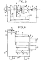
- a lens 8 is placed in contact with an optical fiber 10 which emits light and whose axis is coincident with a reference axis xx '.
- the lens 8 is designed in such a way that it transforms the light beam emitted by the optical fiber 10 into a practically parallel beam F of diameter D 2 .
- the lens 8 may thus be a rod lens or an index gradient lens.
- a reference piece 6 having a circular opening 6 '.
- the circular opening 6 ' is coaxial with the optical fiber 10 and is placed in front of a photo-detector 7.
- the diameter D 1 of the opening 6' being chosen to be less than the diameter D 2 of the beam F which strikes the reference part 6 , the energy received by the photodetector 7 will be dependent on the relative position of the optical axis of the lens 8 relative to that of the reference axis xx 'common to the optical fiber 10 and to the calibrated hole 6' . In fact, the photo-detector 7 will receive a maximum quantity of light energy when the axis of the lens 8 coincides with the reference axis xx '.
- the lens will therefore be displaced along two axes yy 'and zz' perpendicular to the axis xx 'until a maximum of light is obtained at the level of the photo-detector 7, this corresponding to the alignment of the axis of the optical fiber 10 with the optical axis of the lens 8.
- FIG. 1b represents the distribution of the light energy I of the beam F in a direction perpendicular to the axis xx '.
- the curve obtained is conventionally a Gaussian of width D 2 . It was found that a maximum sensitivity of the adjustment of the position of the lens was obtained for a diameter D of the calibrated hole 6 'equal to the width at half height of the Gaussian.
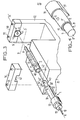
- a tip 1 in which an optical fiber 10 has been positioned is itself positioned in a V-shaped groove 40.
- the V-shaped groove 40 can be used to carry out the in situ mounting of the fiber 10 in the end piece 1, by virtue of the addition of a centering device in the groove 40, for example shims making it possible to define a second V, the bottom of which is located so that a fiber which rests in said second V has its axis coincident with the reference axis xx 'on which the subsequent alignments must take place.
- a centering device in the groove 40 for example shims making it possible to define a second V, the bottom of which is located so that a fiber which rests in said second V has its axis coincident with the reference axis xx 'on which the subsequent alignments must take place.
- a ring 2 is intended to receive the lens 8 to be centered.
- the V-shaped groove 40 is disposed in a first plate 21 of a centering block 20 including a second plate 22, separated from the first by an opening 23 has at its upper part a V-shaped groove 41 which is the extension of the groove 40.
- the ring 6 behind which is the photodetector 7.
- the signals from the photodetector 7 are analyzed by a measurement circuit 13.
- a micro-manipulator 4 having a clamp 3 in which is blocked one end 9 of the lens 8 projecting from the ring 2.
- the axis of the clamp 3 is parallel to the axis xx 'so that the geometric axis of the lens 8, itself in principle parallel to its optical axis, ie always parallel to the axis xx '.
- the ring 2 has at its upper part a bore 11 allowing, when the centering of the lens has been achieved, to fix the position of the latter, as well as that of the front end of the end piece 1, with an adhesive 15.
- the end piece 1 comprises a front cylindrical part 30 comprising a V-shaped profile 31 corresponding to that of the groove 40, and continuing forwards by a cylindrical extension 30 'comprising a hole 32 in which glue has now been introduced now in position the fiber 10, the front end of which is flush with the end 30 "of the end piece.
- the end piece 1 also has a flange 33 which serves as a stop on the lateral face of the extension 21
- the fiber 10 emerges at the rear of the end piece 1 through a hole 35 formed in a rear cylindrical part 34.
- the end piece 1 is held in position by a flange 36 having at its lower part a rectangular opening 42 intended to hold the front cylindrical part 30.
- the flange 36 is held in place by screws 39 which are screwed into threads 42 formed in the upper face of the plate 21 on either side of the groove 40.
- the ring 2 is of generally cylindrical shape. It has a longitudinal bore 43 of diameter greater than that of the cylindrical extension 30 '.
- the ring 2 does not need to be held in position since it only has the function of fixing the relative position of the lens 8 and the optical fiber 1, bonding by introducing index glue being provided by injection through the bore 11.
- the inside diameter of the ring 2 is advantageously substantially greater than the outside diameter of the end 30 ′ of the end piece 1 and / or the outside diameter of the lens 8 so as to facilitate alignment and bonding operations.
- the reference piece 6 is positioned in the groove 41 located in the extension of the groove 40 so that the axis of its calibrated hole 6 'is located on the reference axis xx' with which the optical fiber 10 is also aligned.
- the centering piece 6 is held in place by a flange 38 provided with a support plane 44 of the centering piece 6.
- the flange 38 is held in place by screws 39.
- FIG. 4 shows a variant of the connector element in which the ring 2, cylindrical of revolution, has its outside diameter completely inscribed in the contour of the front cylindrical part 30 and of the V-shaped profile 31, so that during assembly of the connector element, the V-profile 31 is free and can exercise its assembly surface function without complication of assembly.
- the ring 2 can be held in the V 40 by wedges or else be centered by the cylindrical extension 30 '.
- the micro-manipulator comprises a plate 31.
- An L-shaped part 52 is integral with this plate and it has a horizontal portion 53 and a vertical wall 54, the latter carrying a system of three-jaw chucks d 'horizontal axis.
- This system comprises an axis 56 fixed by a flange 55 on the wall 54, as well as a thread 57 on which is fitted a plug 58 allowing the clamping of the three jaws 59.
- the end 9 of the lens 8 which protrudes ring 2 is locked by tightening in the three jaws 59.
- the plate 51 can be moved parallel to the axis xx 'as well as to a horizontal axis yy' orthogonal thereto as well as vertically along the axis zz '.
- the plate 51 is associated with a plate 66 whose movement is controlled along one of the aforementioned axes by a vernier 63 and which is itself connected to slides 64 and 65 whose displacement is controlled by verniers 61 and 62 along the two other directions mentioned above.
- the centering piece 20 has an extension 67 whose upper face 70 serves as a reference surface for the movement of the plates of the micro-manipulator. In other words, the face 70 is machined so as to be strictly parallel to the axis of the grooves 40 and 41.
- the lens 8 is slid into the bore 8 'of the ring 2. It is then slid and then locked between the three jaws of the micro-manipulator which has been pre-positioned for this purpose.
- the end piece 1 is then placed in the groove 40 and fixed in position by the flange 36.
- the micro-manipulator is then actuated so as to move the lens 8 along the axis xx 'so that the end of the rod lens 8 located on the side of the optical fiber 10 comes practically into contact with the latter.
- This operation can be carried out visually under binocular, or by moving the lens 8 until it comes mechanically into contact with the end of the end piece 1 and then moving it back so as to leave a space between the lens 8 and the fiber 10 such that the end of the optical fiber 10 is found in the focal plane of the rod lens 8.
- This remaining interval will also make it possible to subsequently move the lens 8 horizontally parallel to the axis yy 'and vertically parallel to the axis zz' without there being friction between these two optical elements.
- the distance between the fiber 10 and the lens 8 provides only a very weak weakening of the transmitted light, since the lens 8 will receive almost all of the diverging light emitted by the fiber according to a cone whose angle depends on the digital aperture of the fiber.
- the micro-manipulator is then actuated along one of the two axes yy 'or zz' until a maximum of light is detected by the cell 7.
- the lens 8 is a rod lens
- the hole calibrated 6 ' has a diameter of 1 mm and is located at a distance of 40 mm from the exit face of the lens 8.
- the micro-manipulator is positioned on this maximum and the lens 8 is moved in the other direction zz' or yy 'until another maximum is obtained. This process can possibly be iterated as much as necessary until the positioning of the lens is correct.
- index glue is introduced through the opening 11 so as to fix this position.
- the jaw 59 and the flange 36 will be loosened after the adhesive has solidified. In this way, the optical axis of the lens 8 will have been placed in coincidence with the axis of the optical fiber 10.
- the V-shaped profile 31 can serve as a reference surface for the subsequent mounting of the fiber assembly- lens in which the fiber and the lens are precisely positioned once and for all.
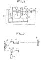
- the location of the axis of the lens 8 is performed not by transmission, but by reflection.
- a mirror 72 is arranged perpendicular to the reference axis along which the fiber 10 is positioned in its end piece 1 when the latter is placed in the V-shaped groove 40.
- the light thus returned in the fiber 10 is derived by a coupler 75 to a photo-detector 77.
- the coupler 75 is also arranged so as to allow the light emitted by the source 12 to pass through.
- it may for example comprise a semi-reflecting mirror 78.
- the system (7, 38, 4 ′, 50) of FIG. 5 is replaced by a mirror 72 pressed against a reference wall 73 perpendicular to the axis of the fiber 10 when its tip is disposed in the groove 40.
- the centering operations of the lens can be carried out in the same way as for the embodiment using a calibrated hole, and the maximum of light returned into the fiber is obtained when the axis of the optical fiber 10 is aligned with the optical axis of the lens 8.
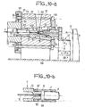
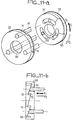
- FIGS. 9a, 9b, 10a and 10b represent a device adapted to the implementation of the invention in the case of a cylindrical end-piece and which makes it possible on the one hand to mount the fiber in the end-piece , and secondly the centering of the lens relative to the fiber, the assembly being fixed in position by index glue.
- the inner diameter of the ring is advantageously chosen to be substantially greater than the outside diameter of the end 30 ′ of the end piece II and / or the outside diameter of the lens 8.
- the device comprises a plate 95 arranged on a rigid base 108.
- the plate has a central opening having a cylindrical portion 109 which is extended by a frustoconical portion 105, which is coaxial with it and which widens as the distance with the cylindrical portion 109 increases.
- the axis common to these two portions is the reference axis xx ′ for the alignment of the optical fiber and the lens.
- FIG. 9a shows the device with its elements positioned with a view to carrying out the first operation consisting in centering the fiber 10 in the cylindrical end piece 1 '.
- the latter is held in position by the jaws 91 of a gripper 90 with three jaws.
- the clamp 90 has a cylindrical rear portion 92.
- Each of the jaws 91 is provided with an inclined external profile 91 'so that, when the clamp 90 is closed on the cylindrical end piece l', these inclined profiles 91 'form with the axis of the forceps an angle equal to the half-angle of opening of the frustoconical portion 105, which therefore serves as a positioning reference for the forceps which centers the cylindrical end piece l 'along the reference axis xx'.
- the fitting of the end piece is made possible thanks to the cooperation of a thread 92 ′ formed in the cylindrical rear part 92 and of a nut 93.
- a cylindrical positioner 98 split into 98 ′ and provided with a central opening with a diameter slightly greater than that of the fiber 10 and coaxial with the external surface of the positioner 98 is put in place by a second clamp 96 introduced at the level of the flared part of the frustoconical portion 105.
- the clamp 96 has three jaws 97 each of which is provided with an inclined external profile 97 ', so that, when the clamp 96 is closed on the cylindrical positioner 98, these inclined profiles 91' form with the axis of the forceps an angle equal to the half-angle of opening of the frustoconical portion 105, which also serves as a positioning reference for the forceps.
- the clamp centers the cylindrical positioner 98 along the reference axis xx 'while ensuring elastic clamping of the end 10' of the fiber 10 which protrudes from the end piece 1 '. This elasticity function is fulfilled by the slot 98.
- the clamps 90 and 96 cooperate with the frustoconical portion 105 which guarantees maximum coaxiality of the end piece and the fiber.
- the clamp 96 is secured at its rear part to a centering flange 99 on which are rigidly mounted at one of their ends three tie rods 101 passing longitudinally through the plate 95 and the opposite end of which is secured to a locking flange 102.
- the locking flange 102 has a central opening 109 allowing free passage to the nut 93.
- the locking flange 102 (see FIGS. 1a and 11b) carries inclined ramps 111 intended to cooperate with corresponding ramps 112 formed in a locking nut 103 provided with a central opening 110 allowing free passage to the nut 93.
- L lock nut 103 carried by a flat face 113 on the flat rear face 114 of the plate 95.
- the tie rods 101 pass through the lock nut 112 at the grooves 117 allowing the free rotation of the lock nut 117 according to a angular travel allowing the cooperation of the ramps.
- the nut 93 is loosened and pushed into abutment on the rear face in place 114 of the plate 95.
- the end piece is slid between the jaws 91 and the nut 93 is tightened until it locks.
- the inclined outer profiles 91 ′ of the jaws 91 bear over their entire length on the frusto-conical portion 105 and the axis of the nozzle l ′ is aligned with the axis of the clamp which coincides with the axis xx ′ of the frustoconical part 105.
- the positioner 98 is put in place without effective clamping between the jaws 97. It is pre-positioned sufficiently so that its central opening is sufficiently aligned with the end piece l 'so that an end 10' of the fiber 10 can pass freely through its central opening.
- the locking nut 103 is then tightened (rotation in the direction of the arrow F I ) so as to elastically tighten the end 10 ′ of the fiber 10 in the positioner 98.
- a third phase (see FIG. 10a), the ring 2 is put in place with the clamp 96 around the cylindrical end 30 'of the end piece 1'.
- the internal diameter of the ring 2 can be greater than the diameter of the end 30 ′ since the ring 2 only serves for the mechanical connection of the end piece 1 ′ and of the lens 8, and does not fulfill any function centering.
- the lens 8 is then presented inside the ring 2 thanks to the micro-manipulator 3 and in the same way as for the example in the figure. 3.
- the centering of the lens is also carried out in the same way, by a maximum method. This is the variant of Figures 7 and 8, using a mirror 72, which is illustrated here.
- an index glue is introduced through the opening 11 of the ring 2 so as to permanently freeze the position of the lens 8 relative to the optical fiber.
- the fourth phase consists in disengaging the micromanipulator, then the clamp 96 after solidification of the glue, after which the clamp 90 is also unlocked so as to disengage the end-piece fitted with the lens 8.
- the ring 2 has an outside diameter smaller than that of the cylindrical part 30. This characteristic is also advantageous in that it allows a subsequent mounting of the end fitting equipped with it from the rear, the centering of the fitted end fitting being carried out relative to the cylindrical part 30 which serves as a reference.
Landscapes
- Physics & Mathematics (AREA)
- General Physics & Mathematics (AREA)
- Optics & Photonics (AREA)
- Optical Couplings Of Light Guides (AREA)
Applications Claiming Priority (2)
| Application Number | Priority Date | Filing Date | Title |
|---|---|---|---|
| FR8309654A FR2547425B1 (fr) | 1983-06-10 | 1983-06-10 | Procede et dispositif de centrage relatif d'une fibre optique et d'une lentille dans un embout, et element de connecteur ainsi obtenu |
| FR8309654 | 1983-06-10 |
Publications (2)
| Publication Number | Publication Date |
|---|---|
| EP0129456A2 true EP0129456A2 (de) | 1984-12-27 |
| EP0129456A3 EP0129456A3 (de) | 1987-12-02 |
Family
ID=9289670
Family Applications (1)
| Application Number | Title | Priority Date | Filing Date |
|---|---|---|---|
| EP84401055A Withdrawn EP0129456A3 (de) | 1983-06-10 | 1984-05-22 | Verfahren und Vorrichtung zur Zentrierung einer optischen Faser relativ zu einer Linse in einem Stecker und so erhaltenes Verbindungselement |
Country Status (2)
| Country | Link |
|---|---|
| EP (1) | EP0129456A3 (de) |
| FR (1) | FR2547425B1 (de) |
Cited By (3)
| Publication number | Priority date | Publication date | Assignee | Title |
|---|---|---|---|---|
| FR2591761A1 (fr) * | 1985-12-12 | 1987-06-19 | Socapex | Ensemble de collimation deconnectable |
| FR2593928A1 (fr) * | 1986-01-24 | 1987-08-07 | Souriau & Cie | Procede et appareillage pour positionner et immobiliser une terminaison de fibre optique dans un embout de connexion, embout de connexion et connecteur optique ainsi realises |
| WO2002070987A1 (en) * | 2001-03-01 | 2002-09-12 | Corning Incorporated | System and method of aligning two optical axis towards each other |
Family Cites Families (5)
| Publication number | Priority date | Publication date | Assignee | Title |
|---|---|---|---|---|
| JPS5250248A (en) * | 1975-10-20 | 1977-04-22 | Nippon Telegr & Teleph Corp <Ntt> | Manufacturing method of connectors for optical fibers and apparatus th erefore |
| US4290667A (en) * | 1976-02-03 | 1981-09-22 | International Standard Electric Corporation | Optical fibre terminations and connectors |
| DE2654537C2 (de) * | 1976-12-02 | 1982-10-21 | Licentia Patent-Verwaltungs-Gmbh, 6000 Frankfurt | Verfahren zur Zentrierung einer Lichtleitfaser in einem zylindrischen Steckerstift für eine lösbare Steckverbindung |
| DE2906104C3 (de) * | 1979-02-17 | 1981-11-26 | Harting Elektronik Gmbh, 4992 Espelkamp | Vorrichtung zum Kopppeln zweier Lichtwellenleiter |
| DE3141904A1 (de) * | 1981-10-22 | 1983-06-30 | Felten & Guilleaume Fernmeldeanlagen GmbH, 8500 Nürnberg | Steckverbinder fuer lichtwellenleiter |
-
1983
- 1983-06-10 FR FR8309654A patent/FR2547425B1/fr not_active Expired
-
1984
- 1984-05-22 EP EP84401055A patent/EP0129456A3/de not_active Withdrawn
Cited By (7)
| Publication number | Priority date | Publication date | Assignee | Title |
|---|---|---|---|---|
| FR2591761A1 (fr) * | 1985-12-12 | 1987-06-19 | Socapex | Ensemble de collimation deconnectable |
| EP0226059A3 (en) * | 1985-12-12 | 1987-10-21 | Socapex S.A. | Disconnectable collimation assembly |
| US4776663A (en) * | 1985-12-12 | 1988-10-11 | 501 Socapex S.A. | Disconnectable collimation assembly |
| FR2593928A1 (fr) * | 1986-01-24 | 1987-08-07 | Souriau & Cie | Procede et appareillage pour positionner et immobiliser une terminaison de fibre optique dans un embout de connexion, embout de connexion et connecteur optique ainsi realises |
| EP0234990A1 (de) * | 1986-01-24 | 1987-09-02 | Souriau Et Cie | Verfahren und Vorrichtung zum Positionieren und Fixieren eines optischen Faserendstücks in einem Verbindungsstecker und derartig realisierter Stecker und optische Verbindung |
| US4815811A (en) * | 1986-01-24 | 1989-03-28 | Sourtau & Cie | Method and apparatus for positioning and fixing an optic fibre termination in a connector, a connection terminal and an optic connector |
| WO2002070987A1 (en) * | 2001-03-01 | 2002-09-12 | Corning Incorporated | System and method of aligning two optical axis towards each other |
Also Published As
| Publication number | Publication date |
|---|---|
| FR2547425A1 (fr) | 1984-12-14 |
| EP0129456A3 (de) | 1987-12-02 |
| FR2547425B1 (fr) | 1987-04-10 |
Similar Documents
| Publication | Publication Date | Title |
|---|---|---|
| EP0126003B1 (de) | Verfahren und Vorrichtung für eine Verbindung zwischen einer optischen Faser und einer integrierten optischen Komponente mit einem Wellenleiter | |
| EP0597771B1 (de) | Überwachungseinrichtung zur optischer Bündelzentrierung, Verwendung zur Bündeleinführung in optische Faser | |
| EP0000145B1 (de) | Verbindung für Lichtleitfasern und Verfahren zum Anschluss einer Lichtleitfaser an eine Verbindung | |
| EP0158561A2 (de) | Verbindungsvorrichtung für eine optische Faser und eine Photoelement, Empfänger oder Sender; Verfahren zur Einstellung solcher Elemente | |
| EP0205359A1 (de) | Optoelektronischer Zweirichtungsbauteil, der einen optischen Koppler bildet | |
| EP0603042A1 (de) | Monolithisches System zur Kopplung zwischen einer optischen Faser und optoelektronischem Bauteil | |
| CA1250465A (fr) | Commutateur pour circuit a guide de lumiere | |
| FR2503388A1 (fr) | Embout de connecteur pour fibre optique, procede de centrage d'une fibre dans cet embout et dispositif pour la mise en oeuvre de ce procede | |
| FR2611388A1 (fr) | Module optique actif pour embase de connecteur | |
| EP0045271B1 (de) | Verbindung für optische Fasern | |
| EP0018873B1 (de) | Kompakte optische Koppelungsvorrichtung und solch eine Vorrichtung enthaltender interferometrischer Gyrometer mit einer optischen Faser | |
| FR2588387A1 (fr) | Element de connecteur hermaphrodite pour fibres optiques | |
| CA1257994A (fr) | Piece de reception a fibre optique pour dispositif de couplage et procede de realisation d'un tel dispositif | |
| EP0129456A2 (de) | Verfahren und Vorrichtung zur Zentrierung einer optischen Faser relativ zu einer Linse in einem Stecker und so erhaltenes Verbindungselement | |
| FR2591761A1 (fr) | Ensemble de collimation deconnectable | |
| EP0011012B1 (de) | Zentriervorrichtung für eine optische Faser in einer Zwinge und Zwinge mit einer optischem Faser die mit dieser Vorrichtung zentriert worden ist | |
| CA3128728C (fr) | Injection d'un faisceau de rayonnement dans une fibre optique | |
| EP0096608B1 (de) | Faseroptischer Kollimator, Anwendung zur Realisierung optischer Schaltervorrichtungen | |
| EP0768548B1 (de) | Gerät zum Erleichtern der Herstellung optischer Faserverbindungen | |
| FR2780167A1 (fr) | Dispositif pour produire des faisceaux de rayons paralleles collimates a partir de diodes laser a couplage de fibres et procede de fabrication de ce dispositif | |
| EP1499916A1 (de) | Verbesserte optoelektronische koppeleinrichtung | |
| EP1516218A2 (de) | Einrichtung zum automatischen zentrieren eines laserstrahls und verfahren zu ihrer herstellung | |
| FR2533323A1 (fr) | Dispositif attenuateur optique variable | |
| EP0462881B1 (de) | Wand zur Abtrennung zweier Bereiche mit einer Vorrichtung zur Verbindung von zwei optischen Fasern | |
| EP0197841A1 (de) | Optischer Duplexer mit einer integrierten optischen halbpermanenten Verbindung |
Legal Events
| Date | Code | Title | Description |
|---|---|---|---|
| PUAI | Public reference made under article 153(3) epc to a published international application that has entered the european phase |
Free format text: ORIGINAL CODE: 0009012 |
|
| AK | Designated contracting states |
Designated state(s): DE GB IT |
|
| PUAL | Search report despatched |
Free format text: ORIGINAL CODE: 0009013 |
|
| AK | Designated contracting states |
Kind code of ref document: A3 Designated state(s): DE GB IT |
|
| 17P | Request for examination filed |
Effective date: 19880524 |
|
| STAA | Information on the status of an ep patent application or granted ep patent |
Free format text: STATUS: THE APPLICATION IS DEEMED TO BE WITHDRAWN |
|
| 18D | Application deemed to be withdrawn |
Effective date: 19901203 |
|
| RIN1 | Information on inventor provided before grant (corrected) |
Inventor name: MALINGE, JEAN-LOUIS Inventor name: CLEMENT, PATRICK Inventor name: BOUYGUES, JEAN |