EP0129510B1 - Haltevorrichtung für eine Garnspule - Google Patents
Haltevorrichtung für eine Garnspule Download PDFInfo
- Publication number
- EP0129510B1 EP0129510B1 EP19840810273 EP84810273A EP0129510B1 EP 0129510 B1 EP0129510 B1 EP 0129510B1 EP 19840810273 EP19840810273 EP 19840810273 EP 84810273 A EP84810273 A EP 84810273A EP 0129510 B1 EP0129510 B1 EP 0129510B1
- Authority
- EP
- European Patent Office
- Prior art keywords
- plate
- base
- pawl
- stop
- holding device
- Prior art date
- Legal status (The legal status is an assumption and is not a legal conclusion. Google has not performed a legal analysis and makes no representation as to the accuracy of the status listed.)
- Expired
Links
- 230000000694 effects Effects 0.000 description 2
- 238000003466 welding Methods 0.000 description 2
- 206010053567 Coagulopathies Diseases 0.000 description 1
- 230000004323 axial length Effects 0.000 description 1
- 230000035602 clotting Effects 0.000 description 1
- 238000003780 insertion Methods 0.000 description 1
- 230000037431 insertion Effects 0.000 description 1
- 238000009940 knitting Methods 0.000 description 1
- 239000004753 textile Substances 0.000 description 1
- 230000007704 transition Effects 0.000 description 1
Images

Classifications
-
- D—TEXTILES; PAPER
- D02—YARNS; MECHANICAL FINISHING OF YARNS OR ROPES; WARPING OR BEAMING
- D02H—WARPING, BEAMING OR LEASING
- D02H1/00—Creels, i.e. apparatus for supplying a multiplicity of individual threads
-
- B—PERFORMING OPERATIONS; TRANSPORTING
- B65—CONVEYING; PACKING; STORING; HANDLING THIN OR FILAMENTARY MATERIAL
- B65H—HANDLING THIN OR FILAMENTARY MATERIAL, e.g. SHEETS, WEBS, CABLES
- B65H49/00—Unwinding or paying-out filamentary material; Supporting, storing or transporting packages from which filamentary material is to be withdrawn or paid-out
- B65H49/02—Methods or apparatus in which packages do not rotate
- B65H49/04—Package-supporting devices
- B65H49/06—Package-supporting devices for a single operative package
-
- B—PERFORMING OPERATIONS; TRANSPORTING
- B65—CONVEYING; PACKING; STORING; HANDLING THIN OR FILAMENTARY MATERIAL
- B65H—HANDLING THIN OR FILAMENTARY MATERIAL, e.g. SHEETS, WEBS, CABLES
- B65H2701/00—Handled material; Storage means
- B65H2701/30—Handled filamentary material
- B65H2701/31—Textiles threads or artificial strands of filaments
Definitions
- the invention relates to a device for holding a yarn spool, from the sleeve of which protrudes at least one annular edge.
- Coil sleeves of this type usually consist of cardboard or plastic, have different diameters and a cylindrical or conical shape.
- bobbins of thread are held in a creel and the threads drawn from the bobbins are fed to the processing machine.
- creels are used, for example, in looms, knitting machines, twisting machines, texturing machines and bobbin machines and in warping.
- the invention has for its object to provide a structurally simple holding device for bobbins. It is to a clotting possible - have ge height in the direction of the coil axis and be able to both cylindrical, such as conical bobbin tubes to hold different size.
- the overall height of the device in the direction of the spool axis should be as small as possible so that the spools can be arranged close to one another. In addition, adjacent gates can then be placed closer together.
- a universal usability of the holder for large and small spools of thread with a conical and cylindrical sleeve is also of great economic importance. If one had to replace the coil holders of the gates because of a transition to coils from another manufacturer, in which differently dimensioned sleeves are used, this would entail enormous costs.
- the invention makes use of this knowledge and provides a solution for a yarn turkey device that meets the requirements described above.
- the device according to the invention for holding a yarn package has the features mentioned in the characterizing part of claim 1. Due to the one-sided clamping holder of the sleeve, the overall height of the device in the axial direction of the yarn package can be low.
- No bobbin holder of known type has the simple self-locking clamping of the sleeve edge of the holder according to the invention, nor can the advantages mentioned be achieved with them.
- the known coil holders clamp the coil sleeve from the inside.
- the bobbin holder known from US Pat. No. 3,850,394 can hold yarn bobbins of different sizes, but has a height that even exceeds the axial length of the bobbin.
- the US-PS-1 022 283 shows a coil holder, which has a low overall height, but can only hold a coil with a conical sleeve that is precisely adapted to the holder.
- the holder is held here by the fit of the sleeve on the truncated cone of the holder, which is supported by spring force.
- the empty sleeve can be easily removed from the holder against the holding force. (see page 1, lines 96-98 of the US patent)
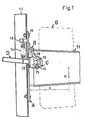
- the main components of the holding device according to FIG. 1 are a base plate A with a clamping part B protruding from the front and firmly connected to the base plate by spot welding, and a second clamping part C pivotably connected to the base plate.
- Clamping part C is held between two L-shaped bearing parts 10 connected to the base plate A and can be pivoted about the bearing pin 11.
- Clamping part C consists of a roundel with an upwardly projecting clamping tongue 18 and a release lever D fastened to the roundel and projecting backwards.
- the release lever D passes through a slot 12, the bearing plate A.
- a rearward projecting bolt 13 is attached above the lever D. Between the bolt 13 and the lever D, a tension spring 14 is attached, which tends to pivot the clamping part C clockwise.
- the upper edge of the slot 10 forms a stop for the lever D.
- the bearing pin 11 is held on both sides of the bearing parts 10 externally attached circlips 15.
- the holding device as a whole is fastened by means of the screws 16 to a vertical strut 17 of a gate, which is provided with a corresponding opening for this purpose.
- the protruding part of the clamping part B is slightly inclined downwards. In the rest position, the tongue 18 of the clamping part C projects upwards, is inclined a little backwards, without touching the clamping part B.
- Figure 1 shows the sleeve H during insertion into the holding device. The fully inserted position is shown with broken lines.
- the yarn supply wound on the sleeve H is indicated by the dash-dotted outline G.
- the sleeve is held at the top between the clamping parts B and C and is supported at the bottom at a point diametrically opposite the clamping point. the base plate A from.
- the weight of the thread spool therefore generates a tilting moment K. x, and a tension is created at the clamping point, which, as mentioned above, increases the clamping effect.
- Figures 2 and 3 show a variant of the device which is particularly suitable for holding particularly heavy and large bobbins.
- the bearing parts for the clamping part C are extended so that they protrude further against the base plate A.
- the sleeve is clamped between the clamping parts B and C as before, but is also on the extended bearing parts. This reduces the overturning moment to the value K, - y and the tension exerted on the clamping point is considerably reduced.
- FIGS. 2 and 3 parts which correspond to those in FIG. 1 are provided with the same reference numbers.
- the bearing parts 10 'projecting further towards the front are connected to the back of the bearing plate A by spot welding points and protrude forwards through an opening 12'.
- the front end is provided with a support projection 10 ".
- the pivotable clamping part C ' has the shape of a U-shaped part with a protruding lip 18.
- a torsion spring 20 is provided.
- the fixed clamping part B is provided with sharp-edged ribs running parallel to the base plate.
Landscapes
- Engineering & Computer Science (AREA)
- Textile Engineering (AREA)
- Storage Of Web-Like Or Filamentary Materials (AREA)
- Unwinding Of Filamentary Materials (AREA)
- Warping, Beaming, Or Leasing (AREA)
Description
- Die Erfindung bezieht sich auf eine Vorrichtung zum Halten einer Garnspule, von deren Hülse mindestens ein ringförmiger Rand vorsteht. Derartige Spulenhülsen bestehen meist aus Karton oder Kunststoff, haben unterschiedliche Durchmesser und eine zylindrische oder konische Form. Die voll bewickelte Hüise, das heisst die Garnspule hat dementsprechend ebenfalls eine konische oder zylindrische Aussenkontur.
- In der Textilindustrie wird eine Vielzahl solcher Garnspulen in einem Gatter gehalten und die von den Spulen abgezogenen Fäden der Verarbeitungsmaschine zugeführt. Derartige Gatter kommen beispielsweise zur Anwendung bei Webstühlen, Strickmaschinen, Zwirnmaschinen, Texturiermaschinen sowie Spulenmaschinen und bei der Kettenbildung.
- Bei bisher bekannten Gattern werden die Garnspulen auf relativ lange Zapfen aufgesetzt. Für die Bedienung ist dies bei nahe nebeneinander stehenden Gattern beschwerlich, weil der Raum zwischen den Gattern sehr eng ist. Aus diesem Grunde hat man die Zapfen schwenkbar gemacht. Dies bringt die Gefahr mit sich, dass der Zapfen nicht ganz in seine Ausgangslage zurückgebracht wird, was eine unerwünschte Erhöhung der Fadenspannung zur Folge hat.
- Die Erfindung stellt sich zur Aufgabe, eine konstruktiv einfache Haltevorrichtung für Garnspulen zu schaffen. Sie soll eine möglichst gerin- ge Bauhöhe in Richtung der Spulenachse aufweisen und im Stande sein, sowohl zylindrische wie konische Spulenhülsen verschiedener Grösse zu halten. Die Bauhöhe der Vorrichtung in Richtung der Garnspulenachse sollte möglichst klein sein, damit die Garnspulen nahe beieinander angeordnet werden können. Zudem können dann benachbarte Gatter näher beieinander aufgestellt werden.
- Dies ist von eminenter wirtschaftlicher Bedeutung, wenn man bedenkt, dass hunderte von Spulen auf einem Gatter gehalten werden müssen.
- Eine universelle Brauchbarkeit des Halters für grosse wie kleine Garnspulen mit konischer wie zylindrischer Hülse ist ebenfalls von grosser wirtschaftlicher Bedeutung. Müsste man die Spulenhalter der Gatter wegen einem Uebergang auf Spulen eines andern Fabrikats, bei dem anders dimensionierte Hülsen verwendet werden, auswechseln, würde dies enorme Kosten verursachen.
- Da in den meisten Gattern die Garnspulen mit ihrer Längsachse von vertikal stehend bis horizontal geneigt gehalten werden, genügt es, den vorstehenden Rand der Spulenhülse an einer Stelle festzuklemmen, wenn der diametral gegenüberliegende Hülsenrand abgestützt wird.
- Von dieser Erkenntnis macht die Erfindung Gebrauch und gibt eine Lösung für eine Garnsputenhattevorrichtung an, die den oben geschilderten Anforderungen genügt.
- Die erfindungsgemässe Vorrichtung zum Halten einer Garnspule weist die im kennzeichnenden Teil des Anspruchs 1 genannten Merkmale .auf. Durch die einseitige Klemmhalterung der Hülse kann die Bauhöhe der Vorrichtung in Achsrichtung der Garnspule gering sein.
- Für besonders grosse und schwere Garnspulen ist es von Vorteil, eine zusätzliche Auflage für die Hülse zu schaffen, wie dies aus der nachfolgenden Beschreibung hervorgeht. Die Bauhöhe wird dadurch nur geringfügig vergrössert.
- Kein Spulenhalter bekannter Art weist die einfache selbsthemmende Klemmung des Hülsenrandes des erfindungsgemässen Halters auf, noch lassen sich mit ihnen die erwähnten Vorteile erreichen. Die bekannten Spulenhalter klemmen die Spulenhülse von innen her.
- Der aus der US-PS-3 850 394 bekannte Spulenhalter kann zwar Garnspulen unterschiedlicher Grösse halten, hat aber eine Bauhöhe, die die axiale Länge der Spule sogar noch übersteigt.
- Die US-PS-1 022 283 zeigt einen Spulenhalter, der zwar eine geringe Bauhöhe aufweist, dafür aber nur eine Spule mit einer dem Halter genau angepassten konischen Hülse zu halten vermag. Die Halterung erfolgt hier durch den Passitz der Hülse auf dem Kegelstumpf des Halters, der durch Federkraft unterstützt wird. Die leere Hülse lässt sich entgegen der Haltekraft einfach vom Halter abziehen. (siehe hierzu Seite 1, Zeilen 96-98 der US-Patentschrift)
- In der Zeichnung sind zwei Ausführungsbeispiele des Erfindungsgegenstandes dargestellt.
- Es zeigen :
- Figur 1 eine Haltevorrichtung in Seitenansicht und teilweise im Schnitt ;
- Figur 2 eine Variante der Vorrichtung nach Figur 1 und
- Figur 3 eine Ansicht der Vorrichtung nach Figur 2 von oben.
- Die Hauptbestandteile der Haltevorrichtung nach Figur 1 sind eine Grundplatte A mit einem vorderseitig vorstehenden, durch Punktschweissen fest mit der Grundplatte verbundenen Klemmteil B und einem zweiten schwenkbar mit der Grundplatte verbundenen Klemmteil C.
- Klemmteil C ist zwischen zwei L-förmigen mit der Grundplatte A verbundenen Lagerteilen 10 gehalten und um den Lagerbolzen 11 schwenkbar.
- Klemmteil C besteht aus einem Rondell mit einer nach oben ragenden Klemmzunge 18 und einen am Rondell befestigten nach hinten ragenden Lösehebel D.
- Der Lösehebel D durchsetzt einen Schlitz 12, der Lagerplatte A.
- An der Rückseite der Grundplatte A ist oberhalb des Hebels D ein nach hinten ragender Bolzen 13 befestigt. Zwischen den Bolzen 13 und dem Hebel D ist eine Zugfeder 14 angebracht, die das Bestreben hat, den Klemmteil C in Uhrzeigersinn zu schwenken.
- Der obere Rand des Schlitzes 10 bildet einen Anschlag für den Hebel D.
- Der Lagerbolzen 11 ist mittels beidseitig der Lagerteile 10 aussen angebrachten Sicherungsringen 15 gehalten.
- Die Haltevorrichtung als Ganzes ist mittels den Schrauben 16 an einer vertikalen Strebe 17 eines Gatters befestigt, die dazu mit einem entsprechenden Durchbruch versehen ist.
- Die vorstehende Partie des Klemmteiles B ist ein wenig nach unten geneigt. In Ruhestellung ragt die Zunge 18 des Klemmteiles C nach oben, ein wenig nach rückwärts geneigt, ohne den Klemmteil B zu berühren.
- Wird nun die Hülse H einer Garnspule etwa senkrecht zur Grundplatte A auf die Zunge 18 des Klemmteiles C gedrückt, schwenkt diese im Gegenuhrzeigersinn und die Feder 14 hält die freie Randpartie der Hülse zwischen dem Klemmteil B und der Zunge 18 des Klemmteiles C fest.
- Dadurch, dass die Schwenkachse 11 vor der Klemmstelle liegt, verstärkt das Gewicht der Garnspule die Klemmwirkung.
- Figur 1 zeigt die Hülse H während des Einschiebens in die Haltevorrichtung. Mit unterbrochenen Linien ist die voll eingeschobene Lage dargestellt..
- Der auf der Hülse H aufgewickelte Garnvorrat ist durch die strichpunktierte Umrisslinie G angedeutet.
- Bei dieser Haltevorrichtung ist die Hülse oben zwischen den Klemmteilen B und C gehalten und stützt sich unten an einer der Klemmstelle diamentral gegenüberliegenden Stelle auf. der Grundplatte A ab. Das Gewicht der Garnspule erzeugt daher ein Kippmoment K. x, und es entsteht an der Klemmstelle ein Zug, der wie oben erwähnt, die Klemmwirkung vergrössert.
- Bei sehr schweren und grossen Spulen könnte sich trotzdem die Hülse aus der Klemmung losreissen.
- Die Figuren 2 und 3 zeigen eine Variante der Vorrichtung, die insbesondere zum Halten von besonders schweren und grossen Garnspulen geeignet ist. Hier sind nämlich die Lagerteile für den Klemmteil C verlängert, sodass sie weiter gegen die Grundplatte A vorstehen.
- Die Hülse wird wie bisher zwischen den Klemmteilen B und C festgeklemmt, liegt aber zusätzlich auf den verlängerten Lagerteilen auf. Dadurch verringert sich das Kippmoment auf den Wert K, - y und der auf die Klemmstelle ausgeübte Zug wird dadurch erheblich verringert.
- In den Figuren 2 und 3 sind Teile, die denjenigen der Figur 1 entsprechen, mit gleichen Bezugszahlen versehen. Die weiter nach vorne ausladenden Lagerteile 10' sind an der Rückseite der Lagerplatte A durch Punktschweissstellen mit derselben verbunden und ragen durch eine Oeffnung 12' nach vorne. Das vordere Ende ist mit einem Auflage-Vorsprung 10" versehen.
- Der schwenkbare Klemmteil C' hat die Form eines U-förmigen Teiles mit einer emporragenden Lippe 18.
- Statt einer Zugfeder ist eine Torsionsfeder 20 vorgesehen. Zum zusätzlichen Halt ist der feste Klemmteil B unten mit parallel zur Grundplatte verlaufenden scharfkantigen Rippen versehen.
- Wird, wie oben beschrieben, eine mit Garn G bewickelte Hülse H auf die Haltevorrichtung geschoben, klemmen die Teile B, 18, deren oberen Rand fest. Die Innenwand der Hülse liegt nun aber zusätzlich auf den Auflage-Vorsprüngen 10" auf und dies verringert das Kippmoment auf den Wert y - Ki. Dies hat zur Folge, dass die auf die Klemmstelle B, 18 durch das Spulengewicht K1 ausgeübte Zugkraft erheblich verringert wird.
Claims (6)
Applications Claiming Priority (2)
| Application Number | Priority Date | Filing Date | Title |
|---|---|---|---|
| CH327483A CH660472A5 (de) | 1983-06-15 | 1983-06-15 | Haltevorrichtung fuer eine garnspule. |
| CH3274/83 | 1983-06-15 |
Publications (2)
| Publication Number | Publication Date |
|---|---|
| EP0129510A1 EP0129510A1 (de) | 1984-12-27 |
| EP0129510B1 true EP0129510B1 (de) | 1987-09-30 |
Family
ID=4252443
Family Applications (1)
| Application Number | Title | Priority Date | Filing Date |
|---|---|---|---|
| EP19840810273 Expired EP0129510B1 (de) | 1983-06-15 | 1984-06-05 | Haltevorrichtung für eine Garnspule |
Country Status (4)
| Country | Link |
|---|---|
| EP (1) | EP0129510B1 (de) |
| JP (1) | JPS6048866A (de) |
| CH (1) | CH660472A5 (de) |
| DE (1) | DE3466563D1 (de) |
Families Citing this family (2)
| Publication number | Priority date | Publication date | Assignee | Title |
|---|---|---|---|---|
| CN110004582B (zh) * | 2019-03-21 | 2020-10-30 | 杭州兴富布业有限公司 | 一种大圆机 |
| CN112281285B (zh) * | 2020-10-16 | 2022-02-18 | 杭州峰昊纺织有限公司 | 一种基于弹性转动连接的纺织用纱线辊 |
Family Cites Families (5)
| Publication number | Priority date | Publication date | Assignee | Title |
|---|---|---|---|---|
| US1022283A (en) * | 1905-03-22 | 1912-04-02 | Universal Winding Co | Creel. |
| US1972642A (en) * | 1931-07-27 | 1934-09-04 | Universal Winding Co | Creel |
| US3858827A (en) * | 1972-02-14 | 1975-01-07 | Allan Glassbrook | Creel |
| DE2225555C3 (de) * | 1972-05-26 | 1981-07-30 | W. Schlafhorst & Co, 4050 Mönchengladbach | Spulenhalter |
| US3951353A (en) * | 1975-05-29 | 1976-04-20 | West Point-Pepperell, Inc. | Bobbin support assembly |
-
1983
- 1983-06-15 CH CH327483A patent/CH660472A5/de not_active IP Right Cessation
-
1984
- 1984-06-05 DE DE8484810273T patent/DE3466563D1/de not_active Expired
- 1984-06-05 EP EP19840810273 patent/EP0129510B1/de not_active Expired
- 1984-06-15 JP JP12212984A patent/JPS6048866A/ja active Pending
Also Published As
| Publication number | Publication date |
|---|---|
| EP0129510A1 (de) | 1984-12-27 |
| JPS6048866A (ja) | 1985-03-16 |
| CH660472A5 (de) | 1987-04-30 |
| DE3466563D1 (en) | 1987-11-05 |
Similar Documents
| Publication | Publication Date | Title |
|---|---|---|
| DE2832444B2 (de) | Einrichtung zum Festklemmen des Fadenendes eines auf eine Spulenhülse aufzuwickelnden Fadens | |
| DE1954198A1 (de) | Fadenspann-Ballonbrecher-Einrichtung fuer den Fadenabzug von Kreuzspulen auf Textilmaschinen,insbesondere Webmaschinen | |
| EP0129510B1 (de) | Haltevorrichtung für eine Garnspule | |
| CH664144A5 (de) | Druckluft-fadenspleissvorrichtung. | |
| DE1904459A1 (de) | Fadenspulenkaefig | |
| DE3006197C2 (de) | Fadenliefervorrichtung, insbesondere für Strickmaschinen | |
| DE3229036A1 (de) | Spulenhalter | |
| DE2217295A1 (de) | Aufwickelspulenhalter fur Textil maschinen, insbesondere fur Aufwickel Spul und Textunermaschinen, sowie spmdellose Feinspinnmaschinen und andere ähnliche Maschinen | |
| DE623900C (de) | Spulenhalter | |
| DE3537391C1 (de) | Fadenspannvorrichtung fuer den Greiferfaden eines Steppstichgreifers | |
| DE3146635A1 (de) | Fadenueberwachungsaggregat zum fuehren und ueberwachen einer laufenden fadenschar | |
| DE1660922A1 (de) | Spulenhalter fuer Naehmaschinen | |
| DE1685661C3 (de) | Lieferwalze einer Spinnmaschine | |
| DE3201138C2 (de) | Verriegelungsvorrichtung zur axialen Festlegung von nicht drehbaren Spulen eines Drahtablaufgerätes mit horizontalen feststehenden Achsen | |
| CH642410A5 (de) | Fadenzufuehreinrichtung fuer flachstrickmaschinen. | |
| DE486683C (de) | Spulenhalter fuer Zettelgatter zum Zetteln schluepfriger, stark kringelnder Faeden, wie z. B. aus Kunstseide, von feststehenden Kreuzspulen | |
| DE2736016C2 (de) | Vorrichtung zum Brechen von Fadenballons | |
| DE69206095T2 (de) | Pressfinger für Spinnmaschinen. | |
| DE500061C (de) | Mit einer OEffnung zum Hindurchfuehren des Fadens versehener Fadenfuehrer fuer Koetzergestelle | |
| DE145562C (de) | ||
| CH435947A (de) | Spulenkapsel mit regulierbarer Fadenspannfeder für Nähmaschinen mit oszillierendem Zentralspulgreifer | |
| DE202014105399U1 (de) | Fadenspulenhalter | |
| DE4404214C1 (de) | Spulenkapsel für eine Nähmaschine | |
| DE1148498B (de) | Magazin-Spulengatter mit schwenkbaren Spulenhaltern | |
| CH435152A (de) | Vorrichtung zum Spannen von Garn, insbesondere für Spulvorrichtungen an Webstühlen |
Legal Events
| Date | Code | Title | Description |
|---|---|---|---|
| PUAI | Public reference made under article 153(3) epc to a published international application that has entered the european phase |
Free format text: ORIGINAL CODE: 0009012 |
|
| AK | Designated contracting states |
Designated state(s): DE FR GB IT |
|
| 17P | Request for examination filed |
Effective date: 19850808 |
|
| 17Q | First examination report despatched |
Effective date: 19860721 |
|
| ITF | It: translation for a ep patent filed | ||
| GRAA | (expected) grant |
Free format text: ORIGINAL CODE: 0009210 |
|
| AK | Designated contracting states |
Kind code of ref document: B1 Designated state(s): DE FR GB IT |
|
| REF | Corresponds to: |
Ref document number: 3466563 Country of ref document: DE Date of ref document: 19871105 |
|
| GBT | Gb: translation of ep patent filed (gb section 77(6)(a)/1977) | ||
| ET | Fr: translation filed | ||
| PLBE | No opposition filed within time limit |
Free format text: ORIGINAL CODE: 0009261 |
|
| STAA | Information on the status of an ep patent application or granted ep patent |
Free format text: STATUS: NO OPPOSITION FILED WITHIN TIME LIMIT |
|
| 26N | No opposition filed | ||
| PGFP | Annual fee paid to national office [announced via postgrant information from national office to epo] |
Ref country code: FR Payment date: 19890822 Year of fee payment: 6 |
|
| PGFP | Annual fee paid to national office [announced via postgrant information from national office to epo] |
Ref country code: GB Payment date: 19900605 Year of fee payment: 7 |
|
| PG25 | Lapsed in a contracting state [announced via postgrant information from national office to epo] |
Ref country code: FR Effective date: 19910228 |
|
| REG | Reference to a national code |
Ref country code: FR Ref legal event code: ST |
|
| PG25 | Lapsed in a contracting state [announced via postgrant information from national office to epo] |
Ref country code: GB Effective date: 19910605 |
|
| GBPC | Gb: european patent ceased through non-payment of renewal fee | ||
| ITTA | It: last paid annual fee | ||
| PGFP | Annual fee paid to national office [announced via postgrant information from national office to epo] |
Ref country code: DE Payment date: 19990816 Year of fee payment: 16 |
|
| PG25 | Lapsed in a contracting state [announced via postgrant information from national office to epo] |
Ref country code: DE Free format text: LAPSE BECAUSE OF NON-PAYMENT OF DUE FEES Effective date: 20010403 |