EP0129529A1 - Verfahren für die Erstellung eines zum Einziehen von Kabeln geeigneten Kabelschutzrohrsystems - Google Patents
Verfahren für die Erstellung eines zum Einziehen von Kabeln geeigneten Kabelschutzrohrsystems Download PDFInfo
- Publication number
- EP0129529A1 EP0129529A1 EP84870075A EP84870075A EP0129529A1 EP 0129529 A1 EP0129529 A1 EP 0129529A1 EP 84870075 A EP84870075 A EP 84870075A EP 84870075 A EP84870075 A EP 84870075A EP 0129529 A1 EP0129529 A1 EP 0129529A1
- Authority
- EP
- European Patent Office
- Prior art keywords
- roller
- bend
- cable
- angular deflection
- conduit
- Prior art date
- Legal status (The legal status is an assumption and is not a legal conclusion. Google has not performed a legal analysis and makes no representation as to the accuracy of the status listed.)
- Granted
Links
- 238000000034 method Methods 0.000 title claims description 6
- 238000009434 installation Methods 0.000 claims 1
- 229910000831 Steel Inorganic materials 0.000 description 2
- 238000005260 corrosion Methods 0.000 description 2
- 230000007797 corrosion Effects 0.000 description 2
- 239000000314 lubricant Substances 0.000 description 2
- 238000004519 manufacturing process Methods 0.000 description 2
- 239000010959 steel Substances 0.000 description 2
- 239000011248 coating agent Substances 0.000 description 1
- 238000000576 coating method Methods 0.000 description 1
- 238000010276 construction Methods 0.000 description 1
- 239000004035 construction material Substances 0.000 description 1
- 238000007796 conventional method Methods 0.000 description 1
- 239000000428 dust Substances 0.000 description 1
- 230000000694 effects Effects 0.000 description 1
- 238000005516 engineering process Methods 0.000 description 1
- 229920002994 synthetic fiber Polymers 0.000 description 1
- XLYOFNOQVPJJNP-UHFFFAOYSA-N water Substances O XLYOFNOQVPJJNP-UHFFFAOYSA-N 0.000 description 1
Images
Classifications
-
- H—ELECTRICITY
- H02—GENERATION; CONVERSION OR DISTRIBUTION OF ELECTRIC POWER
- H02G—INSTALLATION OF ELECTRIC CABLES OR LINES, OR OF COMBINED OPTICAL AND ELECTRIC CABLES OR LINES
- H02G1/00—Methods or apparatus specially adapted for installing, maintaining, repairing or dismantling electric cables or lines
- H02G1/06—Methods or apparatus specially adapted for installing, maintaining, repairing or dismantling electric cables or lines for laying cables, e.g. laying apparatus on vehicle
- H02G1/08—Methods or apparatus specially adapted for installing, maintaining, repairing or dismantling electric cables or lines for laying cables, e.g. laying apparatus on vehicle through tubing or conduit, e.g. rod or draw wire for pushing or pulling
-
- G—PHYSICS
- G02—OPTICS
- G02B—OPTICAL ELEMENTS, SYSTEMS OR APPARATUS
- G02B6/00—Light guides; Structural details of arrangements comprising light guides and other optical elements, e.g. couplings
- G02B6/46—Processes or apparatus adapted for installing or repairing optical fibres or optical cables
- G02B6/50—Underground or underwater installation; Installation through tubing, conduits or ducts
Definitions
- the subject of the present invention is the production of a cable conduit system for the Laying of cables, generally buried cables, of great factory length, for example waveguide cables.
- the problem underlying the invention described here consists, then, in drawing such Long Lengths of cable into a cable conduit system in one pull, and doing so irrespective of the topographical conditions of the terrain in which the cable conduit system is Laid and without making use of specialised or heavy equipment.
- the conventional technique for Laying cables in trenches makes use of cable-laying rollers to reduce these frictional resistances, particularly where the path of the cable undergoes a change of direction or a curvature.
- the object of the present invention is to apply this technique to the special case of drawing cables into the cable conduit described, with the aim of providing a self- contained, complete and Leak-tight pipeline system.
- the invention reLates to a method whose distinctive feature consists in the fact that the devices according to the invention are installed at points where the run of the cable conduit undergoes critical changes of direction or curvatures. These devices, which are Leak-tight themselves, are also connected to the cable conduit in a manner which is tight against dust, water and moisture. Support roLLers and guide roLLers are arranged in various planes within the interior space of these devices.
- the effect achieved by the invention is that a cable conduit manufactured in great Lengths (for example 1,000 m), which is delivered ready-to-use to the construction site and is Laid there, can immediately be used for the drawing-in of cables.
- This conduit contains the drawing element necessary for drawing in the cable, and is treated in a manner such that the slip resistance of the conduit is Low and the conduit and drawing element are protected against corrosion.
- One of the possible, non-Limited types of embodiment consists, for example, of a high-density poyethylene pipe with galvanised steel wire Laid therein and, if appropriate, containing Lubricant which simultaneously imparts to the galvanised steel wire additional protection against corrosion.
- the invention relates to these devices, which are referred to as roller bends in the text which follows. These roller bends represent a completely novel commercial article.
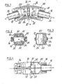
- the axial sections of the cable conduits are designated (16) in the figures.
- roller bends are installed in the cable conduit at points of critical changes of direction or curvatures.
- the roller bend consists of two half-shells (10) and (12), as a result of which it is not necessary to cut the drawing element-located in the cable conduit when installing the roller bend.
- the two half-shells are held together by screws (14).
- the entrance to and the exit from the roller bend are so designed as to be able to accept the ends (16) of the conduit which has been cut at the critical point, and form a Leak-tight seal with these by means of the gaskets (18).
- Guide rollers and support rollers (22) are arranged on spindles (24) within the interior space (20) of the roller bend.
- the spindles (24) are mounted in the recesses (26) and (28) which are present in the corresponding half-shells (10) and (12).
- the rollers (22) are in each case Located on the inside of the roller bend.
- a roller (30) running on a spindle (32) is attached within each half-shell and is aligned perpendicularly to the spindles (24) of the roLLers (22).
- the cable (34) will thus unroll on the rollers (22) and be additionally guided by the rollers (30), depending on the bend in each case.
- the gasket (36) Lying in the grooves (38) of each half-shell ensures the sealing-off of the interior space (20) of the roller bend.
- projections (40) and fixed centring elements (42) may also be provided in the interior space (20) to provide improved and error-free guiding of the cable to be drawn through the roller bend.
- the construction material of the roller bend may be metallic. More advantageously, it is made from corrosion-free, synthetic material.
- the degree of deflection of the roller bend can be designed for any change of direction by the cable conduit.
Landscapes
- Physics & Mathematics (AREA)
- General Physics & Mathematics (AREA)
- Optics & Photonics (AREA)
- Electric Cable Installation (AREA)
- Manufacturing Of Electric Cables (AREA)
- Communication Cables (AREA)
- Manufacturing Of Electrical Connectors (AREA)
- Ropes Or Cables (AREA)
- Confectionery (AREA)
- Detergent Compositions (AREA)
- Seasonings (AREA)
Priority Applications (1)
| Application Number | Priority Date | Filing Date | Title |
|---|---|---|---|
| AT84870075T ATE37633T1 (de) | 1983-06-10 | 1984-06-08 | Verfahren fuer die erstellung eines zum einziehen von kabeln geeigneten kabelschutzrohrsystems. |
Applications Claiming Priority (2)
| Application Number | Priority Date | Filing Date | Title |
|---|---|---|---|
| BE0/210979A BE897023A (nl) | 1983-06-10 | 1983-06-10 | Verfahren fur die erstellung eines kabelschutzrohrsystemes geeignet zum einziehen von kabelin, |
| BE210979 | 1983-06-10 |
Publications (2)
| Publication Number | Publication Date |
|---|---|
| EP0129529A1 true EP0129529A1 (de) | 1984-12-27 |
| EP0129529B1 EP0129529B1 (de) | 1988-09-28 |
Family
ID=3843648
Family Applications (1)
| Application Number | Title | Priority Date | Filing Date |
|---|---|---|---|
| EP84870075A Expired EP0129529B1 (de) | 1983-06-10 | 1984-06-08 | Verfahren für die Erstellung eines zum Einziehen von Kabeln geeigneten Kabelschutzrohrsystems |
Country Status (12)
| Country | Link |
|---|---|
| US (1) | US4600176A (de) |
| EP (1) | EP0129529B1 (de) |
| JP (1) | JPS60501537A (de) |
| AT (1) | ATE37633T1 (de) |
| AU (1) | AU3015284A (de) |
| BE (1) | BE897023A (de) |
| CA (1) | CA1255482A (de) |
| DE (1) | DE3474385D1 (de) |
| DK (1) | DK51185A (de) |
| NO (1) | NO850366L (de) |
| WO (1) | WO1984004998A1 (de) |
| ZA (1) | ZA844394B (de) |
Cited By (2)
| Publication number | Priority date | Publication date | Assignee | Title |
|---|---|---|---|---|
| JPS6226784A (ja) * | 1985-07-25 | 1987-02-04 | チツソエンジニアリング株式会社 | 表皮電流発熱管 |
| CN111193082A (zh) * | 2019-12-24 | 2020-05-22 | 浙江盛世互联科技有限公司 | 无法兰波导的法兰连接结构 |
Families Citing this family (10)
| Publication number | Priority date | Publication date | Assignee | Title |
|---|---|---|---|---|
| GB2243027A (en) * | 1990-04-10 | 1991-10-16 | Lin Lieh Chao | Conduit elbow |
| US5700977A (en) * | 1996-07-09 | 1997-12-23 | Ford; Michael | Electrical conduit fixture |
| US6462446B2 (en) | 1999-12-27 | 2002-10-08 | General Electric Company | Resilient ring motor mounting assembly |
| US6926257B1 (en) | 2003-04-03 | 2005-08-09 | Samuel E. Alcantara | Rollable conduit device |
| US7419136B2 (en) * | 2005-12-30 | 2008-09-02 | Chris Martinez | Cable pulling device |
| CN102044852B (zh) * | 2010-02-01 | 2013-03-27 | 何平 | 护线套管接头 |
| US9941676B2 (en) * | 2013-01-07 | 2018-04-10 | Chris Martinez | Cable pulling device with positioning and holding plates |
| CN107706829B (zh) * | 2017-11-07 | 2023-08-18 | 湖南世优电气股份有限公司 | 一种智能布线机器人及布线方法 |
| CN114614404B (zh) * | 2022-03-17 | 2023-11-14 | 新昌县新明实业有限公司 | 一种山区地区用电的承修配电线路敷设施工装置 |
| CN115995773B (zh) * | 2023-03-22 | 2023-05-16 | 昆明东电科技有限公司 | 配网带电作业夹持导线装置 |
Citations (5)
| Publication number | Priority date | Publication date | Assignee | Title |
|---|---|---|---|---|
| US1514612A (en) * | 1922-09-21 | 1924-11-11 | Russell & Stoll Company | Conduit fitting |
| GB269720A (en) * | 1926-04-01 | 1927-04-28 | Callenders Cable & Const Co | Improvements in or relating to apparatus for drawing in electric cables |
| US3201090A (en) * | 1963-02-06 | 1965-08-17 | Jones Milton Earl | Elbow adapter for electrical conduit wire puller |
| US3441189A (en) * | 1967-07-17 | 1969-04-29 | Gen Bearing Co Inc | Conduit roller bearing |
| US3770233A (en) * | 1970-01-27 | 1973-11-06 | Elroy J Mc | Cable draw mechanism |
Family Cites Families (4)
| Publication number | Priority date | Publication date | Assignee | Title |
|---|---|---|---|---|
| US458855A (en) * | 1891-09-01 | Hawser-guide | ||
| US2286781A (en) * | 1939-09-18 | 1942-06-16 | Greenlee Bros & Co | Cable pulling device |
| US3306581A (en) * | 1965-10-21 | 1967-02-28 | Arizona Utility Equipment Sale | Cable pulling mechanism |
| US4228990A (en) * | 1978-10-26 | 1980-10-21 | Steve Horvath | Hydraulic sewer cleaning system |
-
1983
- 1983-06-10 BE BE0/210979A patent/BE897023A/nl not_active IP Right Cessation
-
1984
- 1984-06-08 AU AU30152/84A patent/AU3015284A/en not_active Abandoned
- 1984-06-08 WO PCT/BE1984/000014 patent/WO1984004998A1/fr not_active Ceased
- 1984-06-08 JP JP59502349A patent/JPS60501537A/ja active Pending
- 1984-06-08 EP EP84870075A patent/EP0129529B1/de not_active Expired
- 1984-06-08 AT AT84870075T patent/ATE37633T1/de not_active IP Right Cessation
- 1984-06-08 DE DE8484870075T patent/DE3474385D1/de not_active Expired
- 1984-06-08 CA CA000456249A patent/CA1255482A/en not_active Expired
- 1984-06-08 US US06/705,434 patent/US4600176A/en not_active Expired - Fee Related
- 1984-06-11 ZA ZA844394A patent/ZA844394B/xx unknown
-
1985
- 1985-01-30 NO NO850366A patent/NO850366L/no unknown
- 1985-02-05 DK DK51185A patent/DK51185A/da unknown
Patent Citations (5)
| Publication number | Priority date | Publication date | Assignee | Title |
|---|---|---|---|---|
| US1514612A (en) * | 1922-09-21 | 1924-11-11 | Russell & Stoll Company | Conduit fitting |
| GB269720A (en) * | 1926-04-01 | 1927-04-28 | Callenders Cable & Const Co | Improvements in or relating to apparatus for drawing in electric cables |
| US3201090A (en) * | 1963-02-06 | 1965-08-17 | Jones Milton Earl | Elbow adapter for electrical conduit wire puller |
| US3441189A (en) * | 1967-07-17 | 1969-04-29 | Gen Bearing Co Inc | Conduit roller bearing |
| US3770233A (en) * | 1970-01-27 | 1973-11-06 | Elroy J Mc | Cable draw mechanism |
Cited By (3)
| Publication number | Priority date | Publication date | Assignee | Title |
|---|---|---|---|---|
| JPS6226784A (ja) * | 1985-07-25 | 1987-02-04 | チツソエンジニアリング株式会社 | 表皮電流発熱管 |
| CN111193082A (zh) * | 2019-12-24 | 2020-05-22 | 浙江盛世互联科技有限公司 | 无法兰波导的法兰连接结构 |
| CN111193082B (zh) * | 2019-12-24 | 2021-08-13 | 浙江盛世互联科技有限公司 | 无法兰波导的法兰连接结构 |
Also Published As
| Publication number | Publication date |
|---|---|
| ATE37633T1 (de) | 1988-10-15 |
| WO1984004998A1 (fr) | 1984-12-20 |
| NO850366L (no) | 1985-01-30 |
| ZA844394B (en) | 1985-02-27 |
| DK51185D0 (da) | 1985-02-05 |
| DE3474385D1 (en) | 1988-11-03 |
| EP0129529B1 (de) | 1988-09-28 |
| CA1255482A (en) | 1989-06-13 |
| JPS60501537A (ja) | 1985-09-12 |
| AU3015284A (en) | 1985-01-04 |
| BE897023A (nl) | 1983-12-12 |
| US4600176A (en) | 1986-07-15 |
| DK51185A (da) | 1985-02-05 |
Similar Documents
| Publication | Publication Date | Title |
|---|---|---|
| EP0129529A1 (de) | Verfahren für die Erstellung eines zum Einziehen von Kabeln geeigneten Kabelschutzrohrsystems | |
| US5259418A (en) | Heat reshapeable regid conduit | |
| US6259843B1 (en) | Optical cable, a method of laying an optical cable, and a data transfer system using the optical cable | |
| EP0158416A1 (de) | Installation von Fernmeldekabeln in ein Rohr | |
| US4854665A (en) | Coupling for joining axial sections of duct for fiber optic cables | |
| HUP0201617A2 (en) | Multiple channel duct assembly for cables | |
| US5029815A (en) | Cable guide arrangement | |
| EP0410736A2 (de) | Installation von elektrischen Kabeln | |
| KR102584231B1 (ko) | 전력 케이블 중간 접속용 슬리브 부재 장착장치 | |
| JPH0618089B2 (ja) | ケ−ブル線路 | |
| JP3276934B2 (ja) | 地中埋設管路構造及びその保護管並びにその管路へのケーブル通線方法 | |
| JPH0738885Y2 (ja) | 光フアイバケ−ブル布設用管路 | |
| ES293412U (es) | Metodo para la produccion de un sistema de conduccion de cables adecuado para el tendido de cables | |
| JPH05328568A (ja) | フロアダクト型配線ケーブル | |
| JP2935424B1 (ja) | ケーブル保護管 | |
| CN114725857A (zh) | 一种卡扣塑料管 | |
| RU2666813C2 (ru) | Волоконно-оптическая линия связи | |
| JPH0479713A (ja) | 埋設管内へのケーブル敷設方法 | |
| RS52113B (sr) | Cev | |
| FR2451533A1 (fr) | Tube flexible | |
| JP2000291828A (ja) | 管路構造 | |
| Medek et al. | CABLE INSTALLATION | |
| JP2000039543A (ja) | 通線用パイプの接続構造 | |
| Thue | Cable Installation | |
| JPS6212316A (ja) | 電力ケ−ブルの管路布設方法 |
Legal Events
| Date | Code | Title | Description |
|---|---|---|---|
| PUAI | Public reference made under article 153(3) epc to a published international application that has entered the european phase |
Free format text: ORIGINAL CODE: 0009012 |
|
| AK | Designated contracting states |
Designated state(s): AT CH DE FR GB IT LI LU NL SE |
|
| ITCL | It: translation for ep claims filed |
Representative=s name: BARZANO' E ZANARDO ROMA S.P.A. |
|
| 17P | Request for examination filed |
Effective date: 19850320 |
|
| 17Q | First examination report despatched |
Effective date: 19860418 |
|
| RAP1 | Party data changed (applicant data changed or rights of an application transferred) |
Owner name: KABELWERK EUPEN AG CABLERIE D'EUPEN SA KABELFABRIE |
|
| ITF | It: translation for a ep patent filed | ||
| GRAA | (expected) grant |
Free format text: ORIGINAL CODE: 0009210 |
|
| AK | Designated contracting states |
Kind code of ref document: B1 Designated state(s): AT CH DE FR GB IT LI LU NL SE |
|
| REF | Corresponds to: |
Ref document number: 37633 Country of ref document: AT Date of ref document: 19881015 Kind code of ref document: T |
|
| REF | Corresponds to: |
Ref document number: 3474385 Country of ref document: DE Date of ref document: 19881103 |
|
| ET | Fr: translation filed | ||
| PG25 | Lapsed in a contracting state [announced via postgrant information from national office to epo] |
Ref country code: GB Effective date: 19890608 Ref country code: AT Effective date: 19890608 |
|
| PG25 | Lapsed in a contracting state [announced via postgrant information from national office to epo] |
Ref country code: SE Effective date: 19890609 |
|
| PG25 | Lapsed in a contracting state [announced via postgrant information from national office to epo] |
Ref country code: LU Free format text: LAPSE BECAUSE OF NON-PAYMENT OF DUE FEES Effective date: 19890630 Ref country code: LI Effective date: 19890630 Ref country code: CH Effective date: 19890630 |
|
| PLBE | No opposition filed within time limit |
Free format text: ORIGINAL CODE: 0009261 |
|
| STAA | Information on the status of an ep patent application or granted ep patent |
Free format text: STATUS: NO OPPOSITION FILED WITHIN TIME LIMIT |
|
| 26N | No opposition filed | ||
| GBPC | Gb: european patent ceased through non-payment of renewal fee | ||
| PG25 | Lapsed in a contracting state [announced via postgrant information from national office to epo] |
Ref country code: FR Free format text: LAPSE BECAUSE OF NON-PAYMENT OF DUE FEES Effective date: 19900228 |
|
| REG | Reference to a national code |
Ref country code: CH Ref legal event code: PL |
|
| REG | Reference to a national code |
Ref country code: FR Ref legal event code: ST |
|
| EUG | Se: european patent has lapsed |
Ref document number: 84870075.3 Effective date: 19900418 |
|
| PGFP | Annual fee paid to national office [announced via postgrant information from national office to epo] |
Ref country code: NL Payment date: 19950627 Year of fee payment: 12 |
|
| PGFP | Annual fee paid to national office [announced via postgrant information from national office to epo] |
Ref country code: DE Payment date: 19950823 Year of fee payment: 12 |
|
| PG25 | Lapsed in a contracting state [announced via postgrant information from national office to epo] |
Ref country code: NL Effective date: 19970101 |
|
| PG25 | Lapsed in a contracting state [announced via postgrant information from national office to epo] |
Ref country code: DE Effective date: 19970301 |
|
| NLV4 | Nl: lapsed or anulled due to non-payment of the annual fee |
Effective date: 19970101 |