EP0129566B1 - Ultraschallverfahren zum messen von spannungen in dazu geeigneten bolzen oder dgl. - Google Patents
Ultraschallverfahren zum messen von spannungen in dazu geeigneten bolzen oder dgl. Download PDFInfo
- Publication number
- EP0129566B1 EP0129566B1 EP84900015A EP84900015A EP0129566B1 EP 0129566 B1 EP0129566 B1 EP 0129566B1 EP 84900015 A EP84900015 A EP 84900015A EP 84900015 A EP84900015 A EP 84900015A EP 0129566 B1 EP0129566 B1 EP 0129566B1
- Authority
- EP
- European Patent Office
- Prior art keywords
- reflectors
- acoustic
- bolt
- measurement
- stress
- Prior art date
- Legal status (The legal status is an assumption and is not a legal conclusion. Google has not performed a legal analysis and makes no representation as to the accuracy of the status listed.)
- Expired
Links
- 238000000034 method Methods 0.000 title claims abstract description 45
- 238000005259 measurement Methods 0.000 claims abstract description 54
- 238000002592 echocardiography Methods 0.000 claims abstract 4
- 230000035882 stress Effects 0.000 claims description 56
- 230000008569 process Effects 0.000 claims description 20
- 239000000463 material Substances 0.000 claims description 15
- 230000006355 external stress Effects 0.000 claims description 3
- 230000005540 biological transmission Effects 0.000 claims description 2
- 239000000523 sample Substances 0.000 description 31
- 239000002964 rayon Substances 0.000 description 15
- 229920000297 Rayon Polymers 0.000 description 14
- 241001644893 Entandrophragma utile Species 0.000 description 10
- 238000005452 bending Methods 0.000 description 10
- 238000010168 coupling process Methods 0.000 description 7
- 238000005859 coupling reaction Methods 0.000 description 7
- 229920003023 plastic Polymers 0.000 description 7
- 239000004033 plastic Substances 0.000 description 7
- 230000008878 coupling Effects 0.000 description 6
- 229910000831 Steel Inorganic materials 0.000 description 5
- 230000000694 effects Effects 0.000 description 5
- 239000007788 liquid Substances 0.000 description 5
- 244000045947 parasite Species 0.000 description 5
- 239000010959 steel Substances 0.000 description 5
- 238000002604 ultrasonography Methods 0.000 description 5
- 230000007797 corrosion Effects 0.000 description 4
- 238000005260 corrosion Methods 0.000 description 4
- 230000003071 parasitic effect Effects 0.000 description 4
- VVQNEPGJFQJSBK-UHFFFAOYSA-N Methyl methacrylate Chemical compound COC(=O)C(C)=C VVQNEPGJFQJSBK-UHFFFAOYSA-N 0.000 description 3
- 229920005372 Plexiglas® Polymers 0.000 description 3
- 230000008901 benefit Effects 0.000 description 3
- 239000013078 crystal Substances 0.000 description 3
- 230000007935 neutral effect Effects 0.000 description 3
- 230000006835 compression Effects 0.000 description 2
- 238000007906 compression Methods 0.000 description 2
- 239000008710 crystal-8 Substances 0.000 description 2
- 235000021183 entrée Nutrition 0.000 description 2
- 238000000691 measurement method Methods 0.000 description 2
- 230000036316 preload Effects 0.000 description 2
- 239000007787 solid Substances 0.000 description 2
- 230000009897 systematic effect Effects 0.000 description 2
- 235000019687 Lamb Nutrition 0.000 description 1
- 230000002745 absorbent Effects 0.000 description 1
- 239000002250 absorbent Substances 0.000 description 1
- 238000013459 approach Methods 0.000 description 1
- 238000011088 calibration curve Methods 0.000 description 1
- 230000008859 change Effects 0.000 description 1
- 238000010276 construction Methods 0.000 description 1
- 238000012937 correction Methods 0.000 description 1
- 230000001419 dependent effect Effects 0.000 description 1
- 238000001514 detection method Methods 0.000 description 1
- 238000009826 distribution Methods 0.000 description 1
- 230000005284 excitation Effects 0.000 description 1
- 239000003302 ferromagnetic material Substances 0.000 description 1
- 239000000835 fiber Substances 0.000 description 1
- 238000002955 isolation Methods 0.000 description 1
- 238000005304 joining Methods 0.000 description 1
- 230000033001 locomotion Effects 0.000 description 1
- 238000011326 mechanical measurement Methods 0.000 description 1
- 230000035515 penetration Effects 0.000 description 1
- 230000001603 reducing effect Effects 0.000 description 1
- 230000009467 reduction Effects 0.000 description 1
- 230000002829 reductive effect Effects 0.000 description 1
- 230000002787 reinforcement Effects 0.000 description 1
- 230000000717 retained effect Effects 0.000 description 1
- 230000002441 reversible effect Effects 0.000 description 1
- 230000002459 sustained effect Effects 0.000 description 1
- 238000012360 testing method Methods 0.000 description 1
- 230000007704 transition Effects 0.000 description 1
Images

Classifications
-
- G—PHYSICS
- G01—MEASURING; TESTING
- G01L—MEASURING FORCE, STRESS, TORQUE, WORK, MECHANICAL POWER, MECHANICAL EFFICIENCY, OR FLUID PRESSURE
- G01L5/00—Apparatus for, or methods of, measuring force, work, mechanical power, or torque, specially adapted for specific purposes
- G01L5/24—Apparatus for, or methods of, measuring force, work, mechanical power, or torque, specially adapted for specific purposes for determining value of torque or twisting moment for tightening a nut or other member which is similarly stressed
- G01L5/246—Apparatus for, or methods of, measuring force, work, mechanical power, or torque, specially adapted for specific purposes for determining value of torque or twisting moment for tightening a nut or other member which is similarly stressed using acoustic waves
-
- F—MECHANICAL ENGINEERING; LIGHTING; HEATING; WEAPONS; BLASTING
- F16—ENGINEERING ELEMENTS AND UNITS; GENERAL MEASURES FOR PRODUCING AND MAINTAINING EFFECTIVE FUNCTIONING OF MACHINES OR INSTALLATIONS; THERMAL INSULATION IN GENERAL
- F16B—DEVICES FOR FASTENING OR SECURING CONSTRUCTIONAL ELEMENTS OR MACHINE PARTS TOGETHER, e.g. NAILS, BOLTS, CIRCLIPS, CLAMPS, CLIPS OR WEDGES; JOINTS OR JOINTING
- F16B31/00—Screwed connections specially modified in view of tensile load; Break-bolts
- F16B31/02—Screwed connections specially modified in view of tensile load; Break-bolts for indicating the attainment of a particular tensile load or limiting tensile load
- F16B2031/022—Screwed connections specially modified in view of tensile load; Break-bolts for indicating the attainment of a particular tensile load or limiting tensile load using an ultrasonic transducer
-
- G—PHYSICS
- G01—MEASURING; TESTING
- G01N—INVESTIGATING OR ANALYSING MATERIALS BY DETERMINING THEIR CHEMICAL OR PHYSICAL PROPERTIES
- G01N2291/00—Indexing codes associated with group G01N29/00
- G01N2291/02—Indexing codes associated with the analysed material
- G01N2291/028—Material parameters
- G01N2291/02827—Elastic parameters, strength or force
Definitions
- the present invention relates to a method for measuring the stress in a bolt or the like, in particular a high-strength bolt, a threaded rod or a tie rod, by reflection of acoustic waves.
- It also relates to bolts or the like adapted so as to be able to measure the stress by means of the method according to the invention.
- constraint should be understood to mean the cause which causes the transit time of the useful acoustic ray to vary over a route of determined length.
- the invention finds in particular applications in the measurement of the stress appearing in bolts, threaded rods and tie rods, but is not limited to these applications.
- high-strength bolts are subjected to a prestressing state during assembly so as to develop local pressure on the contact surfaces of the assembled elements capable of opposing their relative movement under the effect of external stresses.
- the propagation speeds of acoustic waves and in particular of longitudinal waves (L waves), transverse waves (T waves) and surface waves (R waves) are a function of the physical parameters of the material environment in which propagates the wave.
- L waves longitudinal waves
- T waves transverse waves
- R waves surface waves
- the speeds of the L waves, T waves and R waves are a function of the longitudinal modulus of elasticity E, the density p and the Poisson's ratio ⁇ .
- Lamb waves their propagation speed is also a function of frequency.
- the wave velocities are influenced by all the factors which influence these physical parameters and in particular by the stress and by the temperature.
- the longitudinal and transverse acoustic waves emitted by a plane crystal have, for frequencies depending on the material medium and the equivalent diameter of the emitting crystal, a directivity property which makes it possible to selectively locate anomalies reflecting all or part of the energy of the incident wave, and this as a function of the respective positions of the transmitter as well as of the receiver and of the angle of penetration of the axis of the beam into the material.
- the stress is measured either by measuring the transit time of an ultrasonic wave in the length of the body, for example of the bolt, a measurement which can be carried out by an ultrasound pulse method, or by determining the frequencies of resonance of a sustained wave.
- the resonant frequencies constitute an arithmetic progression whose reason is the fundamental frequency.
- the inverse of the latter is the minimum transit time of the useful acoustic ray.
- a measurement by transmission can be carried out by placing an ultrasonic transmitter on one side of the room and a receiver on the opposite side. It is however also possible to carry out a measurement by reflection using one or two probes which consist of a transmitter and a receiver, most often combined or separated in the same probe, the measurement then being carried out by detection of echoes resulting from reflections of the wave on the ends of the part and determination of the transit time of the useful acoustic ray, by determination of the time separating the appearance of the feet from the echo peaks of ends on the representation of type A, each reflection causing, if the reflected energy returns to the receiver, an echo of anomaly characterized by a peak in the type A representation used in conventional conventional ultrasonic testing devices.
- the classic way to determine the stress in a bolt is to adequately place a probe on one end of the bolt and measure the time required for the useful acoustic radius to travel two or a multiple of twice the length of the bolt , the acoustic ray being partially or totally reflected at the two ends of the bolt.
- the transit time in the bolt is a function of the stress on the path of the useful acoustic radius because this influences the speed of transit and the length of transit.
- the present invention therefore aims to provide a method for measuring the stress in a bolt or similar parts by taking advantage of the reflection of an acoustic ray and by measuring the transit time thereof using an apparatus. ad-hoc for example an apparatus determining the time between the feet of two characteristic echo reflection peaks while eliminating the drawbacks of known methods or reducing their impact to a greater or lesser extent.
- the method of the present invention is characterized in that one chooses in the bolt or similar part one or more ends of rectilinear measurement paths materialized by an internal artificial reflector, in that one sends a beam of acoustic waves of in such a way that acoustic rays carrying sufficient energy touch the useful reflectors, in that the echoes corresponding to the reflectors are selected, in that the transit times characteristic of the useful acoustic rays are determined by measurement to the artificial reflector internal and in that one transposes the transit times for each internal reflector considered in isolation or the respective differences in transit time of each pair of reflectors in value of external stress or in value of stress in the zone delimited by each pair of reflectors .
- a preferred practical embodiment of the invention is characterized in that one chooses in the medium a rectilinear measurement path limited by two internal artificial reflectors, in that one sends a beam of acoustic waves whose axis is substantially coincident with the rectilinear measurement path chosen, in that the echoes corresponding to the reflectors are selected, in that the transit time characteristic of an acoustic ray between the two reflectors is measured, which is the difference in transit times acoustic rays, coincident or substantially parallel to each of the two reflectors and in that the transit time values are transposed into stress values.
- the characteristic transit time is the minimum transit time.
- an apparatus will advantageously be used making it possible to select the feet of peaks due to the internal artificial reflectors and to differentiate between the two transit times of the wave from the emitting source to the corresponding reflector.
- the artificial reflectors are advantageously arranged in such a way that the path of the acoustic wave is parallel to and very close to the neutral line, or even on the latter. This arrangement makes it possible to practically eliminate the influences of bending which can distort the measurements in the current process.
- the beam used will be focused.
- the transit time can be measured by continuous emission and determination of the resonance frequencies of the wave due to the internal reflectors.
- the resonant frequencies constitute an arithmetic progression whose reason is the fundamental frequency.
- the inverse of the latter is the minimum transit time of the useful acoustic ray between the reflectors concerned.
- the measurement of the transit time of the acoustic wave between the two reflectors will advantageously be carried out by the use of a thickness meter exploiting the ultrasonic waves.
- the ultrasonic thickness measuring device can be considered as a device which directly or indirectly measures a transit time of an ultrasonic beam in the workpiece.
- the transit time t of the acoustic wave between the two internal reflectors will be measured when the body is subjected to a stress.
- transverse ultrasonic waves could be used in case the stress applied to the body during the calibration phase shows an influence on the transit time characteristic of the useful acoustic ray along the line separating the artificial internal reflectors .
- This however has several drawbacks known to those skilled in the art, in particular the difficulty of generating this type of wave in the material in the case of normal propagation at the end of the part.
- any type of acoustic wave could be used, in particular surface ultrasonic waves, provided that the stress applied to the body has an influence on the transit time characteristic of the useful acoustic ray following the stress thus created on the line separating the internal artificial reflectors.
- the internal artificial reflectors should be relatively close to the surface since the surface wave only affects a depth of the material on the order of the wavelength.
- longitudinal ultrasonic waves are used which have the advantage, in the event of normal incidence, of being easily transmitted to the part.
- a longitudinal wave and a transverse wave could also be used in combination and concomitantly or successively, which gives additional data for determining the stress.
- the ratio of the respective transit times of an L wave and a T wave in a sufficiently homogeneous and isotropic medium between two reflectors is equal to the inverse of the ratio of the respective speeds of these two waves and is only dependent on the Poisson's ratio value ⁇ . It therefore does not depend on the distance between the reflectors. It is therefore sufficient to calibrate this ratio of transit times for the material as a function of the stress. It is desirable to do this on the component with the reflectors.
- the method of the invention therefore no longer requires calibration for each position of the nut in the case of application to a bolted structure.
- An equivalent remark can be made in the case of the threaded rod and the threaded tie rod or anchored in a solid block.
- the effect of bending on the measurement is considerably reduced compared to known methods.
- the reflectors are smaller and the wave path is that connecting by a straight line the two reflectors arranged on the slightly curved neutral line.
- the error due to the difference between the length of the rope and the length of the arc formed by the neutral fiber is not appreciably modified but the useful acoustic radius propagates in a medium close to the axis of the part where the disturbing stress due to bending can usually be considered negligible while in known methods, this radius is displaced in the compression zone introduced by bending.
- the probe will advantageously always be in the same place on the head, otherwise we will not receive a signal or we will receive signals of different energy.
- This positioning is made possible by the presence of artificial internal reflectors.
- it will possibly require the use of a conventional device making it possible to display the amplitude of the peaks of the reflection echoes relating to the internal artificial reflectors in a type A or equivalent representation so as to position the probe at the location where the peaks reflection echoes of the two artificial reflectors if possible respectively identical in amplitude to the peaks obtained during the calibration.
- the transmitted acoustic energy depends inter alia on the thickness of the coupling liquid and on the pressure exerted on the probe, it is at least necessary that the relative heights of the peaks are substantially in the same ratio as during the calibration, which means that the proportions of the energy transmitted in the bolt and reflected by each reflector to the receiver are substantially identical.
- the peaks of the reflection echoes of the two artificial reflectors will be as much as possible simultaneously maximum when the beam axis is substantially coincident with the axis of the bolt.
- the reflectors are bores orthogonal to the barrel of the bolt and making between them a certain angle, it is the reflection by the second reflector on either side of the shadow created by the first.
- the presence of internal reflectors no longer requires generating and receiving the acoustic wave by contact.
- the field of application is not limited to steel.
- the artificial reflectors consist of perforations or transverse bores. These are advantageously arranged in parallel planes at an angle to each other. Preferably the two reflectors are perpendicular to each other. It may be advantageous, in the case of parts subjected to torsion, to arrange the perforations or bores at an angle between 0 ° and 90 ° and in a direction such that this angle increases with the angular deformation of torsion.
- the reflectors consist of two coaxial bores of small diameter, but of different diameter and of different depth, the difference in depth determining the exploited area of transit of the useful acoustic ray.
- the transition zone between the two bores has a sharp edge and a flat connection surface, perpendicular to the axis. It is advantageous for the acoustic wave to enter the part through the end opposite the bore. It is certainly possible to find other possibilities for reflectors and the invention is not limited to the cited cases of application, nor to the particular embodiment indicated of reflectors.
- the present invention also relates to parts characterized in that they include artificial reflectors.
- assembly elements for example, high-strength bolts, threaded rods, smooth or ribbed, rivets, studs or even structural elements, in particular beams or other construction elements.
- These parts are advantageously provided with a means for geometrical positioning of the probe on the contact face, in particular a positioning sleeve or a housing in the end of the part.
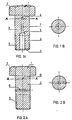
- FIG. 1 shows by way of example, a high-strength bolt 1 comprising a head 2 and a body 3 provided at its end 4 opposite the head, with a thread 5. From the end 4 of the bolt 1 , two coaxial bores 6, 7 of different diameter were machined.
- the bore 6 advantageously has a diameter greater than that of the bore 7 so as not to be masked by the "shadow" formed by the first reflector 8 formed by the bottom of the bore 7, when the probe placed on head 2 sends an ultrasonic wave through the bolt.
- the second artificial reflector is created by the shoulder 9.
- the bores are advantageously arranged on the axial line of the bolt.
- the reflectors 8 and 9 can be placed in such a way that the measurement zone is arranged only in the chosen stress zone.
- the part of the body of the bolt between the bearing surface of the head and the thread engaged in the nut is the zone in which the stress is significant.
- an apparatus intended for thickness measurements by ultrasound of the UTG 5A-IIB-SONATEST type was used which automatically calculates the difference in appearance of the peak feet of the two echoes resulting from the reflection of the useful acoustic ray on the two. artificial reflectors, by eliminating the other echoes in particular the beginning and background echo of parts and if necessary the parasitic echoes of the part beyond the second artificial reflector for example those resulting from edges and inclined surfaces of the nets .
- Figure 2 shows another way of making artificial reflectors.
- Two transverse holes were drilled in the body 3 of the bolt 1, perpendicular to the axis of the latter.
- the holes 10, 11 are advantageously in parallel planes while forming an angle relative to each other in projection on one of the planes so as to intersect by example on the axial line.
- the two perforations 10, 11 are advantageously perpendicular to each other.
- the ultrasonic waves will be reflected by the bottom of the bore 7 and by the wall of the bore 11.
- the reflectors can be positioned so that the transit time of the disturbing echoes of the nets is greater than the transit time of the useful acoustic ray reflected on the most distant artificial reflector. In this way, they are not troublesome for the measurement in the first course of the wave.
- the measurement of the temperature could be done concomitantly with the measurement of the stress by adequately embedding a temperature sensor, such as for example a thermocouple in the probe.
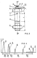
- FIG. 3 represents a bolt provided with two internal artificial reflectors in this case transverse bores 1 and 2 diametrical in two parallel planes perpendicular to the axis of the bolt.
- the bolt is provided with a nut 3.
- a probe 5 emitting and receiving ultrasound has been placed which contains a piezoelectric crystal 8, a plexiglass delay line 7, an absorbent material 6.
- the length of the path in the plexiglass is p, in the coupling liquid e, in the bolt to the first reflector 1, between the two reflectors L, between the second reflector and the end 1 2 .
- the bolt is subjected to a force F which varies the transit time characteristic of the useful acoustic radius between the two reflectors.
- the peak 3 is linked to the excitation of the crystal 8 of FIG. 3.
- Peak 4 relates to the reflection at the plexiglass-coupling liquid interface.
- Peak 5 relates to the reflection at the liquid coupling-steel interface.
- the peak 6 relates to the reflection on the reflector 1 in FIG. 3.
- the peak 7 relates to the reflection on the reflector 2 in FIG. 3.
- the peaks 8 relate to the reflections on the faces and edges of the thread.
- the peak 9 relates to the reflection on the end of the bolt.
- Cp is the speed of the ultrasonic wave in the plexiglass.
- C a is the speed of the ultrasonic order in steel.
- Each configuration of the connecting element corresponds to a straight line.
Landscapes
- Physics & Mathematics (AREA)
- Acoustics & Sound (AREA)
- General Physics & Mathematics (AREA)
- Force Measurement Appropriate To Specific Purposes (AREA)
- Investigating Or Analyzing Materials By The Use Of Ultrasonic Waves (AREA)
- Length Measuring Devices Characterised By Use Of Acoustic Means (AREA)
Claims (22)
Priority Applications (1)
| Application Number | Priority Date | Filing Date | Title |
|---|---|---|---|
| AT84900015T ATE34463T1 (de) | 1982-12-24 | 1983-12-20 | Ultraschallverfahren zum messen von spannungen in dazu geeigneten bolzen oder dgl. |
Applications Claiming Priority (2)
| Application Number | Priority Date | Filing Date | Title |
|---|---|---|---|
| LU84553A LU84553A1 (fr) | 1982-12-24 | 1982-12-24 | Procede de mesure de contrainte dans un milieu et element et assemblage pour la mise en oeuvre de ce procede |
| LU84553 | 1982-12-24 |
Publications (2)
| Publication Number | Publication Date |
|---|---|
| EP0129566A1 EP0129566A1 (de) | 1985-01-02 |
| EP0129566B1 true EP0129566B1 (de) | 1988-05-18 |
Family
ID=19730004
Family Applications (2)
| Application Number | Title | Priority Date | Filing Date |
|---|---|---|---|
| EP84900015A Expired EP0129566B1 (de) | 1982-12-24 | 1983-12-20 | Ultraschallverfahren zum messen von spannungen in dazu geeigneten bolzen oder dgl. |
| EP83870137A Pending EP0117387A1 (de) | 1982-12-24 | 1983-12-20 | Verfahren zum Messen von Spannungen in Bolzen oder dgl. mittels Ultraschall und dazu geeignetes Stück |
Family Applications After (1)
| Application Number | Title | Priority Date | Filing Date |
|---|---|---|---|
| EP83870137A Pending EP0117387A1 (de) | 1982-12-24 | 1983-12-20 | Verfahren zum Messen von Spannungen in Bolzen oder dgl. mittels Ultraschall und dazu geeignetes Stück |
Country Status (8)
| Country | Link |
|---|---|
| US (1) | US4569229A (de) |
| EP (2) | EP0129566B1 (de) |
| JP (1) | JPS60500461A (de) |
| AT (1) | ATE34463T1 (de) |
| DE (1) | DE3376679D1 (de) |
| LU (1) | LU84553A1 (de) |
| OA (1) | OA07799A (de) |
| WO (1) | WO1984002577A1 (de) |
Families Citing this family (48)
| Publication number | Priority date | Publication date | Assignee | Title |
|---|---|---|---|---|
| US4846001A (en) * | 1987-09-11 | 1989-07-11 | Sps Technologies, Inc. | Ultrasonic load indicating member |
| US4899591A (en) * | 1987-09-11 | 1990-02-13 | Sps Technologies, Inc. | Ultrasonic load indicating member, apparatus and method |
| US5161594A (en) * | 1988-12-21 | 1992-11-10 | Raymond Engineering Inc. | Tie bar monitoring system |
| US5029480A (en) * | 1990-02-05 | 1991-07-09 | Sps Technologies, Inc. | Ultrasonic load indicating member |
| US5220839A (en) * | 1990-08-27 | 1993-06-22 | Ultrafast, Inc. | Ultrasonic load measuring device with control feature |
| US5131276A (en) * | 1990-08-27 | 1992-07-21 | Ultrafast, Inc. | Ultrasonic load indicating member with transducer |
| US5205176A (en) * | 1990-08-27 | 1993-04-27 | Ultrafast, Inc. | Ultrasonic load cell with transducer |
| US5343785A (en) * | 1991-10-23 | 1994-09-06 | Emerson Electric Co. | Ultrasonic bolting control apparatus |
| US5807048A (en) * | 1992-09-03 | 1998-09-15 | European Atomic Energy Community (Euratom) | Sealing fastener with ultrasonic identifier and removal attempt indicator, and ultrasonic reading device for same |
| JP2856043B2 (ja) * | 1993-09-28 | 1999-02-10 | 株式会社日立製作所 | 応力評価方法およびその装置 |
| AU3203797A (en) * | 1996-05-03 | 1997-11-26 | Ultrafast, Inc. | A technique for eliminating ambiguity when making pulse-echo timing measurments |
| US6009759A (en) * | 1996-05-03 | 2000-01-04 | Ultrafast, Inc. | Minimizing the effect of bending on ultrasonic measurements in a load-bearing member |
| AU758290B2 (en) * | 1996-05-03 | 2003-03-20 | Ald Vacuum Technologies Ag | Minimizing the effect of bending on ultrasonic measurements in a load-bearing member |
| AU737072B2 (en) * | 1996-05-03 | 2001-08-09 | Ald Vacuum Technologies Ag | Minimizing the effect of bending on ultrasonic measurements in a load-bearing member |
| FR2750498B1 (fr) * | 1996-07-01 | 1998-09-04 | Freyssinet Int Stup | Procede pour mesurer par ultrasons la tension residuelle d'une barre de precontrainte metallique |
| DE19643933C1 (de) * | 1996-10-30 | 1998-03-12 | Thomas Dipl Ing Loeffler | Verfahren zur Herstellung von Schraubverbindungen |
| WO1998035791A1 (de) * | 1997-02-12 | 1998-08-20 | Loeffler Thomas | Verfahren und vorrichtung zum herstellen von schraubverbindungen |
| GB2345755A (en) * | 1999-01-13 | 2000-07-19 | Solartron Group Ltd | Method and apparatus for torque measurement |
| NL1011591C1 (nl) * | 1999-03-18 | 2000-10-03 | Konink Nedschroef Holding N V | Schroefbout met meetvlakken. |
| US8033181B2 (en) * | 2001-01-29 | 2011-10-11 | Innovation Plus, Llc | Probe for fastener identification and ultrasonic load measurement |
| EP1364132B2 (de) * | 2001-01-29 | 2023-09-13 | Innovation Plus, L.L.C. | Lastanzeigeglied mit identifizierungsmarkierung |
| US7467556B2 (en) * | 2001-01-29 | 2008-12-23 | Innovation Plus, Llc | Thread forming fasteners for ultrasonic load measurement and control |
| US6748808B2 (en) | 2001-08-14 | 2004-06-15 | Varco I/P, Inc. | Flaw detection in tubular members |
| US6622561B2 (en) | 2001-08-14 | 2003-09-23 | Varco I/P, Inc. | Tubular member flaw detection |
| US6578422B2 (en) | 2001-08-14 | 2003-06-17 | Varco I/P, Inc. | Ultrasonic detection of flaws in tubular members |
| US6745136B2 (en) | 2002-07-02 | 2004-06-01 | Varco I/P, Inc. | Pipe inspection systems and methods |
| US6782751B2 (en) * | 2002-09-13 | 2004-08-31 | Ctes, L.C. | Pipe inspection systems and methods |
| AU2003275012A1 (en) * | 2002-09-19 | 2004-04-08 | Innovation Plus, L.L.C. | Thread forming fasteners for ultrasonic load measurement and control |
| IL160364A0 (en) * | 2003-12-30 | 2009-02-11 | Nexense Ltd | Method and apparatus for measuring torque and other forces |
| IL159651A0 (en) * | 2003-12-30 | 2004-06-01 | Nexense Ltd | Method and apparatus for measuring torque |
| JP4524197B2 (ja) * | 2004-03-02 | 2010-08-11 | 株式会社サンノハシ | 軸力検知締結工具、ボルト、ボルトの製造方法 |
| FR2919050B1 (fr) * | 2007-07-20 | 2012-03-23 | Centre Nat Rech Scient | Jauge de contrainte de type structure resonante acoustique et capteur d'au moins un parametre physique utilisant une telle jauge de contrainte. |
| US7994901B2 (en) * | 2008-02-18 | 2011-08-09 | Tag Blue L.L.C. | Lug stud and lug nut monitoring system, method, and components therefor |
| GB0815038D0 (en) * | 2008-08-18 | 2008-09-24 | Seaman Peter | Improvements in or relating to analysing structual memebers |
| US20100161246A1 (en) * | 2008-12-19 | 2010-06-24 | Caterpillar Inc. | Fault detection system and method |
| US9339926B2 (en) | 2010-05-03 | 2016-05-17 | Innovation Plus, Llc | System for performing predefined fastener installation procedures |
| US9016997B2 (en) | 2011-10-11 | 2015-04-28 | Safety Trim Worldwide Holdings, Ltd. | Sensing safety devices |
| AU2011235942B2 (en) * | 2011-10-11 | 2015-01-22 | Nicholas Charles Dooner | Safetytrim nut locking device |
| DE102012005614B4 (de) * | 2012-03-22 | 2013-10-17 | Matthias Brenneis | Sensorisches Verbindungselement und Herstellverfahren |
| FR2999708B1 (fr) * | 2012-12-18 | 2014-12-05 | Vallourec Mannesmann Oil & Gas | Procede de controle d'un etat de vissage d'un joint filete tubulaire |
| TWI518253B (zh) * | 2013-03-12 | 2016-01-21 | Kabo Tool Co | Can feel the tension of the screw pieces |
| US9632016B2 (en) * | 2013-05-20 | 2017-04-25 | The Boeing Company | Material strain measurement method by means of laser ablation |
| JP6823625B2 (ja) * | 2018-08-03 | 2021-02-03 | 本田技研工業株式会社 | 締付装置 |
| US10724857B1 (en) * | 2018-11-09 | 2020-07-28 | Smart Wires Inc. | Real-time bolt monitoring system |
| GB2593743A (en) * | 2020-03-31 | 2021-10-06 | Tribosonics Ltd | Bolt transducer |
| CN112179553B (zh) * | 2020-09-09 | 2021-06-22 | 西南交通大学 | 一种超声同步测量螺栓轴向力和剪切力的方法 |
| CN111998983B (zh) * | 2020-09-12 | 2025-05-16 | 眉山中车紧固件科技有限公司 | 一种用于超声波预紧力检测的环槽铆钉及在役检测方法 |
| CN113865762A (zh) * | 2021-10-08 | 2021-12-31 | 上海天乘实业有限公司 | 拉铆钉轴力超声波测试装置及其测试方法 |
Family Cites Families (5)
| Publication number | Priority date | Publication date | Assignee | Title |
|---|---|---|---|---|
| US3538750A (en) * | 1968-04-26 | 1970-11-10 | Panametrics | High temperature ultrasonic measuring system |
| US3636754A (en) * | 1970-07-16 | 1972-01-25 | Parametrics Inc | Ultrasonic profile measuring apparatus |
| GB1369858A (en) * | 1971-11-12 | 1974-10-09 | Toyota Motor Co Ltd | Ultrasonic methods of measuring axial force |
| US3969960A (en) * | 1974-05-13 | 1976-07-20 | Dominick A Pagano | Method and apparatus for tightening a bolt to exert a predetermined tension force by monitoring bolt elongation while the bolt is being installed |
| US4014208A (en) * | 1976-04-01 | 1977-03-29 | Rockwell International Corporation | Ultrasonic system for measuring dimensional or stress change in structural member |
-
1982
- 1982-12-24 LU LU84553A patent/LU84553A1/fr unknown
-
1983
- 1983-12-20 EP EP84900015A patent/EP0129566B1/de not_active Expired
- 1983-12-20 EP EP83870137A patent/EP0117387A1/de active Pending
- 1983-12-20 AT AT84900015T patent/ATE34463T1/de not_active IP Right Cessation
- 1983-12-20 DE DE8484900015T patent/DE3376679D1/de not_active Expired
- 1983-12-20 US US06/648,163 patent/US4569229A/en not_active Expired - Fee Related
- 1983-12-20 WO PCT/BE1983/000021 patent/WO1984002577A1/fr not_active Ceased
- 1983-12-20 JP JP84500225A patent/JPS60500461A/ja active Pending
-
1984
- 1984-08-24 OA OA58373A patent/OA07799A/xx unknown
Also Published As
| Publication number | Publication date |
|---|---|
| DE3376679D1 (en) | 1988-06-23 |
| WO1984002577A1 (fr) | 1984-07-05 |
| LU84553A1 (fr) | 1984-10-22 |
| US4569229A (en) | 1986-02-11 |
| EP0129566A1 (de) | 1985-01-02 |
| EP0117387A1 (de) | 1984-09-05 |
| OA07799A (fr) | 1986-11-20 |
| JPS60500461A (ja) | 1985-04-04 |
| ATE34463T1 (de) | 1988-06-15 |
Similar Documents
| Publication | Publication Date | Title |
|---|---|---|
| EP0129566B1 (de) | Ultraschallverfahren zum messen von spannungen in dazu geeigneten bolzen oder dgl. | |
| EP2174105B1 (de) | Belastungsmessvorrichtung mit einer akustischen resonanzstruktur und sensor für mindestens einen physikalischen parameter mit einer solchen belastungsmessvorrichtung | |
| EP1562034B1 (de) | Verfahren zur Messung der Haftfestigkeit einer Beschichtung auf einem Substrat durch akustische Ankopplung eines Transducers mittels einer dünnen Schicht | |
| FR2531533A1 (fr) | Capteur piezo-electrique de pression et/ou de temperature | |
| EP0546899A1 (de) | Eigenschaden-Kontrollvorrichtung und Verfahren zur Herstellung und Anwendung | |
| EP1998175B1 (de) | Ultraschallvorhersage über die Deformation eines Werkstücks | |
| FR2599508A1 (fr) | Procede de mesure de l'anisotropie de propagation ou de reflexion d'une onde transverse, notamment procede de prospection geophysique par mesure de l'anisotropie de propagation ou de reflexion des ondes de cisaillement dans les roches | |
| WO2005043131A1 (fr) | Procede et dispositif de caracterisation d'un fluide | |
| EP3532832B1 (de) | Verfahren zur zerstörungsfreien prüfung einer verklebten anordnung mittels ultraschall | |
| EP3625529B1 (de) | Vorrichtung zur prüfung einer klemmvorrichtung durch ultraschall und verfahren zur implementierung der vorrichtung | |
| WO2024074252A1 (fr) | Procede d'imagerie ultrasonore par transformee de fourier multidimensionnelle a l'aide de deux transducteurs multielements distincts | |
| FR3142547A1 (fr) | Procédé et dispositif de contrôle de la tension de serrage d’une fixation aéronautique | |
| EP3552008B1 (de) | Verfahren und vorrichtung zur prüfung einer verbindung zwischen zwei substraten | |
| EP0934505A1 (de) | Berührungslose ultraschallvorrichtung zur überprüfung von abmessungen | |
| EP4308916B1 (de) | Laserschockverfahren | |
| FR3104719A1 (fr) | Dispositif de contrôle non destructif d’une pièce par ultrasons configuré pour émettre au moins un faisceau de contrôle d’une pièce orientable et au moins un faisceau de contrôle d’un couplage | |
| FR2706613A1 (fr) | Procédé pour déterminer la résistance à la déchirure ductile d'un matériau. | |
| FR2688584A1 (fr) | Structure a controle d'endommagement par fibre optique et methode de mise en óoeuvre. | |
| EP0251894B1 (de) | Verfahren zur Messung der Spannungskomponenten in transparenten photoelastischen Substraten, die durch Verleimen zusammengesetzt sind | |
| EP1014086B1 (de) | Verfahren und Vorrichtung zur Messung der Ultraschalldämpfung zur zerstörungsfreien Prüfung durch Laser-Ultraschall | |
| CA3041166C (fr) | Procede de controle non destructif par ultrasons d'un assemblage colle | |
| FR2697087A1 (fr) | Procédé acoustique d'analyse microscopique ou d'imagerie d'un objet en profondeur par application d'une pointe vibrante et microscope en faisant application. | |
| EP2166306B1 (de) | Vorrichtung und Verfahren zum Prüfen von Abmessungen einer Kernbrennstoffhülle eines Kernreaktorsteuerstabbündels | |
| FR2771506A1 (fr) | Procede et installation de determination de l'effort de serrage d'un organe de serrage de deux elements | |
| EP1705483A1 (de) | Bestimmung der Fläche einer lateralen Schattenzone in einem Ultraschallprüfungsverfahren |
Legal Events
| Date | Code | Title | Description |
|---|---|---|---|
| PUAI | Public reference made under article 153(3) epc to a published international application that has entered the european phase |
Free format text: ORIGINAL CODE: 0009012 |
|
| AK | Designated contracting states |
Designated state(s): AT BE CH DE FR GB LI LU NL SE |
|
| 17P | Request for examination filed |
Effective date: 19841217 |
|
| XX | Miscellaneous (additional remarks) |
Free format text: VERBUNDEN MIT 83870137.3/0117387 (EUROPAEISCHE ANMELDENUMMER/VEROEFFENTLICHUNGSNUMMER) DURCH ENTSCHEIDUNG VOM 18.03.87. |
|
| 17Q | First examination report despatched |
Effective date: 19870409 |
|
| GRAA | (expected) grant |
Free format text: ORIGINAL CODE: 0009210 |
|
| AK | Designated contracting states |
Kind code of ref document: B1 Designated state(s): AT BE CH DE FR GB IT LI LU NL SE |
|
| PG25 | Lapsed in a contracting state [announced via postgrant information from national office to epo] |
Ref country code: NL Effective date: 19880518 Ref country code: IT Free format text: LAPSE BECAUSE OF FAILURE TO SUBMIT A TRANSLATION OF THE DESCRIPTION OR TO PAY THE FEE WITHIN THE PRESCRIBED TIME-LIMIT;WARNING: LAPSES OF ITALIAN PATENTS WITH EFFECTIVE DATE BEFORE 2007 MAY HAVE OCCURRED AT ANY TIME BEFORE 2007. THE CORRECT EFFECTIVE DATE MAY BE DIFFERENT FROM THE ONE RECORDED. Effective date: 19880518 Ref country code: AT Effective date: 19880518 |
|
| REF | Corresponds to: |
Ref document number: 34463 Country of ref document: AT Date of ref document: 19880615 Kind code of ref document: T |
|
| XX | Miscellaneous (additional remarks) |
Free format text: VERBUNDEN MIT 83870137.3/0117387 (EUROPAEISCHE ANMELDENUMMER/VEROEFFENTLICHUNGSNUMMER) DURCH ENTSCHEIDUNG VOM 18.03.87. |
|
| PG25 | Lapsed in a contracting state [announced via postgrant information from national office to epo] |
Ref country code: SE Effective date: 19880531 |
|
| REF | Corresponds to: |
Ref document number: 3376679 Country of ref document: DE Date of ref document: 19880623 |
|
| NLV1 | Nl: lapsed or annulled due to failure to fulfill the requirements of art. 29p and 29m of the patents act | ||
| GBV | Gb: ep patent (uk) treated as always having been void in accordance with gb section 77(7)/1977 [no translation filed] | ||
| PGFP | Annual fee paid to national office [announced via postgrant information from national office to epo] |
Ref country code: FR Payment date: 19881223 Year of fee payment: 6 |
|
| PG25 | Lapsed in a contracting state [announced via postgrant information from national office to epo] |
Ref country code: LU Free format text: LAPSE BECAUSE OF NON-PAYMENT OF DUE FEES Effective date: 19881231 |
|
| PGFP | Annual fee paid to national office [announced via postgrant information from national office to epo] |
Ref country code: DE Payment date: 19890126 Year of fee payment: 6 |
|
| PLBE | No opposition filed within time limit |
Free format text: ORIGINAL CODE: 0009261 |
|
| STAA | Information on the status of an ep patent application or granted ep patent |
Free format text: STATUS: NO OPPOSITION FILED WITHIN TIME LIMIT |
|
| PGFP | Annual fee paid to national office [announced via postgrant information from national office to epo] |
Ref country code: BE Payment date: 19890410 Year of fee payment: 6 |
|
| 26N | No opposition filed | ||
| PGFP | Annual fee paid to national office [announced via postgrant information from national office to epo] |
Ref country code: GB Payment date: 19890630 Year of fee payment: 6 |
|
| GBRI | Gb: ep (uk) patent reinstated (gb rule 110(3)a/1987) | ||
| PG25 | Lapsed in a contracting state [announced via postgrant information from national office to epo] |
Ref country code: GB Effective date: 19891220 |
|
| PG25 | Lapsed in a contracting state [announced via postgrant information from national office to epo] |
Ref country code: LI Effective date: 19891231 Ref country code: CH Effective date: 19891231 Ref country code: BE Effective date: 19891231 |
|
| BERE | Be: lapsed |
Owner name: DE HALLEUX BENOIT Effective date: 19891231 |
|
| GBPC | Gb: european patent ceased through non-payment of renewal fee | ||
| PG25 | Lapsed in a contracting state [announced via postgrant information from national office to epo] |
Ref country code: FR Effective date: 19900831 |
|
| REG | Reference to a national code |
Ref country code: CH Ref legal event code: PL |
|
| PG25 | Lapsed in a contracting state [announced via postgrant information from national office to epo] |
Ref country code: DE Effective date: 19900901 |
|
| REG | Reference to a national code |
Ref country code: FR Ref legal event code: ST |