EP0129650B1 - Einrichtung zum elektrischen Messen eines Flüssigkeitsniveaus - Google Patents
Einrichtung zum elektrischen Messen eines Flüssigkeitsniveaus Download PDFInfo
- Publication number
- EP0129650B1 EP0129650B1 EP84103891A EP84103891A EP0129650B1 EP 0129650 B1 EP0129650 B1 EP 0129650B1 EP 84103891 A EP84103891 A EP 84103891A EP 84103891 A EP84103891 A EP 84103891A EP 0129650 B1 EP0129650 B1 EP 0129650B1
- Authority
- EP
- European Patent Office
- Prior art keywords
- protective tube
- foil
- tube
- liquid
- region
- Prior art date
- Legal status (The legal status is an assumption and is not a legal conclusion. Google has not performed a legal analysis and makes no representation as to the accuracy of the status listed.)
- Expired
Links
Images
Classifications
-
- G—PHYSICS
- G01—MEASURING; TESTING
- G01F—MEASURING VOLUME, VOLUME FLOW, MASS FLOW OR LIQUID LEVEL; METERING BY VOLUME
- G01F23/00—Indicating or measuring liquid level or level of fluent solid material, e.g. indicating in terms of volume or indicating by means of an alarm
- G01F23/22—Indicating or measuring liquid level or level of fluent solid material, e.g. indicating in terms of volume or indicating by means of an alarm by measuring physical variables, other than linear dimensions, pressure or weight, dependent on the level to be measured, e.g. by difference of heat transfer of steam or water
- G01F23/24—Indicating or measuring liquid level or level of fluent solid material, e.g. indicating in terms of volume or indicating by means of an alarm by measuring physical variables, other than linear dimensions, pressure or weight, dependent on the level to be measured, e.g. by difference of heat transfer of steam or water by measuring variations of resistance of resistors due to contact with conductor fluid
- G01F23/246—Indicating or measuring liquid level or level of fluent solid material, e.g. indicating in terms of volume or indicating by means of an alarm by measuring physical variables, other than linear dimensions, pressure or weight, dependent on the level to be measured, e.g. by difference of heat transfer of steam or water by measuring variations of resistance of resistors due to contact with conductor fluid thermal devices
-
- G—PHYSICS
- G01—MEASURING; TESTING
- G01F—MEASURING VOLUME, VOLUME FLOW, MASS FLOW OR LIQUID LEVEL; METERING BY VOLUME
- G01F23/00—Indicating or measuring liquid level or level of fluent solid material, e.g. indicating in terms of volume or indicating by means of an alarm
- G01F23/22—Indicating or measuring liquid level or level of fluent solid material, e.g. indicating in terms of volume or indicating by means of an alarm by measuring physical variables, other than linear dimensions, pressure or weight, dependent on the level to be measured, e.g. by difference of heat transfer of steam or water
- G01F23/26—Indicating or measuring liquid level or level of fluent solid material, e.g. indicating in terms of volume or indicating by means of an alarm by measuring physical variables, other than linear dimensions, pressure or weight, dependent on the level to be measured, e.g. by difference of heat transfer of steam or water by measuring variations of capacity or inductance of capacitors or inductors arising from the presence of liquid or fluent solid material in the electric or electromagnetic fields
- G01F23/263—Indicating or measuring liquid level or level of fluent solid material, e.g. indicating in terms of volume or indicating by means of an alarm by measuring physical variables, other than linear dimensions, pressure or weight, dependent on the level to be measured, e.g. by difference of heat transfer of steam or water by measuring variations of capacity or inductance of capacitors or inductors arising from the presence of liquid or fluent solid material in the electric or electromagnetic fields by measuring variations in capacitance of capacitors
- G01F23/268—Indicating or measuring liquid level or level of fluent solid material, e.g. indicating in terms of volume or indicating by means of an alarm by measuring physical variables, other than linear dimensions, pressure or weight, dependent on the level to be measured, e.g. by difference of heat transfer of steam or water by measuring variations of capacity or inductance of capacitors or inductors arising from the presence of liquid or fluent solid material in the electric or electromagnetic fields by measuring variations in capacitance of capacitors mounting arrangements of probes
Definitions
- the invention relates to a device for electrically measuring the level of a liquid contained in a container with a conductor film immersed in the liquid and surrounded by a protective tube, such as a temperature-dependent electrically heated resistance film, the total resistance of which can be detected by an evaluation circuit from the liquid level in the container is dependent or one of two capacitors forming a capacitor, carrying the capacitance foil, the conductor foil being formed in a ribbon-like manner and being held in a helical shape by holding elements acting on one of its longitudinal edges and being flushable with the liquid on both sides on its surface in the protective tube, and the longitudinal edges of the conductor foil being held by a corresponding have a large pitch from turn to turn.
- a protective tube such as a temperature-dependent electrically heated resistance film
- Such a measuring device is the subject of patent DE-C-3235534, which has a priority from 25.9.82 and was published on 29.3.84, and in which it was primarily a question of creating a device which enables a level measurement with high accuracy enables.
- the helical design of the conductor foil provided according to the above patent enables the length of the conductor foil to be substantially greater than that corresponding to the linear immersion depth. As a result, the wettable area of the conductor foil becomes large, so that the resolving power of the measuring area is correspondingly large. Apart from this, the helical arrangement of the conductor foil allows the device as a whole to be bent to a limited extent in the radial direction without the conductor foil being damaged.
- DE-At-3137 153 discloses the measuring device described in the introduction, apart from the variant with the capacitance film.
- Containers in which a liquid level has to be measured are often quite irregularly shaped. Motor vehicle tanks often have very complicated shapes in order to optimally use the available space and to enable the largest possible tank volume. Such container designs often preclude the device for electrically measuring the liquid level from being straight to the deepest container point. It is then necessary to bend the protective tube with the conductor foil more so that it can follow the container construction. With the device according to the above patent, this possible flexibility was not sufficient in all cases.
- the invention is based on the object of further developing a device of the type mentioned at the outset such that, while maintaining the high measuring accuracy, radial bending of the protective tube with built-in conductor foil is possible to the greatest possible extent. According to the invention, this object is achieved by the features of claim 1.
- the protective tube 1 is only flexible between the longitudinal edges of the conductor foil which delimit the etenzen passages of the conductor foil. As a result, the protective tube can be bent to a considerable extent without the conductor foil having to be bent to an inadmissible extent and thereby crumbling or tearing.
- the device according to the invention does not require a complicatedly shaped protective tube, but rather it can be a simple plastic tube shaped by extrusion or injection molding.
- the flexible protective tube region has at least one U-shaped tube section that extends radially inwards or outwards. In this way, the flexibility of the protective tube is achieved with simple means in the desired area. Bending of the protective tube is possible with little effort.
- a particularly easy bending of the protective tube with mounted conductor film is possible by the features specified in claim 3.
- the inward U-shaped tube sections form contact edges for the longitudinal edges of the conductor foil.
- the conductor film can be easily inserted into the protective tube from one end face.
- sampling tube in the protective tube of the device according to the invention, then this sampling tube must be held by spacers on the protective tube so that it cannot touch the conductor foil anywhere.
- the inwardly directed pipe sections according to the invention can perform a double function. Apart from defining the bending area, they can also be used to distance the protective tube.
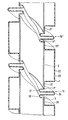
- the invention allows numerous design options. To illustrate its basic principle, one of them is shown schematically in the drawing and is described below. This shows a longitudinal section through a partial area of a protective tube designed according to the invention with a conductor foil of a device for electrically measuring the level of a liquid.
- the drawing shows a protective tube 1, in which a band-like conductor foil 2 with longitudinal edges 3 is arranged helically.
- This protective tube region 16, 16 ' consists two radially inwardly directed U-shaped pipe sections 17, 18 and an outwardly directed U-shaped pipe section 19 arranged between them.
- the protective tube 1 On both sides of the flexible protective tube area 16, 16 ', the protective tube 1 each has a short axially extending film contact area 20, 21, 20' against which the conductor film 2 bears.
- the transition from the film contact areas 20, 21 to the pipe section 17, 18 takes place in each case by a rugged 90 degree bend, so that the film 2, especially when it is inserted into the protective pipe 1, rests on the pipe sections 17, 18 with their longitudinal edges 3, 3 ', 3 ".
- These film areas 21, 20 'between the flexible protective tube areas 16, 16' are each connected by a radially recessed, rigid protective tube section 22. In order to ensure that liquid can get against the outer surface of the conductor surface 2, there are passage openings in the protective tube section 22 23 provided.
- the installation of the conductor foil 2 in the protective tube 1 is easily possible even with a longer protective tube length. It is only necessary to place the conductor foil 2 on two foil contact areas 20 ′, 21 between the flexible protective tube regions 16, 16 ′ and then to push the conductor foil 2 in from the end of the apron tube. The conductor foil 2 then automatically slides along the helical foil contact region 20, 20 'delimited by the flexible protective tube region 16, 16'.
- the tube sections 17, 18 are used to arrange a not shown extraction tube inside the protective tube 1 to keep it at a distance from the conductor foil 2.
- the outside diameter of the sampling tube must be slightly smaller than the free cross section between the inwardly directed tube sections 17, 18.
Landscapes
- Physics & Mathematics (AREA)
- Thermal Sciences (AREA)
- Fluid Mechanics (AREA)
- General Physics & Mathematics (AREA)
- Engineering & Computer Science (AREA)
- Power Engineering (AREA)
- Electromagnetism (AREA)
- Measurement Of Levels Of Liquids Or Fluent Solid Materials (AREA)
Description
- Die Erfindung bezieht sich auf eine Einrichtung zum elektrischen Messen des Niveaus einer in einem Behälter enthaltenen Flüssigkeit mit einer in die Flüssigkeit eingetauchten, von einem Schutzrohr umschlossenen Leiterfolie, wie einer temperaturabhängigen elektrisch fremd beheitzten Widerstandsfolie, deren von einer Auswerteschaltung erfassbarer Gesamtwiderstand von dem Flüssigkeitsniveau im Behälter abhängig ist oder einer zwei einen Kondensator bildenden, Leiter tragenden Kapazitätsfolie, wobei die Leiterfolie bandartig ausgebildet und durch an einer ihrer Längskanten angreifende Halteelemente wendelförmig, beidseitig an ihrer Oberfläche von der Flüssigkeit umspülbar in dem Schutzrohr gehalten ist und wobei die Längskanten der Leiterfolie durch eine entsprechend grosse Steigung von Windung zu Windung gegenseitigen Abstand haben.
- Eine solche Messeinrichtung ist Gegenstand des Patents DE-C-3235534, das eine Priorität vom 25.9.82 hat und am 29.3.84 veröffentlicht wurde, und bei dem es in erster Linie darauf ankam, eine Einrichtung zu schaffen, die eine Niveaumessung mit hoher Genauigkeit ermöglicht. Die gemäss dem obigen Patent vorgesehene wendelförmige Ausbildung der Leiterfolie ermöglicht eine wesentlich grössere Länge der Leiterfolie als es der linearen Eintauchtiefe entspricht. Dadurch wird die benetzbare Fläche der Leiterfolie gross, so dass das Auflösungsvermögen des Messbereiches entsprechend gross wird. Hiervon abgesehen erlaubt die wendelförmige Anordnung der Leiterfolie die Einrichtung als Ganzes in radialer Richtung in begrenztem Masse zu verbiegen, ohne dass es zu einer Beschädigung der Leiterfolie kommt.
- Aus DE-At-3137 153 ist die eingangs beschriebene Messeinrichtung - abgesehen von der Variante mit der Kapazitätsfolie - bekannt.
- Behälter, in denen ein Flüssigkeitsniveau gemessen werden muss, sind oft recht unregelmässig geformt. Kraftfahrzeugtanks haben häufig sehr komplizierte Formen, um den vorhandenen Platz optimal auszunutzen und ein möglichst grosses Tankvolumen zu ermöglichen. Solche Behälterausbildungen schliessen es oft aus, dass die Einrichtung zum elektrischen Messen des Flüssigkeitsniveaus geradlinig bis zur tiefsten Behälterstelle verlaufen kann. Es ist dann erforderlich, das Schutzrohr mit der Leiterfolie stärker zu verbiegen, damit es der Behälterkonstruktion folgen kann. Bei der Einrichtung gemäss dem obigen Patent war diese mögliche Biegsamkeit nicht in allen Fällen ausreichend.
- Der Erfindung liegt die Aufgabe zugrunde, eine Einrichtung der eingangs genannten Art so weiterzuentwickeln, dass unter Beibehaltung der hohen Messgenauigkeit ein radiales Verbiegen des Schutzrohres mit eingebauter Leiterfolie in möglichst grossem Masse möglich wird. Diese Aufgabe wird erfindungsgemäss durch die Merkmale des Anspruchs 1 gelöst.
- Dank der erfindungsgemässen Ausbildung ist das Schutzrohr 1 nur zwischen den die etnzetnen Gänge der Leiterfolie begrenzenden Längskanten der Leiterfolie biegsam. Dadurch kann das Schutzrohr in beträchtlichem Masse verbogen werden, ohne dass die Leiterfolie unzulässig stark gebogen werden muss und dadurch krumpeln oder reissen kann. Die erfindungsgemässe Einrichtung bedingt kein kompliziert geformtes Schutzrohr, vielmehr kann es sich bei diesem um ein einfaches, durch Extrusion oder Spritzgiessen geformtes Kunststoffrohr handeln.
- Von Vorteil ist es, wenn der biegsame Schutzrohrbereich zumindest einen u-förmig radial nach innen oder aussen verlaufenden Rohrabschnitt hat. Auf diese Weise wird die Biegsamkeit des Schutzrohres mit einfachen Mitteln in dem gewünschten Bereich erreicht. Ein Verbiegen des Schutzrohres ist mit geringem Kraftaufwand möglich.
- Ein besonders leichtes Verbiegen des Schutzrohres mit montierter Leiterfolie ist durch die im Anspruch 3 angegebenen Merkmale möglich. Die nach innen gerichteten u-förmigen Rohrabschnitte bilden Anlagekanten für die Längskanten der Leiterfolie. Dadurch kann die Leiterfolie leicht von einer Stirnseite her in das Schutzrohr eingeschoben werden.
- Eine unerwünscht grosse Beanspruchung der Leiterfolie durch Biegekräfte kann zuverlässig ausgeschlossen werden, wenn das Schutzrohr, wie im Anspruch 4 angegeben, ausgebildet ist. Die Folienanlagebereiche stützen die Leiterfolie gut ab und ermöglichen eine rasche Montage.
- Zur Erzielung einer hohen Messgenauigkeit ist es erforderlich, dass die Leiterfolie allseitig umspült wird. Dies ist leicht zu verwirklichen, indem in die biegesteifen Schutzrohrabschnitte Durchflussöffnungen vorgesehen werden.
- Wenn man koaxial in dem Schutzrohr der erfindungsgemässen Einrichtung ein Entnahmerohr anordnen will, dann muss dieses Entnahmerohr durch Distanzstücke am Schutzrohr gehalten sein, damit es nirgends die Leiterfolie berühren kann. Die erfindungsgemässen nach innen gerichteten Rohrabschnitte vermögen eine Doppelfunktion auszuüben. Abgesehen davon, dass sie den Biegebereich festlegen, können sie dazu dienen, das Schutzrohr zu distanzieren.
- Die Erfindung lässt zahlreiche Ausführungsmöglichkeiten zu. Zur Verdeutlichung ihres Grundprinzips ist eine davon schematisch in der Zeichnung dargestellt und wird nachfolgend beschrieben. Diese zeigt einen Längsschnitt durch einen erfindungsgemäss gestalteten Teilbereich eines Schutzrohres mit Leiterfolie einer Einrichtung zum elektrischen Messen des Niveaus einer Flüssigkeit.
- Die Zeichnung zeigt ein Schutzrohr 1, in das eine bandartige Leiterfolie 2 mit Längskanten 3 wendelförmig angeordnet ist.
- Die Steigung der Leiterfolie 2 von Windung zu Windung ist derart gross, dass zwischen den Längskanten 3, 3', 3" ausreichend viel Abstand ist, um dort einen wendelförmig verlaufenden biegsamen Schutzrohrbereich 16, 16' vorsehen zu können. Dieser Schutzrohrbereich 16, 16' besteht aus zwei radial nach innen gerichteten u-förmigen Rohrabschnitten 17, 18 und einem dazwischen angeordneten nach aussen gerichteten u-förmigen Rohrabschnitt 19.
- Beiderseits des biegsamen Schutzrohrbereiches 16, 16' hat das Schutzrohr 1 jeweils einen kurzen axial verlaufenden Folienanlagebereich 20, 21, 20', gegen den die Leiterfolie 2 anliegt. Der Übergang von den Folienanlagebereichen 20, 21 zum Rohrabschnitt 17, 18 erfolgt jeweils durch eine schroffe 90 Grad-Umbiegung, damit die Folie 2 vor allem beim Einschieben in das Schutzrohr 1 sich auf den Rohrabschnitten 17, 18 mit ihren Längskanten 3, 3', 3" abstützen kann. Diese Folienbereiche 21, 20' zwischen den biegsamen Schutzrohrbereichen 16,16'sind jeweiis durch einen radial zurückspringenden biegesteifen Schutzrohrabschnitt 22 verbunden. Um zu erreichen, dass Flüssigkeit gegen die Aussenmantelfläche der Leiterfläche 2 gelangen kann, sind im Schutzrohrabschnitt 22 Durchlassöffnungen 23 vorgesehen.
- Der Einbau der Leiterfolie 2 in das Schutzrohr 1 ist auch bei grösserer Schutzrohrlänge leicht möglich. Man braucht die Leiterfolie 2 lediglich auf zwei Folienanlagebereiche 20', 21 zwischen den biegsamen Schutzrohrbereichen 16, 16' zu legen und dann die Leiterfolie 2 von der Schturzrohrstirnseite her nachzuschieben. Die Leiterfolie 2 rutscht dann selbsttätig entlang des durch den biegsamen Schutzrohrbereich 16, 16' begrenzten wendelförmigen Folienanlagebereichs 20, 20'.
- Die Rohrabschnitte 17, 18 dienen bei Anordnung eines nicht dargestellten Entnahmerohres im Inneren des Schutzrohres 1 dazu, dieses auf Abstand von der Leiterfolie 2 zu halten. Der Aussendurchmesser des Entnahmerohres muss hierzu geringfügig kleiner sein als der freie Querschnitt zwischen den nach innen gerichteten Rohrabschnitten 17, 18.
Claims (6)
Applications Claiming Priority (2)
| Application Number | Priority Date | Filing Date | Title |
|---|---|---|---|
| DE3321559A DE3321559A1 (de) | 1983-06-15 | 1983-06-15 | Einrichtung zum elektrischen messen eines fluessigkeitsniveaus |
| DE3321559 | 1983-06-15 |
Publications (2)
| Publication Number | Publication Date |
|---|---|
| EP0129650A1 EP0129650A1 (de) | 1985-01-02 |
| EP0129650B1 true EP0129650B1 (de) | 1986-10-08 |
Family
ID=6201523
Family Applications (1)
| Application Number | Title | Priority Date | Filing Date |
|---|---|---|---|
| EP84103891A Expired EP0129650B1 (de) | 1983-06-15 | 1984-04-07 | Einrichtung zum elektrischen Messen eines Flüssigkeitsniveaus |
Country Status (5)
| Country | Link |
|---|---|
| US (1) | US4562733A (de) |
| EP (1) | EP0129650B1 (de) |
| JP (1) | JPS6010121A (de) |
| AU (1) | AU567740B2 (de) |
| DE (2) | DE3321559A1 (de) |
Families Citing this family (8)
| Publication number | Priority date | Publication date | Assignee | Title |
|---|---|---|---|---|
| GB8506716D0 (en) * | 1985-03-15 | 1985-04-17 | Smiths Industries Plc | Mounts for probes |
| US4852616A (en) * | 1986-01-10 | 1989-08-01 | Mid-State Drainage Products, Inc. | Corrugated pipe |
| DE3706048A1 (de) * | 1987-02-25 | 1988-09-08 | Precitronic | Sonde fuer die bestimmung der treibstoffmenge in treibstofftanks |
| DE58901303D1 (de) * | 1988-03-08 | 1992-06-11 | Vsl Int Ag | Huellrohr. |
| US6053424A (en) * | 1995-12-21 | 2000-04-25 | Kimberly-Clark Worldwide, Inc. | Apparatus and method for ultrasonically producing a spray of liquid |
| US5971033A (en) * | 1996-04-12 | 1999-10-26 | Lanz; Werner | Profiled tube, corrugated hose or the like elongate portion with mutually parallel peripheral grooves |
| DE19851213C1 (de) * | 1998-11-06 | 2000-06-08 | Daimler Chrysler Ag | Kapazitive Sensoranordnung für ein als Dielektrikum wirkendes flüssiges oder gasförmiges Medium |
| JP3995470B2 (ja) * | 2001-12-25 | 2007-10-24 | カルソニックカンセイ株式会社 | フレキシブルチューブ |
Family Cites Families (7)
| Publication number | Priority date | Publication date | Assignee | Title |
|---|---|---|---|---|
| BE563400A (de) * | 1956-12-21 | |||
| US3050999A (en) * | 1957-08-20 | 1962-08-28 | Simmonds Precision Products | Capacity unit for liquid quantity gauges |
| US3324722A (en) * | 1964-12-23 | 1967-06-13 | Atomic Power Dev Ass Inc | Continuous fluid level measuring apparatus |
| DE2922093A1 (de) * | 1979-05-31 | 1980-12-11 | Interatom | Flexibler, kontinuierlicher fuellstandsmesser fuer elektrisch leitende fluessigkeiten |
| DE3108969C2 (de) * | 1981-03-10 | 1986-01-09 | Draloric Electronic GmbH, 8672 Selb | Elektrothermische Füllstandsanzeigevorrichtung |
| DE3137153C2 (de) * | 1981-09-18 | 1986-04-24 | Telefunken electronic GmbH, 7100 Heilbronn | Vorrichtung zur Füllstandsmessung |
| DE3235534C2 (de) * | 1982-09-25 | 1984-10-11 | Vdo Adolf Schindling Ag, 6000 Frankfurt | Einrichtung zum elektrischen Messen eines Flüssigkeitsniveaus |
-
1983
- 1983-06-15 DE DE3321559A patent/DE3321559A1/de not_active Withdrawn
-
1984
- 1984-04-07 DE DE8484103891T patent/DE3460911D1/de not_active Expired
- 1984-04-07 EP EP84103891A patent/EP0129650B1/de not_active Expired
- 1984-05-18 AU AU28404/84A patent/AU567740B2/en not_active Ceased
- 1984-06-13 JP JP59120095A patent/JPS6010121A/ja active Pending
- 1984-06-15 US US06/620,851 patent/US4562733A/en not_active Expired - Fee Related
Also Published As
| Publication number | Publication date |
|---|---|
| DE3321559A1 (de) | 1984-12-20 |
| DE3460911D1 (en) | 1986-11-13 |
| JPS6010121A (ja) | 1985-01-19 |
| AU567740B2 (en) | 1987-12-03 |
| AU2840484A (en) | 1984-12-20 |
| EP0129650A1 (de) | 1985-01-02 |
| US4562733A (en) | 1986-01-07 |
Similar Documents
| Publication | Publication Date | Title |
|---|---|---|
| EP0129009B1 (de) | Einrichtung zum elektrischen Messen eines Flüssigkeitsniveaus | |
| DE2607563C2 (de) | Tropfbewässerungsschlauch | |
| EP0129650B1 (de) | Einrichtung zum elektrischen Messen eines Flüssigkeitsniveaus | |
| DE3017574A1 (de) | Koaxiales rohrsystem fuer die waermeuebertragung zwischen fluessigkeiten oder gasen | |
| DE3124875A1 (de) | "messsonde" | |
| EP1354211A1 (de) | Pipettiervorrichtung | |
| EP0130291B1 (de) | Behälter mit einer Einrichtung zum elektrischen Messen des Niveaus einer in ihm enthaltenen Flüssigkeit | |
| DE102006045940A1 (de) | Abstandshalter für Koaxialinnenleiter | |
| EP0143167B1 (de) | Einrichtung zum elektrischen Messen eines Flüssigkeitsniveaus | |
| DE2809647C2 (de) | Kugelumlaufschraubgetriebe | |
| DE3235534C2 (de) | Einrichtung zum elektrischen Messen eines Flüssigkeitsniveaus | |
| DE3214705C2 (de) | ||
| DE2513226C2 (de) | Vorrichtung zum Halten und Abstützen der Stäbe eines Stabbündels in der Hülle eines Kernreaktor-Brennelements | |
| EP2112441A2 (de) | Solarabsorber und zugehöriger Solarkollektor | |
| DE2512664C2 (de) | Vorrichtung zum Halten und Stützen der Stäbe eines Stabbündels in der Hülle eines Kernreaktor-Brennelements | |
| DE3137153C2 (de) | Vorrichtung zur Füllstandsmessung | |
| DE102011088118B4 (de) | Messanordnung mit einer Aufnahme für einen biegsamen Temperaturfühler | |
| CH682845A5 (de) | Kapazitive Niveaumess-Sonde sowie deren Verwendung. | |
| AT375496B (de) | Kabelkanalrohranordnung | |
| DE3718199C2 (de) | Vorrichtung zur Abtastung des Flüssigkeitspegels in einem Tank | |
| DE2505620C2 (de) | Verbindungsstück zur Aufnahme einer rohrförmigen Führung | |
| DE3635469A1 (de) | Flexibler verbindungsschlauch zwischen einem kraftstoffbehaelter und einem einfuellstutzen | |
| EP0125430A2 (de) | Füllmaterial aus Kunststoff für Tropfkörper | |
| DE19616354A1 (de) | Rohrleitungsstück mit elektrischer Leitung | |
| DE102018112471A1 (de) | Fluidheizer |
Legal Events
| Date | Code | Title | Description |
|---|---|---|---|
| PUAI | Public reference made under article 153(3) epc to a published international application that has entered the european phase |
Free format text: ORIGINAL CODE: 0009012 |
|
| 17P | Request for examination filed |
Effective date: 19840901 |
|
| AK | Designated contracting states |
Designated state(s): DE FR GB IT NL SE |
|
| 17Q | First examination report despatched |
Effective date: 19860320 |
|
| GRAA | (expected) grant |
Free format text: ORIGINAL CODE: 0009210 |
|
| AK | Designated contracting states |
Kind code of ref document: B1 Designated state(s): DE FR GB IT NL SE |
|
| REF | Corresponds to: |
Ref document number: 3460911 Country of ref document: DE Date of ref document: 19861113 |
|
| ET | Fr: translation filed | ||
| ITF | It: translation for a ep patent filed | ||
| PLBE | No opposition filed within time limit |
Free format text: ORIGINAL CODE: 0009261 |
|
| STAA | Information on the status of an ep patent application or granted ep patent |
Free format text: STATUS: NO OPPOSITION FILED WITHIN TIME LIMIT |
|
| 26N | No opposition filed | ||
| PGFP | Annual fee paid to national office [announced via postgrant information from national office to epo] |
Ref country code: SE Payment date: 19890320 Year of fee payment: 6 Ref country code: DE Payment date: 19890320 Year of fee payment: 6 |
|
| PGFP | Annual fee paid to national office [announced via postgrant information from national office to epo] |
Ref country code: FR Payment date: 19890330 Year of fee payment: 6 |
|
| PGFP | Annual fee paid to national office [announced via postgrant information from national office to epo] |
Ref country code: GB Payment date: 19890331 Year of fee payment: 6 |
|
| ITTA | It: last paid annual fee | ||
| PGFP | Annual fee paid to national office [announced via postgrant information from national office to epo] |
Ref country code: NL Payment date: 19890430 Year of fee payment: 6 |
|
| PG25 | Lapsed in a contracting state [announced via postgrant information from national office to epo] |
Ref country code: GB Effective date: 19900407 |
|
| PG25 | Lapsed in a contracting state [announced via postgrant information from national office to epo] |
Ref country code: SE Effective date: 19900408 |
|
| PG25 | Lapsed in a contracting state [announced via postgrant information from national office to epo] |
Ref country code: NL Effective date: 19901101 |
|
| GBPC | Gb: european patent ceased through non-payment of renewal fee | ||
| NLV4 | Nl: lapsed or anulled due to non-payment of the annual fee | ||
| PG25 | Lapsed in a contracting state [announced via postgrant information from national office to epo] |
Ref country code: FR Effective date: 19901228 |
|
| PG25 | Lapsed in a contracting state [announced via postgrant information from national office to epo] |
Ref country code: DE Effective date: 19910101 |
|
| REG | Reference to a national code |
Ref country code: FR Ref legal event code: ST |
|
| EUG | Se: european patent has lapsed |
Ref document number: 84103891.2 Effective date: 19910115 |