EP0129677A2 - Centre d'usinage pour travaux de fraisage et de perçage - Google Patents
Centre d'usinage pour travaux de fraisage et de perçage Download PDFInfo
- Publication number
- EP0129677A2 EP0129677A2 EP84104888A EP84104888A EP0129677A2 EP 0129677 A2 EP0129677 A2 EP 0129677A2 EP 84104888 A EP84104888 A EP 84104888A EP 84104888 A EP84104888 A EP 84104888A EP 0129677 A2 EP0129677 A2 EP 0129677A2
- Authority
- EP
- European Patent Office
- Prior art keywords
- headstock
- machining center
- tool
- main
- center according
- Prior art date
- Legal status (The legal status is an assumption and is not a legal conclusion. Google has not performed a legal analysis and makes no representation as to the accuracy of the status listed.)
- Withdrawn
Links
Images
Classifications
-
- B—PERFORMING OPERATIONS; TRANSPORTING
- B23—MACHINE TOOLS; METAL-WORKING NOT OTHERWISE PROVIDED FOR
- B23Q—DETAILS, COMPONENTS, OR ACCESSORIES FOR MACHINE TOOLS, e.g. ARRANGEMENTS FOR COPYING OR CONTROLLING; MACHINE TOOLS IN GENERAL CHARACTERISED BY THE CONSTRUCTION OF PARTICULAR DETAILS OR COMPONENTS; COMBINATIONS OR ASSOCIATIONS OF METAL-WORKING MACHINES, NOT DIRECTED TO A PARTICULAR RESULT
- B23Q3/00—Devices holding, supporting, or positioning work or tools, of a kind normally removable from the machine
- B23Q3/155—Arrangements for automatic insertion or removal of tools, e.g. combined with manual handling
- B23Q3/157—Arrangements for automatic insertion or removal of tools, e.g. combined with manual handling of rotary tools
- B23Q3/15713—Arrangements for automatic insertion or removal of tools, e.g. combined with manual handling of rotary tools a transfer device taking a single tool from a storage device and inserting it in a spindle
- B23Q3/1572—Arrangements for automatic insertion or removal of tools, e.g. combined with manual handling of rotary tools a transfer device taking a single tool from a storage device and inserting it in a spindle the storage device comprising rotating or circulating storing means
- B23Q3/15726—Arrangements for automatic insertion or removal of tools, e.g. combined with manual handling of rotary tools a transfer device taking a single tool from a storage device and inserting it in a spindle the storage device comprising rotating or circulating storing means the storage means rotating or circulating in a plane parallel to the axis of the spindle
- B23Q3/1574—Arrangements for automatic insertion or removal of tools, e.g. combined with manual handling of rotary tools a transfer device taking a single tool from a storage device and inserting it in a spindle the storage device comprising rotating or circulating storing means the storage means rotating or circulating in a plane parallel to the axis of the spindle the axis of the stored tools being arranged perpendicularly to the rotating or circulating plane of the storage means
-
- B—PERFORMING OPERATIONS; TRANSPORTING
- B23—MACHINE TOOLS; METAL-WORKING NOT OTHERWISE PROVIDED FOR
- B23B—TURNING; BORING
- B23B39/00—General-purpose boring or drilling machines or devices; Sets of boring and/or drilling machines
- B23B39/16—Drilling machines with a plurality of working-spindles; Drilling automatons
-
- B—PERFORMING OPERATIONS; TRANSPORTING
- B23—MACHINE TOOLS; METAL-WORKING NOT OTHERWISE PROVIDED FOR
- B23Q—DETAILS, COMPONENTS, OR ACCESSORIES FOR MACHINE TOOLS, e.g. ARRANGEMENTS FOR COPYING OR CONTROLLING; MACHINE TOOLS IN GENERAL CHARACTERISED BY THE CONSTRUCTION OF PARTICULAR DETAILS OR COMPONENTS; COMBINATIONS OR ASSOCIATIONS OF METAL-WORKING MACHINES, NOT DIRECTED TO A PARTICULAR RESULT
- B23Q7/00—Arrangements for handling work specially combined with or arranged in, or specially adapted for use in connection with, machine tools, e.g. for conveying, loading, positioning, discharging, sorting
- B23Q7/14—Arrangements for handling work specially combined with or arranged in, or specially adapted for use in connection with, machine tools, e.g. for conveying, loading, positioning, discharging, sorting co-ordinated in production lines
- B23Q7/1426—Arrangements for handling work specially combined with or arranged in, or specially adapted for use in connection with, machine tools, e.g. for conveying, loading, positioning, discharging, sorting co-ordinated in production lines with work holders not rigidly fixed to the transport devices
- B23Q7/1431—Work holder changers
Definitions
- the invention relates to a machining center for milling and drilling work, consisting of a headstock which can be moved horizontally longitudinally on the machine stand, a table support which can be moved horizontally and transversely to the headstock axis, a tool magazine and at least one device for automatic tool change.
- Machining centers of this type are generally used in large series production for multi-stage automatic machining of workpieces, with several milling and drilling processes being carried out in different workpiece positions due to the high degree of automation on the workpiece being fed and clamped.
- white Automated sequence of various handling and machining processes the performance of such a machine center is considerably higher than that of normal NC-controlled milling and drilling machines, since further increases in performance find their limits in the sequence of the various machining processes.
- the object of the invention is to provide a machining center for milling and drilling work of the type specified, the machining performance of which is increased many times over that of conventional machines.
- this object is achieved in that a plurality of horizontal main spindles are arranged axially parallel to one another in the headstock, that at least one turntable is arranged on the table support and is designed to receive at least one workpiece, and that the device for changing tools for simultaneously receiving and transferring one tool per Main spindle is formed.
- the parallel arrangement of several main spindles in the headstock makes it possible to simultaneously process a number of workpieces corresponding to the number of main spindles, which are positioned on the workpiece turntables in a suitable number and with suitable intermediate distances.
- two main spindles can be arranged axially parallel and vertically one above the other in the headstock.
- the processing is done only a single turntable is required, on which two workpieces are placed vertically one above the other at a distance. vertical distance corresponding to the main spindles.
- the tool magazine can be arranged as a chain magazine on the side of the machine stand and the device for changing tools has four grippers for a simultaneous tool change of the two main spindles.
- This changing device is designed to be displaceable in the longitudinal direction of the headstock in order to release the two tools from their seat in the main spindle with two grippers and to take two new, identical tools from the chain magazine.
- a half turn of the tool changer in its extended state around the change axis inclined at 45 ° to the longitudinal axis of the spindle brings the new tools in front of the main spindles and at the same time the used tools in front of the corresponding receptacles of the chain magazine.
- two main spindles can also be arranged horizontally next to one another in a common spindle spindle or in two axially parallel spindle bolts.
- two workpieces can be machined in three axes at the same time, two rotary tables can be mounted side by side on the table support, the horizontal distance between the two table centers corresponding to the horizontal distance between the two main spindles.
- the tool magazine can be mounted on the headstock in the form of a chain, a plate or another suitable storage device and the four-gripper tool changing device is in Movable in the longitudinal direction of the headstock and rotatable by 180 ° about its longitudinal axis inclined at 45 ° to the longitudinal axis of the headstock.
- This version is characterized by a relatively high rigidity and guidance accuracy, because the guide strips have a wide horizontal spacing due to the relatively large width of the headstock.
- a further development of the machining center according to the invention which is particularly expedient in terms of machining performance: is characterized in that a total of four main spindles with the same vertical and horizontal spacing are arranged in one or two spindle pieces, with at least two rotary tables next to one another at a central axis spacing on the table support are arranged, which corresponds to the horizontal distance of the main spindle axes.
- Each rotary table is designed to hold two workpieces vertically one above the other.
- a tool magazine and a tool changing device are provided on each side of the spindle piece.
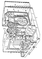
- a machine base 2, a control cabinet 3, a pallet transfer 4 and a capsule housing 5 with windows are arranged on a continuous base 1.
- a headstock 6 is arranged horizontally in guide rails 7 in the direction of its longitudinal axis and carries a main drive 8 with gear 9 in its rear end section.
- main drive 8 with gear 9 in its rear end section.
- main spindles 10 to 13 with the same vertical and horizontal spacing are arranged side by side and one above the other, which are driven jointly and synchronously by the main drive 8, 9.
- This table support 16 carries on its front face a workpiece carriage 17, on which two rotary tables 18, 19 are arranged with a center distance which corresponds exactly to the center distance of the main spindles 11, 13 and 10, 12, respectively. This means that the axes of the spindles 10, 11 and 12, 13 intersect the vertical axes of the rotary tables 18 and 19, respectively.
- a pallet 20, 21 is centered on each turntable 18 and 19, each of which carries two workpieces, not shown, arranged vertically one above the other.
- magazine 25, 26 in on each longitudinal side of the machine stand 2.
- Both magazine chains 27 and 28 are of exactly the same design and are driven synchronously.
- these magazine chains each have the same tools for the Main spindles 10, 11 and 12, 13 are arranged, which can be installed or removed simultaneously by two changing devices 39, 40.
- These tool changing devices 39, 40 have vertical support plates 37, 38 which run at a horizontal angle of 45 ° to the longitudinal axis of the headstock. Both support plates 39, 40 are horizontally displaceable in the direction of the longitudinal axis of the headstock.
- Gripper arms attached to the support plates 39, 40 carry tool grippers 41 to 43, each of which enclose paired angles of 90 ° and which are used for simultaneously gripping the tools clamped in the spindles 12, 13 and 10, 11 and according to predetermined relative movements for gripping corresponding tools in serve the chain magazine 26.
- Each tool changer 40, 41 can be rotated in its extended position about its central axis 45, 46, which is inclined at an angle of 45 ° to the longitudinal axis of the headstock, so that the "used" tools are made by moving the tool changer 39, 40 in the longitudinal axis of the headstock the main spindles 10, 11 or 12, 13 and pulled out of the respective magazine simultaneously and in pairs and after the 180 ° rotation can be exchanged for the two same tools previously removed from the chain magazine 26.
- the automatic workpiece transfer 4 comprises a support frame 50 which can be displaced horizontally on the base 1, between the fork-shaped carriers 51 of which two pallets 52, 54 with - not shown - workpieces pre-mortised in pairs are accommodated are.
- Two pallet receptacles 54, 55 are - as shown - empty and serve to remove the two pallets 20, 21 after the processing operations have ended.
- the workpiece slides 17 can be displaced relative to one another in order to change the pallet or workpiece, so that the automatic transfer of the pallet 50 does not have to extend too far beyond the base 1, which would be the case, if only the transfer frame 50 moves and the table slide 17 would be horizontally immovably connected to the support 16.
- the invention is not restricted to the exemplary embodiment shown and described above.
- structurally simpler versions are readily possible, in which only one pair of main spindles is arranged axially parallel next to one another in the headstock, wherein either these two main spindles can be provided vertically one above the other or horizontally next to one another. If two main spindles are arranged vertically one above the other, this is naturally not necessary one turntable each and one of the tool magazines on the side of the stand with the corresponding tool changer.
- two main spindles When arranging two main spindles horizontally next to each other, e.g. B.
- the tool changer required in this case corresponds in its basic structure to the tool changers 40, 41 shown, but is mounted on the upper end edge of the headstock, its central axis running at a vertical angle of 45 ° to the longitudinal axis of the headstock. It is also possible to mount two headstocks parallel to one another on the machine stand, in which case either one or two spindles can be arranged one above the other.
- a major advantage of the machine center according to the invention results from the paired arrangement of the main spindles with a corresponding choice of their direction of rotation through the possibility of automatic compensation of oscillations and vibrations during the machining processes.
- the main advantage of the invention is that twice or four times the number of workpieces can be machined in one machine with approximately the same amount of time and effort, which was previously not possible.
Landscapes
- Engineering & Computer Science (AREA)
- Mechanical Engineering (AREA)
- Automatic Tool Replacement In Machine Tools (AREA)
- Turning (AREA)
Applications Claiming Priority (2)
| Application Number | Priority Date | Filing Date | Title |
|---|---|---|---|
| DE19833322877 DE3322877A1 (de) | 1983-06-24 | 1983-06-24 | Bearbeitungszentrum fuer fraes- und bohrarbeiten |
| DE3322877 | 1983-06-24 |
Publications (2)
| Publication Number | Publication Date |
|---|---|
| EP0129677A2 true EP0129677A2 (fr) | 1985-01-02 |
| EP0129677A3 EP0129677A3 (fr) | 1986-01-08 |
Family
ID=6202350
Family Applications (1)
| Application Number | Title | Priority Date | Filing Date |
|---|---|---|---|
| EP84104888A Withdrawn EP0129677A3 (fr) | 1983-06-24 | 1984-05-02 | Centre d'usinage pour travaux de fraisage et de perçage |
Country Status (2)
| Country | Link |
|---|---|
| EP (1) | EP0129677A3 (fr) |
| DE (1) | DE3322877A1 (fr) |
Cited By (7)
| Publication number | Priority date | Publication date | Assignee | Title |
|---|---|---|---|---|
| DE3605470A1 (de) * | 1985-02-25 | 1986-08-28 | Yamazaki Machinery Works, Ltd., Ooguchi, Aichi | Mehrflaechenbearbeitungs-werkzeugmaschine |
| EP0360168A3 (en) * | 1988-09-20 | 1990-11-22 | Chiron-Werke Gmbh & Co. Kg | Machine tool |
| FR2705266A1 (fr) * | 1993-05-13 | 1994-11-25 | Jobs Spa | Cellule de travail comprenant deux machines-outils et un changeur d'outils commun. |
| DE19826507A1 (de) * | 1998-06-15 | 1999-12-16 | Wilfried Taubner | Bearbeitungsmodulsystem |
| EP1122027A1 (fr) * | 2000-02-04 | 2001-08-08 | VIGEL S.p.A. | Dispositif pour usiner des étriers et des supports de freins à disque pour automobiles |
| EP1935559A3 (fr) * | 2006-12-19 | 2008-07-30 | Nisshinbo Industries, Inc. | Centre d'usinage avec magasin d'outils en forme de chaîne |
| US7726375B2 (en) | 2007-06-13 | 2010-06-01 | Nisshinbo Industries, Inc. | Laminator |
Families Citing this family (1)
| Publication number | Priority date | Publication date | Assignee | Title |
|---|---|---|---|---|
| DE19608350A1 (de) * | 1996-03-05 | 1997-09-11 | Hueller Hille Gmbh | Verfahren zur Bearbeitung von Werkstücken mit zwei parallel zueinander angeordneten Arbeitsspindeln auf einem Spindelstock und Werkzeugmaschine zur Durchführung des Verfahrens |
Family Cites Families (9)
| Publication number | Priority date | Publication date | Assignee | Title |
|---|---|---|---|---|
| DE1477397A1 (de) * | 1963-10-04 | 1969-03-13 | Hueller Gmbh K | Mehrspindelbohrmaschine |
| US3286595A (en) * | 1964-09-26 | 1966-11-22 | Wollenhaupt Jakob | Machine tool |
| FR1485510A (fr) * | 1964-11-05 | 1967-06-23 | Derefa Etablissement Pour Le D | Fraiseuse-aléseuse à poupée mobile rotative |
| FR1567899A (fr) * | 1967-09-22 | 1969-05-23 | ||
| US3849018A (en) * | 1973-01-31 | 1974-11-19 | Sundstrand Corp | Multiple spindle head |
| DE2833145A1 (de) * | 1978-07-28 | 1980-02-07 | Ewertowski Ing Buero | Waagerecht-bohr-fraesmaschine |
| US4427325A (en) * | 1978-10-25 | 1984-01-24 | Kearney & Trecker Corporation | Multiple spindle toolhead |
| DE2852846C2 (de) * | 1978-12-07 | 1985-03-07 | Eksperimental'nyj naučno-issledovatel'skij institut metallorežuščich stankov, Moskau/Moskva | Werkzeugmaschine mit automatisch gesteuerten Werkzeug- und Palettenwechslern |
| DE3042564C2 (de) * | 1980-11-12 | 1982-09-02 | Grundfos Pumpenfabrik GmbH, 2362 Wahlstedt | Mehrspindel-Werkzeugmaschine |
-
1983
- 1983-06-24 DE DE19833322877 patent/DE3322877A1/de not_active Withdrawn
-
1984
- 1984-05-02 EP EP84104888A patent/EP0129677A3/fr not_active Withdrawn
Cited By (7)
| Publication number | Priority date | Publication date | Assignee | Title |
|---|---|---|---|---|
| DE3605470A1 (de) * | 1985-02-25 | 1986-08-28 | Yamazaki Machinery Works, Ltd., Ooguchi, Aichi | Mehrflaechenbearbeitungs-werkzeugmaschine |
| EP0360168A3 (en) * | 1988-09-20 | 1990-11-22 | Chiron-Werke Gmbh & Co. Kg | Machine tool |
| FR2705266A1 (fr) * | 1993-05-13 | 1994-11-25 | Jobs Spa | Cellule de travail comprenant deux machines-outils et un changeur d'outils commun. |
| DE19826507A1 (de) * | 1998-06-15 | 1999-12-16 | Wilfried Taubner | Bearbeitungsmodulsystem |
| EP1122027A1 (fr) * | 2000-02-04 | 2001-08-08 | VIGEL S.p.A. | Dispositif pour usiner des étriers et des supports de freins à disque pour automobiles |
| EP1935559A3 (fr) * | 2006-12-19 | 2008-07-30 | Nisshinbo Industries, Inc. | Centre d'usinage avec magasin d'outils en forme de chaîne |
| US7726375B2 (en) | 2007-06-13 | 2010-06-01 | Nisshinbo Industries, Inc. | Laminator |
Also Published As
| Publication number | Publication date |
|---|---|
| DE3322877A1 (de) | 1985-01-10 |
| EP0129677A3 (fr) | 1986-01-08 |
Similar Documents
| Publication | Publication Date | Title |
|---|---|---|
| DE3035451C2 (fr) | ||
| DE19503482C2 (de) | Werkzeugmaschine mit einem Ständer, an dem zwei Spindelstöcke unabhängig voneinander verfahrbar sind | |
| DE3519706C2 (fr) | ||
| DE2739534C2 (de) | Werkzeugwechselvorrichtung | |
| DE2325629C2 (de) | Werkzeugmagazin für eine Werkzeugmaschine | |
| EP1291122A2 (fr) | Centre d'usinage pour fraisage et forage | |
| WO1993005926A1 (fr) | Centre d'usinage servant a usiner une piece a l'aide d'au moins deux outils interchangeables | |
| DE3427245A1 (de) | Werkzeugmaschine | |
| EP0111046B2 (fr) | Dispositif de changement d'outil pour une machine-outil à broches multiples | |
| EP1413395A1 (fr) | Machine-outil | |
| DE3330442A1 (de) | Verfahren und vorrichtung zum automatischen werkzeugwechsel an einer mehrspindel-werkzeugmaschine | |
| DE3722180C2 (de) | Transfermaschine | |
| DE3327512C2 (fr) | ||
| EP0064766A2 (fr) | Méthode et dispositif pour le travail de pièces ayant une symétrie de rotation | |
| DE3136017C1 (de) | Drehmaschine | |
| EP0129677A2 (fr) | Centre d'usinage pour travaux de fraisage et de perçage | |
| EP1511596A1 (fr) | Tour multibroche | |
| EP1346788A2 (fr) | Centre d'usinage | |
| DE19858791A1 (de) | Plattenbearbeitungsmaschine | |
| DD153337A5 (de) | Bearbeitungsmaschine | |
| EP1291125A2 (fr) | Méthode pour l'approvisionnement de magasins à outils d'un dispositif d' usinage de pièces | |
| DE3022717A1 (de) | Werkzeugmaschine mit einer automatischen werkzeugwechselvorrichtung | |
| DE2636986B2 (de) | Drehmaschine | |
| DE2653928A1 (de) | Bearbeitungszentrum | |
| WO1981000688A1 (fr) | Machine-outil avec changement automatique de l'outil |
Legal Events
| Date | Code | Title | Description |
|---|---|---|---|
| PUAI | Public reference made under article 153(3) epc to a published international application that has entered the european phase |
Free format text: ORIGINAL CODE: 0009012 |
|
| AK | Designated contracting states |
Designated state(s): CH FR GB IT LI |
|
| PUAL | Search report despatched |
Free format text: ORIGINAL CODE: 0009013 |
|
| AK | Designated contracting states |
Designated state(s): CH FR GB IT LI |
|
| STAA | Information on the status of an ep patent application or granted ep patent |
Free format text: STATUS: THE APPLICATION IS DEEMED TO BE WITHDRAWN |
|
| 18D | Application deemed to be withdrawn |
Effective date: 19860909 |
|
| RIN1 | Information on inventor provided before grant (corrected) |
Inventor name: BABEL, WERNER |