EP0129683A1 - Datumschaltwerk für Uhren - Google Patents
Datumschaltwerk für Uhren Download PDFInfo
- Publication number
- EP0129683A1 EP0129683A1 EP84105243A EP84105243A EP0129683A1 EP 0129683 A1 EP0129683 A1 EP 0129683A1 EP 84105243 A EP84105243 A EP 84105243A EP 84105243 A EP84105243 A EP 84105243A EP 0129683 A1 EP0129683 A1 EP 0129683A1
- Authority
- EP
- European Patent Office
- Prior art keywords
- jumper
- mobile
- coupling means
- toothing
- crown
- Prior art date
- Legal status (The legal status is an assumption and is not a legal conclusion. Google has not performed a legal analysis and makes no representation as to the accuracy of the status listed.)
- Withdrawn
Links
- 230000007246 mechanism Effects 0.000 title claims abstract description 28
- 230000008878 coupling Effects 0.000 claims abstract description 13
- 238000010168 coupling process Methods 0.000 claims abstract description 13
- 238000005859 coupling reaction Methods 0.000 claims abstract description 13
- 230000005540 biological transmission Effects 0.000 abstract description 3
- 230000008859 change Effects 0.000 description 10
- 238000004804 winding Methods 0.000 description 3
- 230000009471 action Effects 0.000 description 2
- 238000010276 construction Methods 0.000 description 2
- 230000007423 decrease Effects 0.000 description 2
- 238000006073 displacement reaction Methods 0.000 description 2
- FGRBYDKOBBBPOI-UHFFFAOYSA-N 10,10-dioxo-2-[4-(N-phenylanilino)phenyl]thioxanthen-9-one Chemical compound O=C1c2ccccc2S(=O)(=O)c2ccc(cc12)-c1ccc(cc1)N(c1ccccc1)c1ccccc1 FGRBYDKOBBBPOI-UHFFFAOYSA-N 0.000 description 1
- 230000008901 benefit Effects 0.000 description 1
- 230000000903 blocking effect Effects 0.000 description 1
- 230000006866 deterioration Effects 0.000 description 1
- 230000008030 elimination Effects 0.000 description 1
- 238000003379 elimination reaction Methods 0.000 description 1
- 230000009191 jumping Effects 0.000 description 1
- 230000004048 modification Effects 0.000 description 1
- 238000012986 modification Methods 0.000 description 1
- 239000010453 quartz Substances 0.000 description 1
- 230000009467 reduction Effects 0.000 description 1
- 230000035939 shock Effects 0.000 description 1
- VYPSYNLAJGMNEJ-UHFFFAOYSA-N silicon dioxide Inorganic materials O=[Si]=O VYPSYNLAJGMNEJ-UHFFFAOYSA-N 0.000 description 1
- 230000008685 targeting Effects 0.000 description 1
- 230000002747 voluntary effect Effects 0.000 description 1
Images


Classifications
-
- G—PHYSICS
- G04—HOROLOGY
- G04B—MECHANICALLY-DRIVEN CLOCKS OR WATCHES; MECHANICAL PARTS OF CLOCKS OR WATCHES IN GENERAL; TIME PIECES USING THE POSITION OF THE SUN, MOON OR STARS
- G04B11/00—Click devices; Stop clicks; Clutches
-
- G—PHYSICS
- G04—HOROLOGY
- G04B—MECHANICALLY-DRIVEN CLOCKS OR WATCHES; MECHANICAL PARTS OF CLOCKS OR WATCHES IN GENERAL; TIME PIECES USING THE POSITION OF THE SUN, MOON OR STARS
- G04B13/00—Gearwork
- G04B13/02—Wheels; Pinions; Spindles; Pivots
- G04B13/021—Wheels; Pinions; Spindles; Pivots elastic fitting with a spindle, axis or shaft
-
- G—PHYSICS
- G04—HOROLOGY
- G04B—MECHANICALLY-DRIVEN CLOCKS OR WATCHES; MECHANICAL PARTS OF CLOCKS OR WATCHES IN GENERAL; TIME PIECES USING THE POSITION OF THE SUN, MOON OR STARS
- G04B19/00—Indicating the time by visual means
- G04B19/24—Clocks or watches with date or week-day indicators, i.e. calendar clocks or watches; Clockwork calendars
- G04B19/243—Clocks or watches with date or week-day indicators, i.e. calendar clocks or watches; Clockwork calendars characterised by the shape of the date indicator
- G04B19/247—Clocks or watches with date or week-day indicators, i.e. calendar clocks or watches; Clockwork calendars characterised by the shape of the date indicator disc-shaped
- G04B19/253—Driving or releasing mechanisms
- G04B19/25333—Driving or releasing mechanisms wherein the date indicators are driven or released mechanically by a clockwork movement
- G04B19/25353—Driving or releasing mechanisms wherein the date indicators are driven or released mechanically by a clockwork movement driven or released stepwise by the clockwork movement
Definitions
- the present invention relates to a calendar mechanism for a timepiece, and it relates more particularly to such an improved calendar mechanism so that its operation requires both minimum energy and minimum drive torque.
- the calendar mechanism of a timepiece is an element that consumes significant energy, and which opposes the drive device of the piece a significant resistant torque.
- the disc serving as an indicator member has a large diameter and a large inertia, and that for reasons of space, it is not possible to support it in its center by means of bearings with low coefficient of friction. , as is the case for most of the other cogs in a watch movement.
- the locking of the calendar disc is generally obtained by means of a jumper, solicited by means of a spring, in engagement with a internal toothing of the disc.
- a torque sufficient to overcome the action of the jumper spring, and to advance the disc by one notch.
- a spring is gradually armed, for example between 18 and 24 hours, and it is then released all at once at midnight to suddenly advance the disc by releasing the jumper.
- Swiss patent 591,720 proposes a calendar mechanism comprising a calendar crown driven once a day by a training mobile performing one revolution per 24 hours.
- a jumper mounted articulated on the frame of the mechanism is controlled by a cam provided on this same mobile to engage for most of the day against an internal toothing of the crown and to retract while the crown has to advance d 'a step.
- this mechanism has two major disadvantages.
- the calendar crown is driven by a simple tongue attached to the mobile making one revolution per 24 hours, and which collaborates with the internal toothing, with a substantially triangular profile of the crown.
- the calendar crown is no longer locked, and it risks moving, either by more than one step, or at less than a significant fraction of steps, which disturbs the reading of the date during the entire training phase of the calendar disc.
- the mobile which makes one revolution per 24 hours is provided with a second cam, which collaborates with a spout of the jumper to bring it back as quickly as possible to the position of engagement with the calendar crown , after the date change. This measure only reduces the period during which the risk of disregarding the date indication remains and, in addition, the accelerated movement of the jumper in the engagement position increases, even if only slightly, the torque requested from the mobile. drive at this time.
- the construction of the mechanism of the Swiss patent 591 720 follows directly from the known mechanisms, and it follows in particular that the mode of coupling of the jumper tooth with the internal toothing of the calendar crown is not optimal.
- the jumper tooth has inclined flanks, as found in conventional mechanisms, in which the action of the teeth of the disc on its flanks, at the time of change of date, must cause a movement of the jumper against the force of the winding spring of this jumper.
- this jumper can guarantee a correct locking of the calendar apart from the date changes, it must be applied against the internal toothing of the calendar crown with a significant force, corresponding approximately to the force of the winding spring of a classic long necklace.
- the normal support of the jumper of the device described being in reality provided by the mobile which makes one revolution per 24 hours, provided with its control cam, it follows that the jumper exercises, despite everything, in most of the day, a significant resistant couple on this mobile.
- the present invention proposes a mechanism of the type of that of the aforementioned patent, but which is further improved for on the one hand completely exclude the risks of untimely displacements of the calendar crown during the date changes, and for simultaneously , during the rest of the day, ensure perfect locking of the crown for lower stress on the engine.
- FIGS. 1 to 4 schematically represent the calendar mechanism in 4 of its successive positions during a change of date .
- FIG. 1 there is shown schematically a calendar mechanism comprising an indicator member constituted by a calendar crown 1, a driving mobile 2 performing one revolution per 24 hours, an intermediate mobile 3 which ensures the transmission of the mobile drive 2 to the calendar crown 1, and a jumper 4 articulated on the frame 5 of the mechanism.
- the coupling means which ensure the drive to the crown 1 are constituted by a finger 6 provided on the periphery of the driving mobile 2, by a first toothing 7 of the intermediate mobile 3, in which comes to engage, once per day, the finger 6, and by the internal toothing 8 of the calendar crown 1, which engages with a second toothing 9 of the intermediate mobile 3.
- the rocker-jumper 4 comprises a first elastic arm 10, the end of which is formed a tooth 11 which engages with the teeth 7 of the intermediate mobile 3.
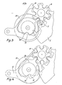
- a second arm 12 of the rocker-jumper 4 has a projection 13 which comes to bear on a cam 14 formed in the gap between the driving mobile 2 and the wheel 21 which entails.
- the cam 14 has a notch 15 in which the projection 13 engages to allow the jumper lever 4 to pivot in the direction of the arrow 16 when the driving mobile 2 must drive the intermediate mobile 3, the tooth 11 of the arm 10 then emerging from the teeth 7 of the intermediate mobile 3.
- the second arm 12 of the rocker-jumper 4 has an end spout 17, the spacing of the branch 10 is slightly less than the smallest diameter of the cam 14, so as to maintain the jumper 4 between the mobile 2 and its drive wheel 21, at the level of the cam 14, in a preassembled state of these elements.
- This arrangement appears more clearly in Figure 5.
- the coupling means allowing the transmission of the movement of the driving mobile 2 to the calendar crown 1 described above are given by way of example, and one could as well envisage the elimination of the intermediate mobile 3.
- the latter however has the advantage of being able to wear two teeth 7, 9 one of which is perfectly suited to its collaboration with the jumper tooth, and the other to the drive of the calendar crown.
- the respective profiles of the finger 6 of the driving mobile 2, and of the toothing 7 of the intermediate mobile 3, as well as those of the toothing 9 of this intermediate mobile 3 and of the toothing 8 of the calendar crown 1 are defined so as to allow engagement of the self-locking type of these different toothing, that is to say that from the moment when two corresponding toothing are engaged one with the other, the leading teeth prohibits any independent rotation in one direction or another of the led teeth which would make it possible to lose the indication of the date.
- This arrangement makes it possible to guarantee, even when the tooth 11 of the jumper is retracted, that the calendar crown is perfectly locked.
- the engagement surfaces 20 of the tooth 11 have a stiff front.
- the force required to rotate the intermediate mobile 3 will have to be greater than in conventional constructions.
- the bearing force of the tooth 11 against the mobile 3 will be lower, and therefore also the resistive torque applied by the projection 13 on the training mobile 2.
- the angle of the engagement surfaces 20 could be zero, that is to say targeting the center of the mobile 3. There would then be a blocking lock with zero force.
- Figure 2 there is shown the mechanism of Figure 1 shortly before the start of a date change.
- the finger 6 will come into contact with the teeth 7 of the intermediate mobile 3, and the projection 13 of the arm 12 of the rocker-jumper 4 has reached the notch 15 of the cam 14, which will allow the intermediate mobile 3 to release the tooth 11 of the jumper without having to apply any effort to it.
- FIG 4 there is shown the mechanism at the end of a date change.
- the projection 13 arrives at the end of the notch 15 of the cam 14, and the jumper rocker has resumed its position in which the tooth 11 engages with the intermediate mobile 3.
- the calendar crown has thus advanced by 1 step , and it is again locked due to a slight support of the projection 13 on the cylindrical part of the cam 14.
- the calendar advances by 1 step during an approximate period of two hours.
- a jumping calendar that is to say in which the driving mobile 2 would not have a continuous rotation, but would be actuated intermittently, during the release of the energy stored for several hours in a winding spring for example.
Landscapes
- Physics & Mathematics (AREA)
- General Physics & Mathematics (AREA)
- Electromechanical Clocks (AREA)
- Electric Clocks (AREA)
- Electrically Operated Instructional Devices (AREA)
Applications Claiming Priority (2)
| Application Number | Priority Date | Filing Date | Title |
|---|---|---|---|
| CH296583 | 1983-05-31 | ||
| CH2965/83 | 1983-05-31 |
Publications (1)
| Publication Number | Publication Date |
|---|---|
| EP0129683A1 true EP0129683A1 (de) | 1985-01-02 |
Family
ID=4245622
Family Applications (1)
| Application Number | Title | Priority Date | Filing Date |
|---|---|---|---|
| EP84105243A Withdrawn EP0129683A1 (de) | 1983-05-31 | 1984-05-09 | Datumschaltwerk für Uhren |
Country Status (2)
| Country | Link |
|---|---|
| EP (1) | EP0129683A1 (de) |
| JP (1) | JPS6052792A (de) |
Cited By (3)
| Publication number | Priority date | Publication date | Assignee | Title |
|---|---|---|---|---|
| US7170824B2 (en) | 2003-11-25 | 2007-01-30 | Montres Breguet Sa | Calendar mechanism having means driving and correcting two indicators |
| WO2012127052A1 (fr) * | 2011-03-23 | 2012-09-27 | Samep S.A. - Montres Emile Pequignet | Sautoir, mouvement horloger et piece d'horlogerie equipes d'un tel sautoir |
| CN105446112A (zh) * | 2014-08-27 | 2016-03-30 | 天津海鸥表业集团有限公司 | 一种手表中的间歇往复运动控制系统 |
Families Citing this family (2)
| Publication number | Priority date | Publication date | Assignee | Title |
|---|---|---|---|---|
| CH661171GA3 (de) * | 1985-09-27 | 1987-07-15 | ||
| SG102647A1 (en) * | 2000-12-22 | 2004-03-26 | Ebauchesfabrik Eta Ag | Timepiece provided with a date having a large aperture |
Citations (3)
| Publication number | Priority date | Publication date | Assignee | Title |
|---|---|---|---|---|
| CH47836A (de) * | 1909-04-06 | 1910-08-16 | Georg Duffing | Zahnrad für zwangsläufige Kraftübertragung |
| CH335182A (fr) * | 1957-05-09 | 1958-12-31 | D Horlogerie Le Coultre Et Cie | Pièce d'horlogerie à quantième |
| GB2026213A (en) * | 1978-06-27 | 1980-01-30 | Seiko Instr & Electronics | Date driving mechanism |
-
1984
- 1984-05-09 EP EP84105243A patent/EP0129683A1/de not_active Withdrawn
- 1984-05-30 JP JP59108747A patent/JPS6052792A/ja active Pending
Patent Citations (3)
| Publication number | Priority date | Publication date | Assignee | Title |
|---|---|---|---|---|
| CH47836A (de) * | 1909-04-06 | 1910-08-16 | Georg Duffing | Zahnrad für zwangsläufige Kraftübertragung |
| CH335182A (fr) * | 1957-05-09 | 1958-12-31 | D Horlogerie Le Coultre Et Cie | Pièce d'horlogerie à quantième |
| GB2026213A (en) * | 1978-06-27 | 1980-01-30 | Seiko Instr & Electronics | Date driving mechanism |
Cited By (5)
| Publication number | Priority date | Publication date | Assignee | Title |
|---|---|---|---|---|
| US7170824B2 (en) | 2003-11-25 | 2007-01-30 | Montres Breguet Sa | Calendar mechanism having means driving and correcting two indicators |
| WO2012127052A1 (fr) * | 2011-03-23 | 2012-09-27 | Samep S.A. - Montres Emile Pequignet | Sautoir, mouvement horloger et piece d'horlogerie equipes d'un tel sautoir |
| FR2973126A1 (fr) * | 2011-03-23 | 2012-09-28 | Samep Montres Emile Pequignet | Sautoir, mouvement horloger et piece d'horlogerie equipee d'un tel sautoir |
| CN105446112A (zh) * | 2014-08-27 | 2016-03-30 | 天津海鸥表业集团有限公司 | 一种手表中的间歇往复运动控制系统 |
| CN105446112B (zh) * | 2014-08-27 | 2018-05-22 | 天津海鸥表业集团有限公司 | 一种手表中的间歇往复运动控制系统 |
Also Published As
| Publication number | Publication date |
|---|---|
| JPS6052792A (ja) | 1985-03-26 |
Similar Documents
| Publication | Publication Date | Title |
|---|---|---|
| EP3499319B1 (de) | Kupplungswippe und kupplungsvorrichtung für uhrmechanismus | |
| EP2428855B1 (de) | Uhrenteil, das eine Vorrichtung zur Anzeige von festgelegten Zeiträumen umfasst | |
| EP0772104A1 (de) | Uhr mit Chronographmechanismus | |
| EP2565729A1 (de) | Kalendermechanismus | |
| EP3483663B1 (de) | Antriebsvorrichtung für kalendersystem einer uhr | |
| EP1152303B1 (de) | Uhr mit Aufzugsmechanismus und mit Korrekturmechanismus für mindestens zwei anzeigende Organe | |
| CH681761B5 (fr) | Pièce d'horlogerie du type mécanique et/ou électromécanique, pourvue de moyens d'affichage à déplacement retrograde automatique. | |
| EP3430481B1 (de) | Uhrwerk mit einer rückläufigen anzeige und einem sprungstundenring | |
| EP3382468B1 (de) | Uhrwerk mit verlängerung der gangreserve | |
| EP2957964B1 (de) | Kippkupplung für uhren | |
| EP0987609B1 (de) | Jährlicher Kalendermechanismus für Uhrwerk | |
| EP2226687B1 (de) | Auskupplungsvorrichtung für Uhrwerksmechanismus und diese Vorrichtung umfassendes Uhrwerk | |
| EP3173877B1 (de) | Kalendersystem für uhr | |
| EP0129683A1 (de) | Datumschaltwerk für Uhren | |
| EP3584643B1 (de) | Augenblicklich schaltende steuervorrichtung für datumsanzeige von uhren | |
| FR2615970A1 (fr) | Dispositif de commande ou de correction de l'affichage du jour ou du quantieme pour une montre, notamment une montre-bracelet | |
| CH691088A5 (fr) | Mécanisme de mise à l'heure d'un mouvement d'horlogerie à quantième perpétuel. | |
| EP3333641B1 (de) | Uhrwerksmechanismus zur steuerung einer vielzahl von anzeigen | |
| CH713702A2 (fr) | Mécanisme de compensation de couple, mécanisme à force constante, mouvement de pièce d'horlogerie et pièce d'horlogerie. | |
| WO2013102600A2 (fr) | Ressort pour mouvement horloger | |
| EP3252543B1 (de) | Anzeigevorrichtung für uhrwerk | |
| EP2615505A1 (de) | Anzeigemechanismus nach Informationsanfrage für Uhrwerk | |
| EP4575675A1 (de) | Uhrwerksantriebsvorrichtung | |
| EP0668551A1 (de) | Uhr mit zwei entgegengesetzten Anzeigen | |
| EP3324249A1 (de) | Kupplungssystem für chronograph |
Legal Events
| Date | Code | Title | Description |
|---|---|---|---|
| PUAI | Public reference made under article 153(3) epc to a published international application that has entered the european phase |
Free format text: ORIGINAL CODE: 0009012 |
|
| AK | Designated contracting states |
Designated state(s): DE FR GB |
|
| STAA | Information on the status of an ep patent application or granted ep patent |
Free format text: STATUS: THE APPLICATION IS DEEMED TO BE WITHDRAWN |
|
| 18D | Application deemed to be withdrawn |
Effective date: 19850903 |
|
| RIN1 | Information on inventor provided before grant (corrected) |
Inventor name: GROOTHUIS, MICHIEL |