EP0129744A2 - Matériau de camouflage pour dissimuler des cibles militaires - Google Patents
Matériau de camouflage pour dissimuler des cibles militaires Download PDFInfo
- Publication number
- EP0129744A2 EP0129744A2 EP84106347A EP84106347A EP0129744A2 EP 0129744 A2 EP0129744 A2 EP 0129744A2 EP 84106347 A EP84106347 A EP 84106347A EP 84106347 A EP84106347 A EP 84106347A EP 0129744 A2 EP0129744 A2 EP 0129744A2
- Authority
- EP
- European Patent Office
- Prior art keywords
- camouflage material
- camouflage
- material according
- threads
- electrically conductive
- Prior art date
- Legal status (The legal status is an assumption and is not a legal conclusion. Google has not performed a legal analysis and makes no representation as to the accuracy of the status listed.)
- Granted
Links
Images
Classifications
-
- F—MECHANICAL ENGINEERING; LIGHTING; HEATING; WEAPONS; BLASTING
- F41—WEAPONS
- F41H—ARMOUR; ARMOURED TURRETS; ARMOURED OR ARMED VEHICLES; MEANS OF ATTACK OR DEFENCE, e.g. CAMOUFLAGE, IN GENERAL
- F41H3/00—Camouflage, i.e. means or methods for concealment or disguise
- F41H3/02—Flexible, e.g. fabric covers, e.g. screens, nets characterised by their material or structure
-
- Y—GENERAL TAGGING OF NEW TECHNOLOGICAL DEVELOPMENTS; GENERAL TAGGING OF CROSS-SECTIONAL TECHNOLOGIES SPANNING OVER SEVERAL SECTIONS OF THE IPC; TECHNICAL SUBJECTS COVERED BY FORMER USPC CROSS-REFERENCE ART COLLECTIONS [XRACs] AND DIGESTS
- Y10—TECHNICAL SUBJECTS COVERED BY FORMER USPC
- Y10S—TECHNICAL SUBJECTS COVERED BY FORMER USPC CROSS-REFERENCE ART COLLECTIONS [XRACs] AND DIGESTS
- Y10S428/00—Stock material or miscellaneous articles
- Y10S428/919—Camouflaged article
-
- Y—GENERAL TAGGING OF NEW TECHNOLOGICAL DEVELOPMENTS; GENERAL TAGGING OF CROSS-SECTIONAL TECHNOLOGIES SPANNING OVER SEVERAL SECTIONS OF THE IPC; TECHNICAL SUBJECTS COVERED BY FORMER USPC CROSS-REFERENCE ART COLLECTIONS [XRACs] AND DIGESTS
- Y10—TECHNICAL SUBJECTS COVERED BY FORMER USPC
- Y10T—TECHNICAL SUBJECTS COVERED BY FORMER US CLASSIFICATION
- Y10T428/00—Stock material or miscellaneous articles
- Y10T428/24—Structurally defined web or sheet [e.g., overall dimension, etc.]
- Y10T428/24628—Nonplanar uniform thickness material
Definitions
- the invention relates to a camouflage material for camouflaging military targets against reconnaissance in the near and far infrared wave range as well as in the millimeter and centimeter wave radar range, with a base material constructed from threads in a net-like manner, which is formed on at least one side with electrical conductivity and has a low specific surface resistance and which is applied to it Has outer layer, which has an emission factor changing over the area in the far infrared wave range.
- camouflage nets which consist of a carrier net and camouflage material made of textile-like material applied to it.
- the camouflage material is colored in such a way that the best possible adaptation to the background in the visible WAVE range and in the near infrared range is given.
- these camouflage nets had no protection, so that they could be located for thermal imaging and radar devices.
- camouflage materials In order to obtain a broadband camouflage also in the areas of modern locating devices, i.e. in particular in the wavelength ranges in which thermal imaging and radar devices work, camouflage materials have been developed which consist of a base material, a metallic reflective layer on the base material and a camouflage paint on the reflective Layer exist (see. DE-A-27 59 651, DE-A-21 51 349).
- the camouflage paint should be formed by camouflage colors, the binding agent of which has good transparency in the spectra areas of the atmospheric windows II and III and the pigments in the visible and near IR area have a reflection similar to chlorophyll.
- the camouflage colors are thereby in this area have an over its area changing emission factor, which is preferably microns in the wavelength range of 3 to 5 is between 5o and 90% and in the wavelength range 8 to 14 microns between 6 0 and 95% vary intended.
- This variation in the emission factor gives the camouflage in the spectral range of the thermal imaging devices a structure which is matched to that of the natural background in this spectra range.
- the camouflage in the radar spectral range is achieved in that the metallic layer has a specific surface resistance of at most a few ohms / square and in that the camouflage material is in the form of a garnish with, for example, a sickle cut.
- camouflage material has been its sensitivity.
- the electrically conductive layer changes its resistance and thus its effectiveness due to the stress on the camouflage material in use so significantly that the camouflage properties suffer.
- the previously known camouflage material has a tendency to heat up more than the natural environment, in particular natural foliage, as a result of solar radiation.
- the foliage partially uses the sun's rays for photosynthesis.
- part of the absorbed energy is released into the environment through water evaporation.
- many plants change the angle of incidence of the solar radiation by changing the leaf position in order to avoid excessive heating by solar radiation.
- the warming of foliage does not depend solely on its emission coefficients, which means that a camouflaged target no longer fits into the image of the natural grasses and leaves in the background after prolonged exposure to the sun.
- the invention is therefore based on the object of improving the known camouflage material described at the outset in such a way that the camouflage effect is retained as far as possible even in the case of prolonged exposure to the sun and that the camouflage properties remain constant for a long time even under high usage stress.
- This design of the camouflage material is based on the idea already belonging to the invention of using the convection flow which forms on the camouflage material due to its heating for better heat dissipation to the air by considerably increasing the heat transfer area. Due to the free spacing of the threads, an exchange of the air flows is also possible. In this way, the warming of the camouflage material due to solar radiation is kept within the limits within which the surrounding foliage material also heats up.
- camouflage material is not affected as quickly by its use because there is no closed electrically conductive layer that could tear.
- the covering of the camouflage material is not complete due to the free spaces between the threads.
- a compromise must be made on the one hand with regard to the size of the free spaces between the threads and on the other hand with the need to cover the military target.
- Such a compromise can consist in that the free distances are at least one third of the thread thickness, better still about half the thread thickness. In this way enough space is created for the convective air flow, but on the other hand the coverage of the military target is still sufficient.
- camouflage material for example in the form of a fabric
- an electrically conductive layer is provided with an electrically conductive layer.
- This expediently consists of a binder, for example a phenolic resin binder, with electrically conductive pigments, for example graphite or soot particles.
- the binder should contain about 10 to 50% of the pigments.
- Such an electrically conductive layer can be applied in a simple manner by spraying or brushing onto the threads of the base material. The layer causes camouflage in the radar area because the radar beams are scattered in a wide variety of directions and thus a picture is created similar to that in the leaves of trees.
- the threads consist of metal. This can be done, for example, by the threads being formed from plastic-laminated aluminum strips with a width of 0.2 to 0.5 mm. The thickness of the aluminum strips can vary from 6 to 20 mm, whereby they are laminated on both sides with the same thickness.
- the surface resistance should be in a range between 2 to 50 ohms / square, since the reflection of the radar waves is particularly pronounced in this area.
- the outer layer according to the invention consists of a synthetic, open-cell foam covering.
- the foam coating should contain about 5 to 25% flaky metal pigments, for example made of copper, zinc, steel or aluminum particles. In this way, an emission factor of 70 to 95% can be achieved, which is recommended for camouflage in summer. An emission factor of 40 to 60% is sufficient for camouflage in winter.
- the emissivity or the emission factor is synonymous with the absorbency.
- the outer layer can also be a color layer which consists of a binder which is largely transparent in the infrared spectrum, such as, for example, CycLo rubber, polyethylene or polypropylene, and platelet-shaped metal pigments, such as, for example, chromium oxides, iron oxides or titanium oxides, or mineral pigments, such as, for example, Sienna, KaLk or cobalt blue.
- a binder which is largely transparent in the infrared spectrum
- platelet-shaped metal pigments such as, for example, chromium oxides, iron oxides or titanium oxides, or mineral pigments, such as, for example, Sienna, KaLk or cobalt blue.
- the basic idea of the present invention can alternatively or in combination with the first proposal according to the invention also be realized in that the camouflage material of the type mentioned above is provided over the surface with depressions and / or projections, which are preferably embossed.
- This measure also considerably increases the heat transfer area for the convective air flow, as a result of which better heat transfer to the ambient air is achieved.
- the consequence of this is that the camouflage material heats up less when exposed to sunlight, even if the camouflage material is formed without free spaces between the threads. In the latter case, then but the electrically conductive formation and the outer layer can be formed in the same way as in the camouflage material with the free spaces between the threads.
- the depressions or projections can be hemispherical and / or conical, for example. In both cases, an increase in the heat transfer area and a scattering of the reflected radar beams is achieved.
- the depressions and / or the projections can have a depth or height of approximately 5 to 25 mm and a diameter of the same order of magnitude.
- the dimensions of the depressions or projections should expediently change distributed over the surface.
- the projections can also be designed in the form of ribs by appropriate folding of the camouflage material.
- the invention provides that spots of the camouflage material are applied irregularly distributed on a support net, the support net should consist of the open-mesh camouflage material.
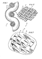
- the camouflage material 1 shown in Figures 1 and 2 is designed as a carrier fabric, which consists of crossing threads 2, 3. Plastic monofilaments are particularly suitable as the material for the threads 2, 3.
- the threads 2, 3 are surrounded by an electrically conductive layer 4, which has been applied by means of an impregnation technique.
- Their conductivity is brought about by electrically conductive pigments, such as graphite or carbon black.
- the graphite or carbon black particles are contained in an amount of 10 to 50% in a phenolic resin binder.
- the electrically conductive layer 4 appears black.
- this layer 4 is a synthetic, open cell Foam covering 5 applied, namely by immersing in an appropriate bath and then foaming and drying.
- the open cell structure of this foam covering increases the heat transfer area effective for air convection.
- the foam covering 5 can consist, for example, of polyurethane, polyLefin, polyvinyl chloride, polyester, polyether, polystyrene or polyacrylate. About 5 to 25% of metal pigments, for example copper, zinc, steel or preferably aluminum flakes, are embedded in the foam covering 5 in order to achieve a desired emission factor.
- the emission factor or emissivity should lie between 70 and 95% of the black body, while for winter camouflage an emissivity of 40 to 60X is sufficient.
- the emissivity should change continuously over the area within the aforementioned ranges in order to tear apart the representation in the thermal imaging device and to adapt it to the representation of the natural environment.
- the crossing threads 2, 3 run at a distance from each other, so that gaps 6 arise. This also contributes to the improvement of the heat transfer, since the heat transfer area for the convective air flow is thereby increased. This has the consequence that the camouflage material 1 is no longer heated as much by the sun's radiation as was the case with the known material.
- the distance a between two adjacent threads 2 it has been found to make the distance a between two adjacent threads 2 approximately half to one third as large as the thickness b of the Fadens 2 to design yourself.
- a corresponding treatment as is customary in the textile industry, can follow to fix the threads 2, 3.
- camouflage material 7 is shown in FIG. This camouflage material 7 is also woven from threads 8.
- the camouflage material 7 shown here is not air-permeable.
- the threads 8 and the gaps existing between them are surrounded or filled with an electrically conductive layer 9, which can consist of the same material as the electrically conductive layer 4 in the embodiment according to FIGS. 1 and 2.
- an electrically conductive layer 9 On both sides of the electrically conductive layer 9 are color layers 1 0, 11 applied with a color binder is transparent in the thermal infrared range, that is, for example, cyclo rubber, polyethylene or polypropylene. In this color binder, just like in the foam coating 5 in the embodiment according to FIGS.
- metal pigments are incorporated, with which the emissivity can be set in the desired range, with the target, the best possible adaptation to the emissivity of the surrounding nature to reach.
- color layers 1 0, 11 and foam coverings of the type can be applied as they are provided for the camouflage material 1 according to Figures 1 and 2, of course.
- the threads 8 of the camouflage material 7 can also be made of plastic, such as polyester, nylon, polyethylene, polypropylene or other filaments stand.
- the threads 8 of the camouflage material 7 - like the threads 2, 3 of the camouflage material 1 according to FIGS. 1 and 2 - can also be electrically conductive.
- the threads 2, 3, 8 are then produced in such a way that a thin aluminum foil with a thickness of 6 to 20 ⁇ m is laminated on both sides with a thin polyester film which can have a thickness of 6 to 20 ⁇ m in each case. This material is then cut into endless threads with a width of 0.2 to 0.5 mm.
- the threads can then partially or completely replace the plastic threads 2, 3, 8 in the camouflage materials 1, 7.
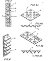
- the camouflage material 7 according to FIG. 3 has an increased heat transfer surface for the convection air flow passing by, its surface is additionally structured, as can be seen from FIGS. 4, 5 and 6.
- the camouflage material 7 ' is provided with cup-shaped recesses 12.
- pyramid-shaped depressions 13 are provided. Both types of depressions 12, 13 have been impressed by appropriately engraved calenders or rollers. The depressions 12, 13 not only have the task of increasing the heat transfer area, but are also intended to scatter the radar beams reflected by the respective electrically conductive layer 9 in a wide variety of directions.
- the camouflage material 7 ''' is folded in such a way that rib-shaped projections 14 are formed.
- These projections 14 have the same effect as the depressions 12, 13 in the camouflage materials 7 'and 7''in Figures 4 and 5.
- FIG. 7 shows a camouflage net 15 which consists of a support net 16 and colored patches 17 applied thereon in an irregular shape and at intervals.
- the spots 17 are cut out of the camouflage material 7 according to FIGS. 3 to 6.
- the support net 16 consists of the camouflage material 1 according to FIGS. 1 and 2.
- the support net 16 and / or the stains 17 - in the latter case before being applied to the support net 16 - can be provided with incisions.
- the electrically conductive paint can be applied by spraying, rolling or soaking. After drying the fabric to remove the solvent, it is immersed in a solution of 55% PVC and 45% PhthaLate plasticizer, which contains color and metallic pigments. After drying to form a foam covering, spots are clipped onto the fabric. These patches consist of a woven textile material of approximately 12 threads per cm, which is covered on both sides with an electrically conductive layer.
- Color layers are applied to this layer on both sides, which has a binder that is essentially transparent in the thermal infrared range and contains pigments reflecting heat radiation. whose colors also have a camouflaging effect in the visible area.
- the textile material is provided with embossed recesses, which have been embossed using an appropriate embossing calender.
- polyester fibers are used instead of polypropylene monofilaments.
- the electrically conductive layer contains aluminum particles and the foam covering consists of a pre-expanded acrylic dispersion.
- individual threads are woven into the textile material that are themselves electrically conductive, since they consist of plastic-laminated aluminum strips.
Landscapes
- Engineering & Computer Science (AREA)
- General Engineering & Computer Science (AREA)
- Aiming, Guidance, Guns With A Light Source, Armor, Camouflage, And Targets (AREA)
- Laminated Bodies (AREA)
- Orthopedics, Nursing, And Contraception (AREA)
Priority Applications (1)
| Application Number | Priority Date | Filing Date | Title |
|---|---|---|---|
| AT84106347T ATE29924T1 (de) | 1983-06-27 | 1984-05-30 | Tarnmaterial fuer die tarnung militaerischer ziele. |
Applications Claiming Priority (2)
| Application Number | Priority Date | Filing Date | Title |
|---|---|---|---|
| US06/507,969 US4465731A (en) | 1983-06-27 | 1983-06-27 | Universal camouflage for military objects |
| US507969 | 1983-06-27 |
Publications (3)
| Publication Number | Publication Date |
|---|---|
| EP0129744A2 true EP0129744A2 (fr) | 1985-01-02 |
| EP0129744A3 EP0129744A3 (en) | 1985-11-06 |
| EP0129744B1 EP0129744B1 (fr) | 1987-09-23 |
Family
ID=24020840
Family Applications (1)
| Application Number | Title | Priority Date | Filing Date |
|---|---|---|---|
| EP84106347A Expired EP0129744B1 (fr) | 1983-06-27 | 1984-05-30 | Matériau de camouflage pour dissimuler des cibles militaires |
Country Status (5)
| Country | Link |
|---|---|
| US (1) | US4465731A (fr) |
| EP (1) | EP0129744B1 (fr) |
| AT (1) | ATE29924T1 (fr) |
| CA (1) | CA1230969A (fr) |
| DE (1) | DE3466432D1 (fr) |
Cited By (5)
| Publication number | Priority date | Publication date | Assignee | Title |
|---|---|---|---|---|
| EP0311698A3 (fr) * | 1987-06-24 | 1989-11-08 | Fibrotex Ltd. | Filets de camouflage à trois dimensions |
| DE3840664A1 (de) * | 1988-12-02 | 1990-06-07 | Messerschmitt Boelkow Blohm | Multispektrales tarnnetz (radartarnnetz) |
| WO1991019950A1 (fr) * | 1990-06-14 | 1991-12-26 | Barracuda Technologies Ab | Camouflage visuel et thermique |
| DE29716362U1 (de) * | 1996-09-14 | 1998-01-08 | C.F. Ploucquet GmbH & Co, 89522 Heidenheim | Wärmetarnplane |
| RU2546470C1 (ru) * | 2014-03-03 | 2015-04-10 | Сергей Александрович Филин | Маскировочная сеть |
Families Citing this family (22)
| Publication number | Priority date | Publication date | Assignee | Title |
|---|---|---|---|---|
| US4529633A (en) * | 1983-01-14 | 1985-07-16 | Diab-Barracuda Ab | Thermal camouflage |
| SE457115B (sv) * | 1983-03-25 | 1988-11-28 | Diab Barracuda Ab | Termisk och optisk kamouflage |
| US4621012A (en) * | 1984-11-15 | 1986-11-04 | Gunter Pusch | Camouflage net having a semiconductive layer |
| US4728677A (en) * | 1986-05-30 | 1988-03-01 | The B. F. Goodrich Company | Weatherable vinyl polymer compositions |
| US4766610A (en) * | 1987-01-22 | 1988-08-30 | Varo, Inc. | Replaceable cushion liner for military headgear |
| US4741054A (en) * | 1987-01-22 | 1988-05-03 | Varo, Inc. | Chin cup for use with military headgear |
| JPS63159697U (fr) * | 1987-04-08 | 1988-10-19 | ||
| JPS63159696U (fr) * | 1987-04-08 | 1988-10-19 | ||
| JPS63159695U (fr) * | 1987-04-08 | 1988-10-19 | ||
| ATE117624T1 (de) * | 1988-02-19 | 1995-02-15 | Wilkie J & D Ltd | Thermischer tarnungsstoff. |
| DE3810121A1 (de) * | 1988-03-25 | 1989-10-05 | Hornschuch Ag K | Tarnnetz und verfahren zu seiner herstellung |
| JPH0689998B2 (ja) * | 1988-08-11 | 1994-11-14 | 東レ株式会社 | 遠赤外線偽装材用補助材料 |
| GB2237862B (en) * | 1989-10-30 | 1994-07-06 | Colebrand Ltd | Absorbers |
| US5955175A (en) * | 1996-09-20 | 1999-09-21 | W. L. Gore & Associates, Inc. | Infra-red reflective coverings |
| SE513643C2 (sv) | 1998-09-07 | 2000-10-16 | Barracuda Tech Ab | Maskeringsmaterial med optisk maskeringsverkan, med tredimensionell ytstruktur |
| AU775033B2 (en) * | 1999-10-01 | 2004-07-15 | John L. Larue | Camouflaged structure and method of camouflaging a structure against a background having a generally uniform composition |
| DE10240802A1 (de) * | 2002-08-30 | 2004-04-15 | W.L. Gore & Associates Gmbh | IR reflektierendes Material |
| KR100775127B1 (ko) * | 2005-12-14 | 2007-11-08 | 삼양화학공업주식회사 | 무전해 도금 섬유를 이용한 위장직물 |
| US8075567B2 (en) * | 2007-03-22 | 2011-12-13 | Anchor Products Company | Surgical tissue retrieval instrument |
| WO2014120867A1 (fr) * | 2013-01-30 | 2014-08-07 | Miller Stephen D | Tissu à protubérance souple et articles fabriqués à partir de celui-ci |
| CN106364106B (zh) * | 2016-08-17 | 2019-05-31 | 浙江盛发纺织印染有限公司 | 一种反侦察装备专用面料 |
| USD820604S1 (en) * | 2017-10-20 | 2018-06-19 | Nike, Inc. | Garment |
Family Cites Families (15)
| Publication number | Priority date | Publication date | Assignee | Title |
|---|---|---|---|---|
| DE1034070B (de) * | 1952-11-13 | 1958-07-10 | Oberndorfer Gardinen Und Spitz | Engmaschiges Tarnnetz |
| DE1056508B (de) * | 1955-05-26 | 1959-04-30 | Ekman & Brundin | Verfahren zum Herstellen von Tarnnetzen |
| BE548618A (fr) * | 1955-06-13 | |||
| DE1035529B (de) * | 1957-01-18 | 1958-07-31 | Rudolf Baumann G M B H | Tarnnetz |
| FR1233225A (fr) * | 1959-07-20 | 1960-10-12 | Albert Markmann & Co | Tissu ininflammable, notamment pour décoration et camouflage |
| DE1916326A1 (de) * | 1968-04-01 | 1969-10-30 | Barracudaverken Ab | Tarnungsmittel zum Verhindern oder Hemmen der Entdeckung durch Radarerkundung |
| GB1314624A (en) * | 1971-04-06 | 1973-04-26 | Barracudaverken Ab | Radar camouflage |
| DE2310088A1 (de) * | 1973-03-01 | 1974-09-19 | Ogus Netze & Wirkwaren | Tarnnetz |
| US3977927A (en) * | 1975-01-13 | 1976-08-31 | Brunswick Corporation | Machine and method for making camouflage nets |
| CA1070004A (fr) * | 1975-04-16 | 1980-01-15 | Barracudaverken Ab | Materiel de camouflage |
| SE420236B (sv) * | 1975-05-13 | 1981-09-21 | Barracudaverken Ab | Radarkamouflerande kamouflageduk med stodvev |
| FR2334080A1 (fr) * | 1975-06-26 | 1977-07-01 | Barracudaverken Ab | Feuille de camouflage souple a revetement renforce |
| US4142015A (en) * | 1977-05-04 | 1979-02-27 | The United States Of America As Represented By The Secretary Of The Army | Thermal camouflage |
| DE2750919C1 (de) * | 1977-11-15 | 1984-03-01 | Pusch, Günter, Dr.-Ing., 6903 Neckargemünd | Breitbandige Tarnung militaerischer Ziele |
| FR2442422A1 (fr) * | 1978-11-23 | 1980-06-20 | Coureur Raymond | Ecran absorbant et/ou reflechissant les radiations electromagnetiques |
-
1983
- 1983-06-27 US US06/507,969 patent/US4465731A/en not_active Expired - Lifetime
-
1984
- 1984-05-30 DE DE8484106347T patent/DE3466432D1/de not_active Expired
- 1984-05-30 AT AT84106347T patent/ATE29924T1/de not_active IP Right Cessation
- 1984-05-30 EP EP84106347A patent/EP0129744B1/fr not_active Expired
- 1984-06-13 CA CA000456525A patent/CA1230969A/fr not_active Expired
Cited By (5)
| Publication number | Priority date | Publication date | Assignee | Title |
|---|---|---|---|---|
| EP0311698A3 (fr) * | 1987-06-24 | 1989-11-08 | Fibrotex Ltd. | Filets de camouflage à trois dimensions |
| DE3840664A1 (de) * | 1988-12-02 | 1990-06-07 | Messerschmitt Boelkow Blohm | Multispektrales tarnnetz (radartarnnetz) |
| WO1991019950A1 (fr) * | 1990-06-14 | 1991-12-26 | Barracuda Technologies Ab | Camouflage visuel et thermique |
| DE29716362U1 (de) * | 1996-09-14 | 1998-01-08 | C.F. Ploucquet GmbH & Co, 89522 Heidenheim | Wärmetarnplane |
| RU2546470C1 (ru) * | 2014-03-03 | 2015-04-10 | Сергей Александрович Филин | Маскировочная сеть |
Also Published As
| Publication number | Publication date |
|---|---|
| ATE29924T1 (de) | 1987-10-15 |
| DE3466432D1 (en) | 1987-10-29 |
| US4465731A (en) | 1984-08-14 |
| EP0129744B1 (fr) | 1987-09-23 |
| EP0129744A3 (en) | 1985-11-06 |
| CA1230969A (fr) | 1988-01-05 |
Similar Documents
| Publication | Publication Date | Title |
|---|---|---|
| EP0129744B1 (fr) | Matériau de camouflage pour dissimuler des cibles militaires | |
| DE4023287C2 (de) | Tarnnetz | |
| DE2929537C2 (fr) | ||
| DE2601062C3 (de) | Flexible Bahn mit radarüberwindenden Eigenschaften | |
| CH667524A5 (de) | Tarnmaterial mit thermischer und optischer tarnwirkung. | |
| DE69703118T2 (de) | Infrarot reflektierende abdeckungen | |
| DE2620093A1 (de) | Verstaerkungseinlage fuer tarnmaterial und tarntuch fuer funkmesstarnung (radartarnung) | |
| DD150917A5 (de) | Schallabsorbierendes bauelement aus kunststoff-folie | |
| DE2709091A1 (de) | Verfahren und vorrichtung zur rueckgewinnung von von einer waermequelle abgestrahlter verlustwaerme | |
| DE69706243T2 (de) | Persönliche Schutzauskleidung für die Infanterie | |
| DD239513A5 (de) | Gewaechshausschattiervorrichtung | |
| DE1279131B (de) | Radar- und Infrarot-Tarnnetz | |
| DE2833579A1 (de) | Vorhangsgewebe mit offenen maschen | |
| DE3135586A1 (de) | Tarnvorrichtung an fahrzeugen gegen erkennung | |
| EP0912875B1 (fr) | Structure de camouflage | |
| EP0246342B1 (fr) | Matériaux de revêtement à émissivité réduite dans le domaine spectral du rayonnement thermique | |
| WO2008034771A1 (fr) | Dispositif pour le camouflage d'objets et/ou de personnes | |
| DE2943430C2 (de) | Tarnnetz | |
| DE20004682U1 (de) | Tarnunterstand mit einer faltbaren selbsttragenden Unterkonstruktion | |
| DE4444104C1 (de) | Wärmeschutz mit passiver Solarenergienutzung | |
| DE3444595C2 (fr) | ||
| DE2619512A1 (de) | Tarntuch oder -platte mit lochmuster | |
| EP2167009B1 (fr) | Chambre solaire, en particulier sauna solaire ou serre | |
| DE19816707C2 (de) | Verfahren zur Herstellung eines breitbandigen Tarnmaterials | |
| EP3541180A1 (fr) | Élément herbicide multicouche et procédé d'utilisation d'un tel élément herbicide |
Legal Events
| Date | Code | Title | Description |
|---|---|---|---|
| PUAI | Public reference made under article 153(3) epc to a published international application that has entered the european phase |
Free format text: ORIGINAL CODE: 0009012 |
|
| AK | Designated contracting states |
Designated state(s): AT CH DE FR GB IT LI NL SE |
|
| PUAL | Search report despatched |
Free format text: ORIGINAL CODE: 0009013 |
|
| AK | Designated contracting states |
Designated state(s): AT CH DE FR GB IT LI NL SE |
|
| 17P | Request for examination filed |
Effective date: 19851128 |
|
| 17Q | First examination report despatched |
Effective date: 19870311 |
|
| GRAA | (expected) grant |
Free format text: ORIGINAL CODE: 0009210 |
|
| AK | Designated contracting states |
Kind code of ref document: B1 Designated state(s): AT CH DE FR GB IT LI NL SE |
|
| REF | Corresponds to: |
Ref document number: 29924 Country of ref document: AT Date of ref document: 19871015 Kind code of ref document: T |
|
| GBT | Gb: translation of ep patent filed (gb section 77(6)(a)/1977) | ||
| REF | Corresponds to: |
Ref document number: 3466432 Country of ref document: DE Date of ref document: 19871029 |
|
| ITF | It: translation for a ep patent filed | ||
| ET | Fr: translation filed | ||
| PLBI | Opposition filed |
Free format text: ORIGINAL CODE: 0009260 |
|
| 26 | Opposition filed |
Opponent name: OGUS NETZE- UND WIRKWAREN GMBH Effective date: 19880622 |
|
| NLR1 | Nl: opposition has been filed with the epo |
Opponent name: OGUS NETZE- UND WIRKWAREN GMBH |
|
| PG25 | Lapsed in a contracting state [announced via postgrant information from national office to epo] |
Ref country code: GB Effective date: 19890530 Ref country code: AT Effective date: 19890530 |
|
| PG25 | Lapsed in a contracting state [announced via postgrant information from national office to epo] |
Ref country code: SE Effective date: 19890531 Ref country code: LI Free format text: LAPSE BECAUSE OF NON-PAYMENT OF DUE FEES Effective date: 19890531 Ref country code: CH Free format text: LAPSE BECAUSE OF NON-PAYMENT OF DUE FEES Effective date: 19890531 |
|
| PG25 | Lapsed in a contracting state [announced via postgrant information from national office to epo] |
Ref country code: NL Effective date: 19891201 |
|
| NLV4 | Nl: lapsed or anulled due to non-payment of the annual fee | ||
| GBPC | Gb: european patent ceased through non-payment of renewal fee | ||
| PG25 | Lapsed in a contracting state [announced via postgrant information from national office to epo] |
Ref country code: FR Free format text: LAPSE BECAUSE OF NON-PAYMENT OF DUE FEES Effective date: 19900131 |
|
| REG | Reference to a national code |
Ref country code: CH Ref legal event code: PL |
|
| PG25 | Lapsed in a contracting state [announced via postgrant information from national office to epo] |
Ref country code: DE Effective date: 19900201 |
|
| REG | Reference to a national code |
Ref country code: FR Ref legal event code: ST |
|
| RDAG | Patent revoked |
Free format text: ORIGINAL CODE: 0009271 |
|
| STAA | Information on the status of an ep patent application or granted ep patent |
Free format text: STATUS: PATENT REVOKED |
|
| 27W | Patent revoked |
Effective date: 19910118 |
|
| GBPR | Gb: patent revoked under art. 102 of the ep convention designating the uk as contracting state | ||
| EUG | Se: european patent has lapsed |
Ref document number: 84106347.2 Effective date: 19891206 |
|
| PLAB | Opposition data, opponent's data or that of the opponent's representative modified |
Free format text: ORIGINAL CODE: 0009299OPPO |