EP0129780A2 - Entkopplungsmembran für Zweikammer-Motorlager - Google Patents
Entkopplungsmembran für Zweikammer-Motorlager Download PDFInfo
- Publication number
- EP0129780A2 EP0129780A2 EP84106776A EP84106776A EP0129780A2 EP 0129780 A2 EP0129780 A2 EP 0129780A2 EP 84106776 A EP84106776 A EP 84106776A EP 84106776 A EP84106776 A EP 84106776A EP 0129780 A2 EP0129780 A2 EP 0129780A2
- Authority
- EP
- European Patent Office
- Prior art keywords
- membrane
- chamber
- rubber body
- annular
- membrane according
- Prior art date
- Legal status (The legal status is an assumption and is not a legal conclusion. Google has not performed a legal analysis and makes no representation as to the accuracy of the status listed.)
- Granted
Links
- 239000012528 membrane Substances 0.000 title claims abstract description 26
- 239000006096 absorbing agent Substances 0.000 claims abstract description 17
- 238000013016 damping Methods 0.000 claims abstract description 3
- 239000007788 liquid Substances 0.000 claims abstract description 3
- 239000002184 metal Substances 0.000 claims description 2
- 239000013013 elastic material Substances 0.000 description 2
- 239000000463 material Substances 0.000 description 2
- 239000007787 solid Substances 0.000 description 2
- 239000013536 elastomeric material Substances 0.000 description 1
- 230000005284 excitation Effects 0.000 description 1
- 239000012530 fluid Substances 0.000 description 1
- 238000002955 isolation Methods 0.000 description 1
- 230000003534 oscillatory effect Effects 0.000 description 1
Images
Classifications
-
- F—MECHANICAL ENGINEERING; LIGHTING; HEATING; WEAPONS; BLASTING
- F16—ENGINEERING ELEMENTS AND UNITS; GENERAL MEASURES FOR PRODUCING AND MAINTAINING EFFECTIVE FUNCTIONING OF MACHINES OR INSTALLATIONS; THERMAL INSULATION IN GENERAL
- F16F—SPRINGS; SHOCK-ABSORBERS; MEANS FOR DAMPING VIBRATION
- F16F13/00—Units comprising springs of the non-fluid type as well as vibration-dampers, shock-absorbers, or fluid springs
- F16F13/04—Units comprising springs of the non-fluid type as well as vibration-dampers, shock-absorbers, or fluid springs comprising both a plastics spring and a damper, e.g. a friction damper
- F16F13/06—Units comprising springs of the non-fluid type as well as vibration-dampers, shock-absorbers, or fluid springs comprising both a plastics spring and a damper, e.g. a friction damper the damper being a fluid damper, e.g. the plastics spring not forming a part of the wall of the fluid chamber of the damper
- F16F13/22—Units comprising springs of the non-fluid type as well as vibration-dampers, shock-absorbers, or fluid springs comprising both a plastics spring and a damper, e.g. a friction damper the damper being a fluid damper, e.g. the plastics spring not forming a part of the wall of the fluid chamber of the damper characterised by comprising also a dynamic damper
Definitions
- the invention relates to a decoupling membrane for two-chamber engine mounts with hydraulic damping, in particular for motor vehicles, consisting of an annular rubber body and a central, metallic circular disk as absorber mass, which is firmly bonded to one another and is liquid-tightly fastened in the upper region of the upper liquid chamber to separate a membrane chamber .
- Such a decoupling membrane - but made entirely of elastomeric material - is known from DE-OS 30 24 091.
- a decoupling membrane which, according to the subject matter, consists of a very soft circular rubber body and a central metallic absorber mass.
- a decoupling membrane is intended to ensure that a decoupling of small amplitudes of the order of magnitude of approximately 0.1 mm is reliably ensured in a hydraulically damped motor bearing in order to ensure optimal isolation of both the acoustic behavior and the vibrations introduced.
- the annular rubber body in the previously customary design of the annular rubber body as a very soft, flat ring plate or as a corrugated ring washer, however, there is a risk that the metallic absorber mass strikes the upper end wall of the bearing with larger deflections and thus generates undesirable noises.
- the vibration path of the absorber mass occurring with the above training is difficult to grasp or precisely define.
- the present invention is therefore based on the object of providing a decoupling membrane which practically has an integrated path limitation for the vertical oscillatory movements of the absorber mass, in order to be able to achieve and set a precisely defined maximum deflection.
- the circular rubber body has on its top and bottom two concentric ring grooves, each conically inclined towards the surface, which extend approximately to the horizontal central plane of the membrane.
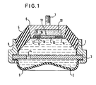
- the two-chamber engine mount consists essentially of an upper, engine-side chamber 1 and a lower chamber 2, which are separated from each other with a hydraulic fluid *) and by an elastically mounted intermediate plate 3 with a throttle opening 4 .
- the upper chamber 1 is formed by a thick-walled, hollow-conical chamber wall 5 made of rubber-elastic material, which is closed on the upper end face by the motor mounting plate 6 with an attached threaded bolt 7 and is adhesively connected on the lower outer circumference to the annular abutment 8.
- the lower chamber 2 is formed by an example cup-shaped chamber wall 9 made of rubber-elastic material.
- a cylindrical cavity 10 is inserted as a membrane chamber, which * ) fills
- This decoupling membrane 11 consists of an annular rubber body 12 and a central metallic absorber mass 13, which are firmly adhered to each other. On the outer circumference, the rubber body 12 is enclosed by a metal ring 14 for mounting and fixing in the engine mounting plate 6.
- the rubber body 12 now has two conically inclined annular grooves 15 and 16 on the upper side and two annular grooves 17 and 18 arranged symmetrically to the lower side.
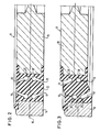
- the two outer grooves 15 and 17, which are symmetrically opposite each other to the central plane 19, are at an angle of approximately 20 ° inwards and the two inner ones Grooves 16 and 18 inclined outwards at the same angle.
- the inclination of these grooves 15 to 18 can advantageously be in the range 15-30 0th
- the annular grooves 15 to 18 are each widened to a circular cross section 20 at the base of the groove in order to ensure greater mobility in the vertical direction.
- the ratio of height to width of these ring grooves should be approximately 3: 1 to 4: 1, which also allows the size of the permissible deflection to be determined.
Landscapes
- Engineering & Computer Science (AREA)
- General Engineering & Computer Science (AREA)
- Mechanical Engineering (AREA)
- Combined Devices Of Dampers And Springs (AREA)
- Arrangement Or Mounting Of Propulsion Units For Vehicles (AREA)
Abstract
Description
- Die Erfindung betrifft eine Entkopplungsmembran für Zweikammer-Motorlager mit hydraulischer Dämpfung, insbesondere für Kraftfahrzeuge, bestehend aus einem kreisringförmigen Gummikörper und einer zentralen,metallischen Kreisscheibe als Tilgermasse, die fest haftend miteinander verbunden und im oberen Bereich der oberen Flüssigkeitskammer zur Abtrennung einer Membrankammer flüssigkeitsdicht befestigt ist.
- Eine derartige Entkopplungsmembran - jedoch durchgehend aus elastomerem Material - ist aus der DE-OS 30 24 091 bekannt.
- In einem älteren Vorschlag (P 32 44 295.5-12) ist eine Entkopplungsmembran beschrieben, die entsprechend dem vorliegenden Gegenstand aus einem sehr weichen kreisringförmigen Gummikörper und einer zentralen metallischen Tilgermasse besteht. Mit einer derartigen Entkopplungsmembran soll erreicht werden, daß in einem hydraulisch gedämpften Motorlager eine Entkoppelung von kleinen Amplituden in der Größenordnung von etwa 0,1 mm sicher gewährleistet ist, um eine optimale Isolierung sowohl des akustischen Verhaltens als auch der eingeleiteten Schwingungen sicherzustellen. Bei der bisher üblichen Ausführung des kreisringförmigen Gummikörpers als sehr weiche, ebene Ringplatte oder als gewellte Ringscheibe besteht jedoch die Gefahr, daß die metallische Tilgermasse bei größeren Auslenkungen gegen die obere Stirnwand des Lagers schlägt und damit unerwünschte Geräusche erzeugt. Darüber hinaus ist der auftretende Schwingungsweg der Tilgermasse bei der vorstehenden Ausbildung nur schwer zu erfassen oder genau zu definieren.
- Der vorliegenden Erfindung liegt daher die Aufgabe zugrunde eine Entkopplungsmembran zu schaffen, die praktisch eine integrierte Wegbegrenzung für die vertikalen Schwingungsbewegungen der Tilgermasse aufweist, um somit eine genau definierte maximale Auslenkung zu erreichen und einstellen zu können.
- Zur Lösung dieser Aufgabe ist erfindungsgemäß vorgesehen, daß der kreisringförmige Gummikörper auf seiner Ober-und Unterseite jeweils zwei konzentrische, jeweils zur Oberfläche hin einander konisch zugeneigte Ringnuten aufweist, die sich angenähert bis zur horizontalen Mittelebene der Membran erstrecken.
- Durch die Anordnung derartiger konischer Ringnuten ist zunächst für eine vorgebbare Wegstrecke eine relativ freie vertikale Beweglichkeit der Tilgermasse ermöglicht, während anschließend die Nutflanken zweier einander diametral gegenüberliegender Nuten auf Ober- und Unterseite der Membran aufeinandertreffen und damit - abgesehen von der bleibenden Elastizität des massiven Gummikörpers - einer weiteren vertikalen Bewegung der Tilgermasse entgegenwirken.
- Zweckmäßige Ausgestaltungen der Erfindung sind in den Unteransprüchen aufgeführt.
- Anhand einer schematischen Zeichnung sind Aufbau und Wirkungsweise eines Ausführungsbeispiels nach der Erfindung näher erläutert. Dabei zeigen:
- Fig. 1 einen Querschnitt durch die Gesamtanordnung eines Zweikammer-Motorlagers,
- Fig. 2 einen Querschnitt durch eine Hälfte der Entkopplungsmembran in vergrößertem Maßstab und
- Fig. 3 einen Querschnitt entsprechend Fig. 2 nach Auslenkung der Tilgermasse in ihre obere Endlage.
- Wie aus Fig. 1 zu ersehen ist, besteht das Zweikammer-Motorlager im wesentlichen aus einer oberen,motorseitigen Kammer 1 und einer unteren Kammer 2, die mit einer hydraulischen Flüssigkeit *) und durch eine elastisch gelagerte Zwischenplatte 3 mit einer Drosselöffnung 4 voneinander getrennt sind. Die obere Kammer 1 wird von einer starkwandigen, hohlkegelförmigen Kammerwandung 5 aus gummielastischem Material gebildet, die an der oberen Stirnseite von der Motorlagerplatte 6 mit einem aufgesetzten Gewindebolzen 7 abgeschlossen und am unteren Außenumfang mit dem ringförmigen Widerlager 8 haftend verbunden ist. Die untere Kammer 2 wird von einer beispielsweisen tassenförmigen Kammerwandung 9 aus ebenfalls gummielastischem Material gebildet.
- Auf der Unterseite der Motorlagerplatte 6 ist ein zylindrischer Hohlraum 10 als Membrankammer eingelassen, der *)gefüllt
- zur oberen Kammer 1 durch eine Entkopplungsmembran 11 abgeschlossen ist. Diese Entkopplungsmembran 11 besteht aus einem kreisringförmigen Gummikörper 12 und einer zentralen metallischen Tilgermasse 13, die fest haftend miteinander verbunden sind. Am Außenumfang ist der Gummikörper 12 von einem Metallring 14 zur Halterung und Festlegung in der Motor-Lagerplatte 6 umschlossen.
- Erfindungsgemäß weist nunmehr der Gummikörper 12 auf der Oberseite zwei konisch zueinander geneigte Ringnuten 15 und 16 und auf der Unterseite zwei symmetrisch dazu angeordnete Ringnuten 17 und 18 auf.
- Wie im einzelnen aus dem Querschnitt im vergrößerten Maßstab durch die linke Hälfte der Entkopplungsmembran 11 nach Fig. 2 zu ersehen ist, sind die beiden zur Mittelebene 19 einander symmetrisch gegenüberliegenden äußeren Nuten 15 und 17 im Winkel von etwa 20° nach innen und die beiden innenliegenden Nuten 16 und 18 im gleichen Winkel nach außen geneigt. Je nach gewünschter zulässiger Auslenkung der Tilgermasse 13 kann die Neigung dieser Nuten 15 bis 18 zweckmäßigerweise im Bereich von 15 bis 300 liegen. Die Ringnuten 15 bis 18 sind dabei jeweils am Nutgrund auf kreisförmigen Querschnitt 20 erweitert, um eine größere Beweglichkeit in vertikaler Richtung zu gewährleisten. Das Verhältnis von Höhe zu Breite dieser Ringnuten sollte etwa 3 : 1 bis 4 : 1 betragen, wodurch ebenfalls die Größe der zulässigen Auslenkung festgelegt werden kann.
- Die Funktionsweise dieser Ringnuten sei nunmehr in Fig. 3 erläutert. Bei Anregung der schwingend gelagerten Tilgermasse 13 durch die Erregerfrequenz gerät diese in Bewegung und bewirkt dadurch ein Verkanten des Gummikörpers 12. Bei der in der Figur dargestellten Bewegung der Tilgermasse 13 schließen sich nach einer vorgegebenen Wegstrecke die einander diagonal gegenüberliegenden konischen Ringspalte 15 und 18 , wobei deren Flanken weich anstoßen. Durch dieses Schließen der Nuten und dem dadurch bedingten Aneinanderstoßen benachbarter Materialbereiche des Gummikörpers ergibt sich somit wegen der relativ geringen auf die Tilgermasse 13 einwirkenden Kräfte eine eindeutige Begrenzung des vertikalen Weges der Tilgermasse 13. Damit kann also eine definierte Wegbegrenzung erreicht und ein Anschlagen der Tilgermasse 13 an die obere Stirnwand der Membrankammer verhindert werden.
- In entsprechender Weise würden sich bei einer Bewegung der Tilgermasse nach unten die jetzt noch geöffneten Ringnuten 16 und 17 verschließen und damit eine definierte Wegbegrenzung nach unten bewirken.
- Für eine genau definierte Wegbegrenzung, d.h. zu Minimierung einer möglichen Restelastizität des massiven Gummikörpers bei geschlossenen Nuten kann jetzt auch eine Gummiqualität höherer Shore-Härte verwendet werden, da die freie Beweglichkeit der Tilgermasse 13 wegen der relativ tiefen Nuteinschnitte nur noch durch die Stärke des zwischen einander gegenüberliegenden Nutgrunden 20 vorhandenen Materialbereich 21 bestimmt ist.
Claims (6)
Applications Claiming Priority (2)
| Application Number | Priority Date | Filing Date | Title |
|---|---|---|---|
| DE3323178A DE3323178C2 (de) | 1983-06-28 | 1983-06-28 | Entkopplungsmembran für ein Zweikammer-Motorlager |
| DE3323178 | 1983-06-28 |
Publications (3)
| Publication Number | Publication Date |
|---|---|
| EP0129780A2 true EP0129780A2 (de) | 1985-01-02 |
| EP0129780A3 EP0129780A3 (en) | 1986-07-09 |
| EP0129780B1 EP0129780B1 (de) | 1988-03-09 |
Family
ID=6202541
Family Applications (1)
| Application Number | Title | Priority Date | Filing Date |
|---|---|---|---|
| EP84106776A Expired EP0129780B1 (de) | 1983-06-28 | 1984-06-14 | Entkopplungsmembran für Zweikammer-Motorlager |
Country Status (6)
| Country | Link |
|---|---|
| US (1) | US4589638A (de) |
| EP (1) | EP0129780B1 (de) |
| JP (1) | JPS6034545A (de) |
| BR (1) | BR8403148A (de) |
| DE (2) | DE3323178C2 (de) |
| ES (1) | ES280265Y (de) |
Cited By (4)
| Publication number | Priority date | Publication date | Assignee | Title |
|---|---|---|---|---|
| EP0189510A1 (de) * | 1985-01-15 | 1986-08-06 | Firma Carl Freudenberg | Motorlager |
| EP0189509A1 (de) * | 1985-01-15 | 1986-08-06 | Firma Carl Freudenberg | Motorlager |
| EP0212143A3 (de) * | 1985-08-06 | 1989-01-04 | Continental Aktiengesellschaft | Membran |
| EP0750131A1 (de) * | 1995-06-21 | 1996-12-27 | Hutchinson | Elastisches Lager für schwingende Masse |
Families Citing this family (2)
| Publication number | Priority date | Publication date | Assignee | Title |
|---|---|---|---|---|
| IT1237779B (it) * | 1989-11-20 | 1993-06-17 | Pirelli Sistemi Antivibranti | Supporto motore. |
| GB2241042B (en) * | 1990-02-16 | 1994-01-05 | Pioneer Electronic Corp | Damper filled with oil |
Family Cites Families (21)
| Publication number | Priority date | Publication date | Assignee | Title |
|---|---|---|---|---|
| BE524185A (de) * | 1952-12-11 | |||
| FR1120259A (fr) * | 1955-01-22 | 1956-07-03 | Dispositif amortisseur à bloc élastiquement déformable | |
| GB825668A (en) * | 1957-04-30 | 1959-12-16 | Wright Howard Clayton Ltd | Improved resilient mounting |
| FR1251719A (fr) * | 1959-03-25 | 1961-01-20 | Gomma Antivibranti Applic | Support élastique antivibrant pour organes de machines, particulièrement pour arbres de transmission |
| FR1281685A (fr) * | 1961-02-22 | 1962-01-12 | Caoutchouc Et Plastiques | Isolateur anti-vibrations |
| DE1214479B (de) * | 1964-10-21 | 1966-04-14 | Continental Gummi Werke Ag | Federkoerper aus gummielastischem Werkstoff |
| DE2652501A1 (de) * | 1976-11-18 | 1978-05-24 | Phoenix Gummiwerke Ag | Elastisches lager |
| JPS53117704A (en) * | 1977-03-23 | 1978-10-14 | Boge Gmbh | Motor bearing device resilient like rubber |
| DE2802896C2 (de) * | 1978-01-24 | 1982-09-23 | Audi Nsu Auto Union Ag, 7107 Neckarsulm | Gummilager mit hydraulischer Dämpfung |
| EP0006819B1 (de) * | 1978-07-03 | 1984-06-27 | Automobiles Peugeot | Aufhängungsvorrichtung insbesondere für Fahrzeugmotor |
| IT1110771B (it) * | 1979-02-09 | 1986-01-06 | Gomma Antivibranti Applic | Sopporto ammortizzante per la sospensione di un corpo oscillante ad una struttura di sopporto,particolarmente per la sospensione del motore al telaio di un autoveicolo |
| DE2905090C2 (de) * | 1979-02-10 | 1987-11-12 | Fa. Carl Freudenberg, 6940 Weinheim | Gummilager mit hydraulischer Dämpfung |
| JPS597852B2 (ja) * | 1979-10-31 | 1984-02-21 | 豊田合成株式会社 | 液封入防振装置 |
| DE2947018C2 (de) * | 1979-11-22 | 1982-05-27 | Audi Nsu Auto Union Ag, 7107 Neckarsulm | Elastisches Lager, insbesondere zur Lagerung einer Brennkraftmaschine in einem Kraftfahrzeug |
| DE3024089C3 (de) * | 1980-06-27 | 1992-10-08 | Boge Gmbh | Hydraulisch dämpfendes lager |
| DE3024091C2 (de) * | 1980-06-27 | 1983-02-17 | Boge Gmbh, 5208 Eitorf | Hydraulisch dämpfendes Einkammerlager |
| US4352487A (en) * | 1980-11-18 | 1982-10-05 | Gould Inc. | Viscous spring damper |
| FR2496208B1 (fr) * | 1980-12-17 | 1985-11-29 | Peugeot | Articulation elastique a flexibilite variable, notamment pour le montage d'un amortisseur telescopique de suspension sur un vehicule automobile |
| FR2500555B1 (fr) * | 1981-02-20 | 1986-09-05 | Hutchinson Mapa | Perfectionnements apportes aux amortisseurs hydrauliques |
| DE3125040C2 (de) * | 1981-06-26 | 1985-09-12 | Mair, Christian, 8077 Agelsberg | Elastisches Lager insbesondere zur Lagerung von Maschinen oder Maschinenteilen |
| DE3244295A1 (de) * | 1982-11-30 | 1984-05-30 | Metzeler Kautschuk GmbH, 8000 München | Zweikammer-motorlager mit hydraulischer daempfung |
-
1983
- 1983-06-28 DE DE3323178A patent/DE3323178C2/de not_active Expired
-
1984
- 1984-06-14 EP EP84106776A patent/EP0129780B1/de not_active Expired
- 1984-06-14 DE DE8484106776T patent/DE3469789D1/de not_active Expired
- 1984-06-27 BR BR8403148A patent/BR8403148A/pt unknown
- 1984-06-28 JP JP59134057A patent/JPS6034545A/ja active Granted
- 1984-06-28 ES ES1984280265U patent/ES280265Y/es not_active Expired
- 1984-06-28 US US06/625,460 patent/US4589638A/en not_active Expired - Fee Related
Cited By (4)
| Publication number | Priority date | Publication date | Assignee | Title |
|---|---|---|---|---|
| EP0189510A1 (de) * | 1985-01-15 | 1986-08-06 | Firma Carl Freudenberg | Motorlager |
| EP0189509A1 (de) * | 1985-01-15 | 1986-08-06 | Firma Carl Freudenberg | Motorlager |
| EP0212143A3 (de) * | 1985-08-06 | 1989-01-04 | Continental Aktiengesellschaft | Membran |
| EP0750131A1 (de) * | 1995-06-21 | 1996-12-27 | Hutchinson | Elastisches Lager für schwingende Masse |
Also Published As
| Publication number | Publication date |
|---|---|
| DE3323178A1 (de) | 1985-01-17 |
| EP0129780B1 (de) | 1988-03-09 |
| BR8403148A (pt) | 1985-06-11 |
| US4589638A (en) | 1986-05-20 |
| ES280265Y (es) | 1985-07-16 |
| DE3323178C2 (de) | 1986-11-06 |
| EP0129780A3 (en) | 1986-07-09 |
| ES280265U (es) | 1985-01-16 |
| JPS6410700B2 (de) | 1989-02-22 |
| JPS6034545A (ja) | 1985-02-22 |
| DE3469789D1 (en) | 1988-04-14 |
Similar Documents
| Publication | Publication Date | Title |
|---|---|---|
| EP0209883B1 (de) | Zweikammer-Motorlager mit hydraulischer Dämpfung | |
| DE2802896C2 (de) | Gummilager mit hydraulischer Dämpfung | |
| DE3808996C2 (de) | ||
| EP0044545B1 (de) | Zweikammer-Motorlager mit hydraulischer Dämpfung | |
| DE68908023T2 (de) | Mit Flüssigkeit gefüllter Schwingungsdämpfer. | |
| DE3443029C2 (de) | Elastisches Motorlager | |
| DE3419437C2 (de) | ||
| EP0110195B1 (de) | Zweikammer-Motorlager mit hydraulischer Dämpfung | |
| DE2937052A1 (de) | Daempfungslager zur aufhaengung eines schwingenden koerpers an einer traegerstruktur, insbesondere zur aufhaengung des motors im rahmen eines kraftfahrzeuges | |
| EP0110197A1 (de) | Zweikammer-Motorlager mit hydraulischer Dämpfung | |
| DE4111318A1 (de) | Hydraulische, buchsenfoermige daempfungsvorrichtung | |
| EP0042908A2 (de) | Motorlager für Lastkraftwagen, Omnibusse oder dergleichen Nutzfahrzeuge | |
| EP0534124A1 (de) | Elastisches Motorlager | |
| EP0231898B1 (de) | Hydraulisch dämpfendes Lager | |
| EP0332901A2 (de) | Elastische und hydraulisch dämpfende Buchse | |
| DE2929084C2 (de) | Schwingungsdämpfendes Lager | |
| EP0351737B1 (de) | Hydraulisch dämpfendes Motorlager | |
| EP0129780B1 (de) | Entkopplungsmembran für Zweikammer-Motorlager | |
| DE3920153A1 (de) | Motor-traeger mit fluidfuellung | |
| DE3024091A1 (de) | Hydraulisch daempfendes einkammerlager | |
| EP0136700A2 (de) | Motorlager mit hydraulischer Dämpfung | |
| DE3712656A1 (de) | Schwingungsdaempfer | |
| DE112019003332T5 (de) | Fluidgefüllte vibrationsdämpfungsvorrichtung | |
| EP0670233A2 (de) | Aufhängung bewegter Bauteile bei Kraftfahrzeugen | |
| DE19848799A1 (de) | Doppelisolierendes Lager |
Legal Events
| Date | Code | Title | Description |
|---|---|---|---|
| PUAI | Public reference made under article 153(3) epc to a published international application that has entered the european phase |
Free format text: ORIGINAL CODE: 0009012 |
|
| 17P | Request for examination filed |
Effective date: 19840614 |
|
| AK | Designated contracting states |
Designated state(s): DE FR GB IT SE |
|
| PUAL | Search report despatched |
Free format text: ORIGINAL CODE: 0009013 |
|
| AK | Designated contracting states |
Kind code of ref document: A3 Designated state(s): DE FR GB IT SE |
|
| 17Q | First examination report despatched |
Effective date: 19870722 |
|
| GRAA | (expected) grant |
Free format text: ORIGINAL CODE: 0009210 |
|
| AK | Designated contracting states |
Kind code of ref document: B1 Designated state(s): DE FR GB IT SE |
|
| REF | Corresponds to: |
Ref document number: 3469789 Country of ref document: DE Date of ref document: 19880414 |
|
| ITF | It: translation for a ep patent filed | ||
| ET | Fr: translation filed | ||
| GBT | Gb: translation of ep patent filed (gb section 77(6)(a)/1977) | ||
| PLBE | No opposition filed within time limit |
Free format text: ORIGINAL CODE: 0009261 |
|
| STAA | Information on the status of an ep patent application or granted ep patent |
Free format text: STATUS: NO OPPOSITION FILED WITHIN TIME LIMIT |
|
| 26N | No opposition filed | ||
| PGFP | Annual fee paid to national office [announced via postgrant information from national office to epo] |
Ref country code: FR Payment date: 19890505 Year of fee payment: 6 |
|
| PGFP | Annual fee paid to national office [announced via postgrant information from national office to epo] |
Ref country code: SE Payment date: 19890509 Year of fee payment: 6 |
|
| PGFP | Annual fee paid to national office [announced via postgrant information from national office to epo] |
Ref country code: GB Payment date: 19890630 Year of fee payment: 6 |
|
| PG25 | Lapsed in a contracting state [announced via postgrant information from national office to epo] |
Ref country code: DE Effective date: 19900301 |
|
| PG25 | Lapsed in a contracting state [announced via postgrant information from national office to epo] |
Ref country code: GB Effective date: 19900614 |
|
| PG25 | Lapsed in a contracting state [announced via postgrant information from national office to epo] |
Ref country code: SE Effective date: 19900615 |
|
| GBPC | Gb: european patent ceased through non-payment of renewal fee | ||
| PG25 | Lapsed in a contracting state [announced via postgrant information from national office to epo] |
Ref country code: FR Effective date: 19910228 |
|
| REG | Reference to a national code |
Ref country code: FR Ref legal event code: ST |
|
| ITTA | It: last paid annual fee | ||
| EUG | Se: european patent has lapsed |
Ref document number: 84106776.2 Effective date: 19910206 |