EP0129831A2 - Appareil d'analyse et de lecture d'images - Google Patents
Appareil d'analyse et de lecture d'images Download PDFInfo
- Publication number
- EP0129831A2 EP0129831A2 EP84107025A EP84107025A EP0129831A2 EP 0129831 A2 EP0129831 A2 EP 0129831A2 EP 84107025 A EP84107025 A EP 84107025A EP 84107025 A EP84107025 A EP 84107025A EP 0129831 A2 EP0129831 A2 EP 0129831A2
- Authority
- EP
- European Patent Office
- Prior art keywords
- light beam
- light
- scanning
- scanning direction
- light shielding
- Prior art date
- Legal status (The legal status is an assumption and is not a legal conclusion. Google has not performed a legal analysis and makes no representation as to the accuracy of the status listed.)
- Granted
Links
Images

Classifications
-
- G—PHYSICS
- G03—PHOTOGRAPHY; CINEMATOGRAPHY; ANALOGOUS TECHNIQUES USING WAVES OTHER THAN OPTICAL WAVES; ELECTROGRAPHY; HOLOGRAPHY
- G03B—APPARATUS OR ARRANGEMENTS FOR TAKING PHOTOGRAPHS OR FOR PROJECTING OR VIEWING THEM; APPARATUS OR ARRANGEMENTS EMPLOYING ANALOGOUS TECHNIQUES USING WAVES OTHER THAN OPTICAL WAVES; ACCESSORIES THEREFOR
- G03B42/00—Obtaining records using waves other than optical waves; Visualisation of such records by using optical means
- G03B42/08—Visualisation of records by optical means
-
- H—ELECTRICITY
- H04—ELECTRIC COMMUNICATION TECHNIQUE
- H04N—PICTORIAL COMMUNICATION, e.g. TELEVISION
- H04N1/00—Scanning, transmission or reproduction of documents or the like, e.g. facsimile transmission; Details thereof
- H04N1/024—Details of scanning heads ; Means for illuminating the original
- H04N1/028—Details of scanning heads ; Means for illuminating the original for picture information pick-up
- H04N1/02815—Means for illuminating the original, not specific to a particular type of pick-up head
- H04N1/0282—Using a single or a few point light sources, e.g. a laser diode
- H04N1/0283—Using a single or a few point light sources, e.g. a laser diode in combination with a light deflecting element, e.g. a rotating mirror
-
- H—ELECTRICITY
- H04—ELECTRIC COMMUNICATION TECHNIQUE
- H04N—PICTORIAL COMMUNICATION, e.g. TELEVISION
- H04N1/00—Scanning, transmission or reproduction of documents or the like, e.g. facsimile transmission; Details thereof
- H04N1/04—Scanning arrangements, i.e. arrangements for the displacement of active reading or reproducing elements relative to the original or reproducing medium, or vice versa
- H04N1/113—Scanning arrangements, i.e. arrangements for the displacement of active reading or reproducing elements relative to the original or reproducing medium, or vice versa using oscillating or rotating mirrors
- H04N1/1135—Scanning arrangements, i.e. arrangements for the displacement of active reading or reproducing elements relative to the original or reproducing medium, or vice versa using oscillating or rotating mirrors for the main-scan only
Definitions
- This invention relates to an apparatus for reading out an image stored in a stimulable phosphor sheet by two-dimensionally scanning the stimulable phosphor sheet by stimulating rays.
- This invention particularly relates to an apparatus for reading out an image by scanning wherein backward scan lines, i.e. return scan lines, in forward and backward scanning in the main scanning direction are erased.
- the forward scan lines and the backward scan lines become closer to each other and, therefore, the areas of the overlapping portions of the scan lines increase.
- the level of the radiation energy stored decreases. Therefore, when overlapping of the scan lines arises as described above during image read-out, the problem that the portions of the stimulable phosphor sheet previously exposed to stimulating rays to release the stored radiation energy as light emission and now having a decreased level of residual radiation energy stored therein are again exposed to stimulating rays for image read-out arises in the overlapping portions of the scan lines. As a result, the electric image signals obtained by scanning the stimulable phosphor sheet by stimulating rays in this manner become incorrect.
- the light shielding means for moving in synchronization with the forward and backward scanning in the main scanning direction conducted by the main scanning means and intercepting the passage of the light beam during the backward scanning period is installed at the converging position of the light beam, the stimulable phosphor sheet can be prevented from being exposed to the light beam during the backward scanning period. Therefore, the level of the image information stored in the stimulable phosphor sheet is not decreased by the light beam scanning along backward scan lines, and it becomes possible to correctly read out the image stored in the stimulable phosphor sheet.
- the present invention also provides an apparatus for reading out an image by scanning, which is provided with a stimulating ray source for emitting a light beam; a main scanning means for scanning a stimulable phosphor sheet carrying an image stored therein by said light beam forwardly and backwardly in a main scanning direction, a sub-scanning means for scanning said stimulable phosphor sheet by said light beam in a sub-scanning direction approximately normal to said main scanning direction, and a read-out means for photoelectrically detecting light emitted by said stimulable phosphor sheet in the pattern of the stored image when said stimulable phosphor sheet is scanned by said light beam, wherein the improvement comprises the provision of a converging means positioned in the optical path of said light beam for converging said light beam at a point on said optical path, an acousto-optic modulator positioned in said optical path between said converging means and said stimulating ray source for diffracting said light beam and generating diffracted light components other than a zero-order diffracted light component during
- the acousto-optic modulator is positioned in the optical path between the stimulating ray source and the light beam converging means, and modulation by the acousto-optic modulator is carried out in synchronization with the forward and backward scanning in the main scanning direction conducted by the main scanning means.
- the light beam emitted by the stimulating ray source is diffracted by the acousto-optic modulator to generate diffracted light components of first order and higher or minus first order and lower only during the backward scanning period.
- the light shielding plate having a pinhole for passing therethrough only the zero-order diffracted light component used for stimulating the stimulable phosphor sheet is installed at the converging position of the light beam converged by the converging means.
- the diffracted light components other than the zero-order diffracted light component which are generated during the backward scanning period are intercepted by the light shielding plate. Therefore, the apparatus exhibits a very high response speed (several tens of thousands times the speed of a backward scan line erasing apparatus using a mechanical light shielding means), and can simply realize high-speed image read-out by scanning.
- the acousto-optic modulator can accurately and quickly control the modulation with respect to fluctuation in light beam output of the stimulating ray source and, therefore, is advantageous also as a means for stabilizing the light amount.
- the apparatus is very reliable since no moving section is used therein. Accordingly, the apparatus using the acousto-optic modulator in accordance with the present invention is very advantageous in practical use.
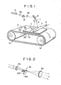
- an endless belt 2 provided with a magnet layer 2a overlaid on the surface is driveably positioned around a pair of rollers la and lb.
- a stimulable phosphor sheet 3 is closely contacted with the magnet layer 2a of the endless belt 2 by magnetic attraction.
- the rollers la and lb are rotated to move the endless belt 2 in the direction as indicated by the arrow A.
- a laser beam 4 emitted from a laser beam source 5 is made to impinge upon the stimulable phosphor sheet 3 via a galvanometer mirror 6 so as to scan the sheet 3 in the direction as indicated by the arrow B normal to the moving direction A of the endless belt 2.
- the stimulable phosphor sheet 3 is two-dimensionally scanned by the laser beam 4. That is, the stimulable phosphor sheet 3 is scanned in the sub-scanning direction as indicated by the arrow A by the sub-scanning means comprising a pair of rollers la and lb and the endless belt 2, and in the main scanning direction as indicated by the arrow B normal to the sub-scanning direction by the galvanometer mirror 6 acting as the main scanning means.
- the endless belt 2 comprises a flexible endless belt substrate 2b and the magnet layer 2a overlaid on the substrate 2b.
- a beam expander comprising convex lenses 9a and 9b and acting as a beam converging means is positioned in the optical path between the laser beam source 5 and the galvanometer mirror 6.
- a rotatable light shielding means 10 for intercepting the laser beam 4 during the backward scanning period in synchronization with the forward and backward scanning in the main scanning direction conducted by the galvanometer mirror 6.
- the purpose ot expanding the laser beam 4 by the beam expander lenses 9a and 9b is to minimize the size of the light spot ultimately formed on the stimulable phosphor sheet 3.
- the laser beam 4 expanded by the beam expander lenses 9a and 9b is converged by an image forming lens 11 onto the stimulable phosphor sheet 3.
- the stimulable phosphor sheet 3 comprises a magnetic material layer 3a and a stimulable phosphor layer 3b laid on the magnetic material layer 3a.
- the stimulable phosphor layer 3b carries a radiation transmission image of an object stored therein.
- the portion of the sheet 3 exposed to the laser beam 4 emits light in proportion to the radiation energy stored.
- the emitted light enters a light guide member 7 fabricated, for example, by forming an acrylic plate, and is guided inside of the light guide member 7 by total reflection to a photodetector 8 such as a photomultiplier, which detects and converts the light into electric image signals.
- a photodetector 8 such as a photomultiplier
- FIG 2 is an enlarged schematic view showing the rotatable light shielding means 10 and the beam expander lenses 9a and 9b of Figure 1.
- the laser beam impinging upon the first lens 9a of the beam expander is converged thereby and then diverges.
- the beam diameter of the laser beam is then expanded by the second lens 9b.
- a sector 10a provided with a rotation shaft approximately parallel to the laser beam and rotated by a rotating motor 10b in synchronization with the forward and backward scanning in the main scanning direction conducted by the galvanometer mirror 6.
- the sector 10a is constituted by a fan-like light shielding member, and the rotation timing and the angle at the circumference of the sector 10a are adjusted to intercept the laser beam only during the backward scanning period in accordance with a synchronizing signal sent from the galvanometer mirror 6.
- the sector 10a since the sector 10a is installed at the beam converging position, it is possible to minimize the size of the sector 10a. Further, since interception of the laser beam can be achieved simply by rotating the sector 10a in a single direction by the rotating motor lOb, the interception of the laser beam can be conducted easily in conformity with the high speed scanning by the galvanometer mirror 6.
- Figure 2A shows a disk 10h which is advantageous in that it does not generate wind during rotation.
- the disk 10h is fabricated of a transparent glass plate or a transparent acrylic plate and provided with two light shielding portions on which a light shielding member is applied to intercept the laser beam during the backward scanning period.
- the light shielding portions and portions permeable to light are alternately positioned at approximately 90° intervals on the disk 10h, and the rotation of the disk 10h is timed so that the light shielding portions intercept the passage of the laser beam only during the backward scanning period on the basis of the synchronizing signal sent from the galvanometer mirror 6.
- the angle ratio of the light shielding portions to the portions permeable to light or the numbers of the respective portions may be changed when necessary.
- Figure 3A is a perspective view showing another embodiment of the light shielding means of the apparatus for reading out an image by scanning in accordance with the present invention
- Figure 3B is a schematic view showing the light shielding means of Figure 3A positioned in the optical path of the laser beam.
- a light shielding member 10c is secured to a rotation shaft 10d of a galvanometer 10e.
- the rotation shaft 10d is positioned approximately normal to the laser beam, and the light shielding member 10c is rotated forwardly and backwardly by the galvanometer 10e.
- the light shielding member 10c consists of a cylindrical light shielding material having a through groove laterally extending in the upper surface, and is installed at the beam converging position between the beam expander lenses 9a and 9b.
- the galvanometer 10e is rotated forwardly and backwardly in synchronization with the forward and backward scanning in the main scanning direction conducted by the galvanometer mirror 6. That is, the galvanometer 10e rotates the light shielding member 10c forwardly and backwardly so that the laser beam passes through the groove of the light shielding member 10c during the forward scanning period and is intercepted by the wall portions on both sides of the groove during the backward scanning period.
- the light shielding member 10c is installed at the beam converging position, it is possible to minimize the size of the light shielding member lOc.
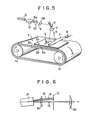
- FIG. 4 is a schematic view showing a further embodiment of the light shielding means of the apparatus for reading out an image by scanning in accordance with the present invention.
- a piston type light shielding member 10f consisting of a metal plate is installed approximately normal to the laser beam at the beam converging position between the beam expander lenses 9a and 9b.
- a solenoid lOg is positioned below the light shielding member 10f to vertically move the light shielding member 10f in synchronization with the forward and backward scanning in the main scanning direction conducted by the galvanometer mirror 6. Namely, the light shielding member 10f is moved vertically so that it is positioned below the laser beam to pass the laser beam during the forward scanning period and raised to intercept the laser beam during the backward scanning period.
- the acousto-optic modulator 12 is controlled in synchronization with the forward and backward scanning in the main scanning direction conducted by the galvanometer mirror 6 so as to modulate the laser beam 4 emitted by the laser beam source 5 only during the backward scanning period and not to modulate the laser beam during the forward scanning period.
- the zero-order diffracted light component passing through the acousto-optic modulator 12 is converged by the first convex lens 9a of the beam converging means 9 and passed through the pinhole of the light shielding plate 10' installed at the converging position.
- the zero-order diffracted light component is then converted by the second convex lens 9b into parallel rays of light and made to impinge upon the galvanometer mirror 6.
- the acousto-optic modulator 12 diffracts the laser beam at the maximum modulation efficiency and converts most (90% to 95%) of the light amount of the laser beam impinging upon the modulator 12 into the diffracted light components other than the zero-order diffracted light component. At this time, a portion within the range of approximately 5% to 10% of the light amount of the laser beam impinging upon the modulator 12 remains as the zero-order diffracted light component.
- the diffracted light components other than the zero-order diffracted light component are intercepted by the light shielding plate 10', and the zero-order diffracted light component is passed through the pinhole of the light shielding plate 10'.
Landscapes
- Engineering & Computer Science (AREA)
- Multimedia (AREA)
- Signal Processing (AREA)
- Physics & Mathematics (AREA)
- Optics & Photonics (AREA)
- General Physics & Mathematics (AREA)
- Facsimile Scanning Arrangements (AREA)
- Radiography Using Non-Light Waves (AREA)
Applications Claiming Priority (4)
| Application Number | Priority Date | Filing Date | Title |
|---|---|---|---|
| JP113675/83 | 1983-06-24 | ||
| JP58113675A JPS605665A (ja) | 1983-06-24 | 1983-06-24 | 画像走査読取装置 |
| JP58115471A JPS607416A (ja) | 1983-06-27 | 1983-06-27 | 画像走査読取装置 |
| JP115471/83 | 1983-06-27 |
Publications (3)
| Publication Number | Publication Date |
|---|---|
| EP0129831A2 true EP0129831A2 (fr) | 1985-01-02 |
| EP0129831A3 EP0129831A3 (en) | 1987-01-07 |
| EP0129831B1 EP0129831B1 (fr) | 1989-08-16 |
Family
ID=26452616
Family Applications (1)
| Application Number | Title | Priority Date | Filing Date |
|---|---|---|---|
| EP84107025A Expired EP0129831B1 (fr) | 1983-06-24 | 1984-06-19 | Appareil d'analyse et de lecture d'images |
Country Status (3)
| Country | Link |
|---|---|
| US (1) | US4582989A (fr) |
| EP (1) | EP0129831B1 (fr) |
| DE (1) | DE3479469D1 (fr) |
Cited By (1)
| Publication number | Priority date | Publication date | Assignee | Title |
|---|---|---|---|---|
| EP0275116A3 (en) * | 1987-01-16 | 1989-08-09 | Fuji Photo Film Co., Ltd. | Radiation image read-out apparatus radiation image read-out apparatus |
Families Citing this family (12)
| Publication number | Priority date | Publication date | Assignee | Title |
|---|---|---|---|---|
| JPS6087565A (ja) * | 1983-10-19 | 1985-05-17 | Fuji Photo Film Co Ltd | 画像走査読取方法 |
| US4785183A (en) * | 1985-09-18 | 1988-11-15 | Konishiroku Photo Industry Co., Ltd. | Method for reading radiation image information |
| US4893012A (en) * | 1987-01-13 | 1990-01-09 | Fuji Photo Film Co., Ltd. | Radiation image read-out and reproducing apparatus |
| DE3810094A1 (de) * | 1988-03-25 | 1989-10-05 | Agfa Gevaert Ag | Roentgenaufnahmefolie mit einer stimulierbaren phosphorschicht und geraet zu deren behandlung und auswertung |
| US5635728A (en) * | 1995-06-19 | 1997-06-03 | Denoptix, Inc. | Rotating scanner system for reading multiple storage layer radiation screens |
| JP3458035B2 (ja) * | 1996-02-05 | 2003-10-20 | 富士写真フイルム株式会社 | 走査装置 |
| US6624438B2 (en) | 1997-11-20 | 2003-09-23 | Orex Computed Radiography Ltd. | Scanning apparatus |
| US6198111B1 (en) * | 1998-10-14 | 2001-03-06 | Alara, Inc. | Scanning system with flexible drive assembly |
| KR20010110408A (ko) | 1998-11-25 | 2001-12-13 | 추후제출 | 단일 헤드를 갖는 형광 스크린 스캐닝 장치 |
| US20030042445A1 (en) * | 2001-08-30 | 2003-03-06 | Mitchell Christopher R. | Apparatus for reading storage layer radiation screens |
| US20050012057A1 (en) * | 2003-05-08 | 2005-01-20 | Alara, Inc. | Method and apparatus for radiation image erasure |
| EP2568332B1 (fr) * | 2011-09-06 | 2014-03-12 | Agfa HealthCare N.V. | Dispositif et système destinés à la lecture d'informations radiographiques stockées dans des plaques fluorescentes de mémoire |
Family Cites Families (6)
| Publication number | Priority date | Publication date | Assignee | Title |
|---|---|---|---|---|
| US1752876A (en) * | 1926-08-09 | 1930-04-01 | Gen Electric | Transmission of pictures |
| CA1002653A (en) * | 1972-02-22 | 1976-12-28 | Xerox Corporation | Laser scanner |
| JPS5597963A (en) * | 1979-01-20 | 1980-07-25 | Canon Inc | Image forming device |
| JPS55111917A (en) * | 1979-02-22 | 1980-08-29 | Toshiba Corp | Reciprocating photo scanner |
| JPS561923A (en) * | 1979-06-20 | 1981-01-10 | Dainippon Screen Mfg Co Ltd | Stabilizing method for quantity of light in optical system using light deflecting element |
| JPS6028468B2 (ja) * | 1980-10-30 | 1985-07-04 | 富士写真フイルム株式会社 | 放射線画像情報読取方法および装置 |
-
1984
- 1984-06-19 DE DE8484107025T patent/DE3479469D1/de not_active Expired
- 1984-06-19 EP EP84107025A patent/EP0129831B1/fr not_active Expired
- 1984-06-20 US US06/622,378 patent/US4582989A/en not_active Expired - Lifetime
Cited By (1)
| Publication number | Priority date | Publication date | Assignee | Title |
|---|---|---|---|---|
| EP0275116A3 (en) * | 1987-01-16 | 1989-08-09 | Fuji Photo Film Co., Ltd. | Radiation image read-out apparatus radiation image read-out apparatus |
Also Published As
| Publication number | Publication date |
|---|---|
| DE3479469D1 (en) | 1989-09-21 |
| EP0129831A3 (en) | 1987-01-07 |
| EP0129831B1 (fr) | 1989-08-16 |
| US4582989A (en) | 1986-04-15 |
Similar Documents
| Publication | Publication Date | Title |
|---|---|---|
| US4582989A (en) | Image scanning read-out apparatus | |
| US4689482A (en) | Multiple laser beam scanner with beam intensity control | |
| US4889990A (en) | Method and apparatus for recording and reproducing electron microscope image | |
| EP0392504B1 (fr) | Procédé de génération de signaux d'images à radiation | |
| CA1219075A (fr) | Appareil d'extraction d'images | |
| US4930869A (en) | Light beam scanning device | |
| EP0144963B1 (fr) | Appareil de lecture d'images de radiation | |
| JPS6239842A (ja) | 放射線画像情報読取方法 | |
| US4958893A (en) | Semiconductor laser beam source apparatus | |
| JP3313237B2 (ja) | 画像読取装置および画像記録装置 | |
| US4800276A (en) | Radiation image read-out apparatus | |
| US5086228A (en) | Method for eliminating nonuniformity in sensitivity in image read-out apparatuses | |
| CA1223982A (fr) | Appareil d'affichage d'images | |
| US4661708A (en) | Radiation image read-out apparatus | |
| US4816688A (en) | Radiation image read-out apparatus for stimulable phosphor sheet | |
| US4908511A (en) | Light beam scanning device | |
| US5059795A (en) | Multiple beam radiation image reading apparatus | |
| JPS607416A (ja) | 画像走査読取装置 | |
| US5461238A (en) | Radiation image read-out apparatus | |
| US4873440A (en) | Electron microscope image output method and apparatus | |
| JPH03198039A (ja) | 画像読取装置 | |
| JPS60120346A (ja) | 放射線画像情報記録読取方法および装置 | |
| JPS6157921A (ja) | 光ビ−ム走査装置 | |
| JP2575418B2 (ja) | 光ビーム走査装置 | |
| JPH01237637A (ja) | 放射線画像情報読取装置 |
Legal Events
| Date | Code | Title | Description |
|---|---|---|---|
| PUAI | Public reference made under article 153(3) epc to a published international application that has entered the european phase |
Free format text: ORIGINAL CODE: 0009012 |
|
| AK | Designated contracting states |
Designated state(s): DE FR NL |
|
| PUAL | Search report despatched |
Free format text: ORIGINAL CODE: 0009013 |
|
| AK | Designated contracting states |
Kind code of ref document: A3 Designated state(s): DE FR NL |
|
| 17P | Request for examination filed |
Effective date: 19870225 |
|
| 17Q | First examination report despatched |
Effective date: 19890124 |
|
| GRAA | (expected) grant |
Free format text: ORIGINAL CODE: 0009210 |
|
| AK | Designated contracting states |
Kind code of ref document: B1 Designated state(s): DE FR NL |
|
| REF | Corresponds to: |
Ref document number: 3479469 Country of ref document: DE Date of ref document: 19890921 |
|
| ET | Fr: translation filed | ||
| PLBE | No opposition filed within time limit |
Free format text: ORIGINAL CODE: 0009261 |
|
| STAA | Information on the status of an ep patent application or granted ep patent |
Free format text: STATUS: NO OPPOSITION FILED WITHIN TIME LIMIT |
|
| 26N | No opposition filed | ||
| PGFP | Annual fee paid to national office [announced via postgrant information from national office to epo] |
Ref country code: DE Payment date: 20020429 Year of fee payment: 19 |
|
| PGFP | Annual fee paid to national office [announced via postgrant information from national office to epo] |
Ref country code: NL Payment date: 20020617 Year of fee payment: 19 Ref country code: FR Payment date: 20020617 Year of fee payment: 19 |
|
| PG25 | Lapsed in a contracting state [announced via postgrant information from national office to epo] |
Ref country code: NL Free format text: LAPSE BECAUSE OF NON-PAYMENT OF DUE FEES Effective date: 20040101 Ref country code: DE Free format text: LAPSE BECAUSE OF NON-PAYMENT OF DUE FEES Effective date: 20040101 |
|
| PG25 | Lapsed in a contracting state [announced via postgrant information from national office to epo] |
Ref country code: FR Free format text: LAPSE BECAUSE OF NON-PAYMENT OF DUE FEES Effective date: 20040227 |
|
| NLV4 | Nl: lapsed or anulled due to non-payment of the annual fee |
Effective date: 20040101 |
|
| REG | Reference to a national code |
Ref country code: FR Ref legal event code: ST |