EP0129855A2 - Système de transmission, en particulier pour équipements numériques de transmission de faisceaux hertziens - Google Patents
Système de transmission, en particulier pour équipements numériques de transmission de faisceaux hertziens Download PDFInfo
- Publication number
- EP0129855A2 EP0129855A2 EP84107124A EP84107124A EP0129855A2 EP 0129855 A2 EP0129855 A2 EP 0129855A2 EP 84107124 A EP84107124 A EP 84107124A EP 84107124 A EP84107124 A EP 84107124A EP 0129855 A2 EP0129855 A2 EP 0129855A2
- Authority
- EP
- European Patent Office
- Prior art keywords
- digital
- intermediate point
- bit
- auxiliary signals
- auxiliary
- Prior art date
- Legal status (The legal status is an assumption and is not a legal conclusion. Google has not performed a legal analysis and makes no representation as to the accuracy of the status listed.)
- Ceased
Links
Images
Classifications
-
- H—ELECTRICITY
- H04—ELECTRIC COMMUNICATION TECHNIQUE
- H04J—MULTIPLEX COMMUNICATION
- H04J3/00—Time-division multiplex systems
- H04J3/02—Details
- H04J3/12—Arrangements providing for calling or supervisory signals
Definitions
- the invention relates to a method and an arrangement for the transmission of digital auxiliary signals in digital radio relay systems with two end points and at least one intermediate point arranged between them with a receiving and a transmitting part by means of additional bits, the arrangement of which is determined by an upper frame.
- auxiliary signals for system-internal purposes in addition to the actual baseband signal.
- Such auxiliary signals are required for the service call, for equivalent switching commands and for remote monitoring.
- analog service channels with the properties of analog telephone channels are usually provided.
- the analog signals in these channels are transmitted in the baseband below the frequency range of the useful signal.
- analog service channels are implemented in such a way that the digitally modulated carrier is additionally frequency-modulated with the analog auxiliary signals.
- auxiliary signals can be easily transmitted in digital form. For this purpose, additional bits are inserted in the digital signal to be transmitted in the sending terminal. The digital signal with the additional bits is transmitted via intermediate points to the receiving end station, where the original digital signal again after removing the additional bits will be produced. The arrangement of the additional bits is determined by the upper frame. Additional bits are frame identification bits, parity bits and service bits. Service bits are used for the RF channel identification and for the transmission of the digital auxiliary signals. This requires a procedure for feeding and branching the digital auxiliary signals at end and intermediate points.
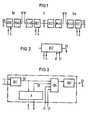
- the terminal transmitter Se consists of a baseband processor BSE, a modulator M and a transmitter part S.
- the terminal receiver Em consists of a receiver unit E, a demodulator D and a baseband processor BEE.
- an intermediate point receiver E and an intermediate point transmitter S are connected at their baseband connections.
- the intermediate station receiver differs from the end station receiver in the baseband processing BEZ.
- the intermediate station transmitter differs from the end station transmitter in the baseband processing BSZ.
- the additional bits are inserted into the digital signal D2 supplied at the connection A.
- the digital signal with an increased bit rate is transmitted via the intermediate point Z to the Eadstelien receiver Em, where the baseband processor BEE evaluates the additional bits, removes them from the digital signal D1 and outputs the original digital signal D2 at the connection C.
- the digital signal D2 in the baseband preparations only undergoes differential decoding in the receiving baseband processing BEZ and differential coding in the transmitting baseband processing BSZ.
- the additional bits are also evaluated in a secondary path.
- the transmission of the digital auxiliary signals is shown in FIG. 1 using the example of a single signal.
- the baseband processing BSE in the terminal transmitter.Se has an output for the clock ' T and an input for the digital auxiliary signal H.
- the clock T is tied to the clock of the digital signal D2.
- the interface for the digital auxiliary signal is therefore counter-directional, ie the digital auxiliary signal H is queried from its source with the clock T (cf. the magazine telcom report 4 (1980), pages 344 to 352).
- the bits of the auxiliary signal are inserted as additional bits at the designated place on the upper frame.
- the invention has for its object to provide a method and an arrangement for its implementation, which enable the transmission of digital auxiliary signals without restriction between the end or intermediate point of a radio link with little effort.
- the additional bits are evaluated in the baseband preparation of the intermediate point receiver because of the quality monitoring of the route and the RF channel identification. This requires recognition of the superframe with the generation of frames and bit clocks. It is therefore possible with minimal additional effort to overwrite digital auxiliary signals supplied in the baseband processing into the positions of the corresponding additional bits.
- each digital auxiliary signal supplied at an intermediate point is assigned a binary control signal, the binary value of which indicates whether the auxiliary signal is overwritten in the assigned bit position or not.
- An arrangement for carrying out the method according to the invention is advantageously designed such that in the baseband processing of the receiving part of the intermediate point (s) there is a differential decoder and parallel series converter and an evaluation circuit connected to it with connections for the clock and the given auxiliary signal from the transmitting one Terminal are switched on and a gate circuit also connected to the output of the differential decoder and parallel series converter, to which the additional digital auxiliary signals to be transmitted and the associated control signals from the outside as well as the associated bit clocks are fed from the evaluation circuit.
- the output of the gate circuit is advantageously connected to the transmitting part of the intermediate point (s) via an interface circuit.
- Control signal its characteristic state, e.g. assumes the logical value 1, the associated bit clock TB switches the associated auxiliary signal into the signal path for one bit period of the digital signal D2.
Landscapes
- Engineering & Computer Science (AREA)
- Computer Networks & Wireless Communication (AREA)
- Signal Processing (AREA)
- Time-Division Multiplex Systems (AREA)
- Mobile Radio Communication Systems (AREA)
- Radio Relay Systems (AREA)
Applications Claiming Priority (2)
| Application Number | Priority Date | Filing Date | Title |
|---|---|---|---|
| DE19833322851 DE3322851A1 (de) | 1983-06-24 | 1983-06-24 | Verfahren und anordnung zur uebertragung von digitalen hilfssignalen in digital-richtfunksystemen |
| DE3322851 | 1983-06-24 |
Publications (2)
| Publication Number | Publication Date |
|---|---|
| EP0129855A2 true EP0129855A2 (fr) | 1985-01-02 |
| EP0129855A3 EP0129855A3 (fr) | 1987-10-21 |
Family
ID=6202340
Family Applications (1)
| Application Number | Title | Priority Date | Filing Date |
|---|---|---|---|
| EP84107124A Ceased EP0129855A3 (fr) | 1983-06-24 | 1984-06-20 | Système de transmission, en particulier pour équipements numériques de transmission de faisceaux hertziens |
Country Status (3)
| Country | Link |
|---|---|
| EP (1) | EP0129855A3 (fr) |
| AU (1) | AU579825B2 (fr) |
| DE (1) | DE3322851A1 (fr) |
Cited By (1)
| Publication number | Priority date | Publication date | Assignee | Title |
|---|---|---|---|---|
| AU579825B2 (en) * | 1983-06-24 | 1988-12-15 | Siemens Aktiengesellschaft | Method and apparatus for the transmission of digital auxiliary signals in digital radio relay systems |
Families Citing this family (2)
| Publication number | Priority date | Publication date | Assignee | Title |
|---|---|---|---|---|
| DE3327517A1 (de) * | 1983-07-29 | 1985-02-07 | Siemens AG, 1000 Berlin und 8000 München | Verfahren und anordnung zur ueberwachung von digital-richtfunkstrecken |
| NO169748C (no) * | 1986-03-10 | 1992-07-29 | Siemens Ag | Innretning til aa foeye inn lokale analoge tjenestesignaleri digital-tjenestekanaler i en retningsradio-forbindelse |
Family Cites Families (4)
| Publication number | Priority date | Publication date | Assignee | Title |
|---|---|---|---|---|
| GB1401261A (en) * | 1972-01-13 | 1975-07-16 | Siemens Ag | Data transmission systems |
| NO154368C (no) * | 1980-07-22 | 1986-09-03 | Siemens Ag | Fremgangsmaate til overvaakning av mellomregeneratorer samt mellomregeneratorer til gjennomfoerelse av fremgangsmaaten. |
| DE3322851A1 (de) * | 1983-06-24 | 1985-01-03 | Siemens AG, 1000 Berlin und 8000 München | Verfahren und anordnung zur uebertragung von digitalen hilfssignalen in digital-richtfunksystemen |
| DE3327517A1 (de) * | 1983-07-29 | 1985-02-07 | Siemens AG, 1000 Berlin und 8000 München | Verfahren und anordnung zur ueberwachung von digital-richtfunkstrecken |
-
1983
- 1983-06-24 DE DE19833322851 patent/DE3322851A1/de not_active Withdrawn
-
1984
- 1984-06-20 EP EP84107124A patent/EP0129855A3/fr not_active Ceased
- 1984-06-22 AU AU29765/84A patent/AU579825B2/en not_active Ceased
Cited By (1)
| Publication number | Priority date | Publication date | Assignee | Title |
|---|---|---|---|---|
| AU579825B2 (en) * | 1983-06-24 | 1988-12-15 | Siemens Aktiengesellschaft | Method and apparatus for the transmission of digital auxiliary signals in digital radio relay systems |
Also Published As
| Publication number | Publication date |
|---|---|
| EP0129855A3 (fr) | 1987-10-21 |
| AU2976584A (en) | 1985-01-03 |
| AU579825B2 (en) | 1988-12-15 |
| DE3322851A1 (de) | 1985-01-03 |
Similar Documents
| Publication | Publication Date | Title |
|---|---|---|
| DE2528835C2 (de) | Einrichtung zur Übertragung von digitalen Signalen, insbesondere Mikrowellensignalen, zwischen einer Sendestation und einer Empfangsstation | |
| DE69530665T2 (de) | Verfahren und gerät zur sprachübertragung in einem mobilen kommunikationssystem | |
| DE2319569B2 (de) | Kabelf ernse hsystem | |
| DE3739484C2 (fr) | ||
| DE3125724C2 (fr) | ||
| EP0129855A2 (fr) | Système de transmission, en particulier pour équipements numériques de transmission de faisceaux hertziens | |
| EP0048859A1 (fr) | Procédé pour la reconnaissance d'informations numériques lors d'une transmission numérique d'information, en particulier une transmission d'information dans des systèmes de communication entre postes radioélectriques mobiles | |
| DE3308703C2 (fr) | ||
| EP0744114B1 (fr) | Procede de transmission de signaux vocaux codes dans au moins un reseau de telecommunications | |
| DE3120761C2 (de) | Schaltung zum schnellen Erkennen von FSK-Signalen in einem Funkkanal | |
| DE2828602B1 (de) | Verfahren zum UEbertragen von Daten in einem synchronen Datennetz | |
| DE1912791A1 (de) | Langstrecken-Richtfunkanlage | |
| DE4236002A1 (de) | Verfahren und Schaltungsanordnung zur Verbindung mehrerer digitaler Datenkanäle zu einem Übertragungskanal | |
| DE4328487C2 (de) | Verfahren und Schaltungsanordnung zum Übertragen von Datenströmen über Zweidraht-Basisteilnehmeranschlußleitungen | |
| DE3033871A1 (de) | Nachrichtenuebertragungssystem | |
| DE2362855A1 (de) | Verfahren zur uebertragung von digitalen signalen | |
| EP0564697B1 (fr) | Réseau radio mobile avec transmission au choix de parole ou de données protégées contre les erreurs | |
| EP0063638A2 (fr) | Système de télécommunication numérique | |
| EP0038509A1 (fr) | Circuit logique pour éviter un état de verrouillage entre des bus de données distants l'un de l'autre | |
| DE2705786B2 (de) | Einrichtung zur Durchführung von Kontrollmessungen in einem NachrichtenÜbertragungssystem | |
| DE3607762C2 (de) | Automatische Fernsteuerungsvorrichtung | |
| EP0133278A2 (fr) | Procédé et dispositif pour la surveillance de liaisons hertziennes numériques | |
| EP0238910B1 (fr) | Dispositif pour insérer des signaux de service locaux analogiques dans des canaux de service numériques d'une liaison à faisceaux hertziens | |
| EP0046846B1 (fr) | Système de communication par câble | |
| DE3412508A1 (de) | Einrichtung zur uebertragung von elektrischen signalen, insbesondere im langwellenbereich |
Legal Events
| Date | Code | Title | Description |
|---|---|---|---|
| PUAI | Public reference made under article 153(3) epc to a published international application that has entered the european phase |
Free format text: ORIGINAL CODE: 0009012 |
|
| AK | Designated contracting states |
Designated state(s): AT BE CH DE FR GB IT LI NL SE |
|
| PUAL | Search report despatched |
Free format text: ORIGINAL CODE: 0009013 |
|
| AK | Designated contracting states |
Kind code of ref document: A3 Designated state(s): AT BE CH DE FR GB IT LI NL SE |
|
| 17P | Request for examination filed |
Effective date: 19880309 |
|
| 17Q | First examination report despatched |
Effective date: 19891023 |
|
| STAA | Information on the status of an ep patent application or granted ep patent |
Free format text: STATUS: THE APPLICATION HAS BEEN REFUSED |
|
| 18R | Application refused |
Effective date: 19910812 |
|
| RIN1 | Information on inventor provided before grant (corrected) |
Inventor name: KUEHNE, FRIEDRICH, DR. Inventor name: KAHN, KLAUS-DIETER, DIPL.-ING. |