EP0129868A1 - Auswechselbare Lampeneinheit die die Dichtung und die Justierung der Lampe gewährleistet und Kraftfahrzeugscheinwerfer mit solcher Lampeneinheit - Google Patents
Auswechselbare Lampeneinheit die die Dichtung und die Justierung der Lampe gewährleistet und Kraftfahrzeugscheinwerfer mit solcher Lampeneinheit Download PDFInfo
- Publication number
- EP0129868A1 EP0129868A1 EP84107173A EP84107173A EP0129868A1 EP 0129868 A1 EP0129868 A1 EP 0129868A1 EP 84107173 A EP84107173 A EP 84107173A EP 84107173 A EP84107173 A EP 84107173A EP 0129868 A1 EP0129868 A1 EP 0129868A1
- Authority
- EP
- European Patent Office
- Prior art keywords
- holder
- lamp unit
- lamp
- reflector
- electrically
- Prior art date
- Legal status (The legal status is an assumption and is not a legal conclusion. Google has not performed a legal analysis and makes no representation as to the accuracy of the status listed.)
- Granted
Links
- 239000011521 glass Substances 0.000 claims abstract description 8
- 239000004033 plastic Substances 0.000 claims abstract description 7
- 229920003023 plastic Polymers 0.000 claims abstract description 7
- 239000012812 sealant material Substances 0.000 claims abstract description 6
- 229910052721 tungsten Inorganic materials 0.000 claims description 13
- 239000010937 tungsten Substances 0.000 claims description 13
- 229910052736 halogen Inorganic materials 0.000 claims description 12
- -1 tungsten halogen Chemical class 0.000 claims description 9
- 239000004568 cement Substances 0.000 claims description 8
- 239000000565 sealant Substances 0.000 claims description 7
- 229910000679 solder Inorganic materials 0.000 claims description 7
- 238000002788 crimping Methods 0.000 claims description 5
- 239000000463 material Substances 0.000 claims description 5
- 239000004593 Epoxy Substances 0.000 claims description 2
- 238000007373 indentation Methods 0.000 claims description 2
- 238000005476 soldering Methods 0.000 abstract description 4
- 230000000694 effects Effects 0.000 description 5
- 239000000203 mixture Substances 0.000 description 4
- 230000003287 optical effect Effects 0.000 description 4
- WFKWXMTUELFFGS-UHFFFAOYSA-N tungsten Chemical compound [W] WFKWXMTUELFFGS-UHFFFAOYSA-N 0.000 description 4
- 230000002411 adverse Effects 0.000 description 3
- 230000009977 dual effect Effects 0.000 description 3
- 150000004820 halides Chemical class 0.000 description 3
- 150000002367 halogens Chemical class 0.000 description 3
- LQBJWKCYZGMFEV-UHFFFAOYSA-N lead tin Chemical compound [Sn].[Pb] LQBJWKCYZGMFEV-UHFFFAOYSA-N 0.000 description 3
- 229910052751 metal Inorganic materials 0.000 description 3
- 239000002184 metal Substances 0.000 description 3
- 238000000151 deposition Methods 0.000 description 2
- 150000002739 metals Chemical class 0.000 description 2
- 239000004417 polycarbonate Substances 0.000 description 2
- 229920000515 polycarbonate Polymers 0.000 description 2
- 230000000717 retained effect Effects 0.000 description 2
- 239000010959 steel Substances 0.000 description 2
- 229910000838 Al alloy Inorganic materials 0.000 description 1
- 229910000851 Alloy steel Inorganic materials 0.000 description 1
- 229910001369 Brass Inorganic materials 0.000 description 1
- RYGMFSIKBFXOCR-UHFFFAOYSA-N Copper Chemical compound [Cu] RYGMFSIKBFXOCR-UHFFFAOYSA-N 0.000 description 1
- 229910000881 Cu alloy Inorganic materials 0.000 description 1
- 229910001030 Iron–nickel alloy Inorganic materials 0.000 description 1
- 239000004952 Polyamide Substances 0.000 description 1
- 239000004734 Polyphenylene sulfide Substances 0.000 description 1
- 239000004793 Polystyrene Substances 0.000 description 1
- 229910000831 Steel Inorganic materials 0.000 description 1
- 230000004308 accommodation Effects 0.000 description 1
- 150000001252 acrylic acid derivatives Chemical class 0.000 description 1
- 229920006397 acrylic thermoplastic Polymers 0.000 description 1
- XAGFODPZIPBFFR-UHFFFAOYSA-N aluminium Chemical compound [Al] XAGFODPZIPBFFR-UHFFFAOYSA-N 0.000 description 1
- 238000005452 bending Methods 0.000 description 1
- 239000010951 brass Substances 0.000 description 1
- 239000011248 coating agent Substances 0.000 description 1
- 238000000576 coating method Methods 0.000 description 1
- 230000006835 compression Effects 0.000 description 1
- 238000007906 compression Methods 0.000 description 1
- 239000010949 copper Substances 0.000 description 1
- 230000008021 deposition Effects 0.000 description 1
- 239000000428 dust Substances 0.000 description 1
- 229920001971 elastomer Polymers 0.000 description 1
- 239000012943 hotmelt Substances 0.000 description 1
- 230000037431 insertion Effects 0.000 description 1
- 238000003780 insertion Methods 0.000 description 1
- 239000007788 liquid Substances 0.000 description 1
- 230000014759 maintenance of location Effects 0.000 description 1
- 238000004519 manufacturing process Methods 0.000 description 1
- 238000000465 moulding Methods 0.000 description 1
- 229920003229 poly(methyl methacrylate) Polymers 0.000 description 1
- 229920002647 polyamide Polymers 0.000 description 1
- 229920000728 polyester Polymers 0.000 description 1
- 235000013824 polyphenols Nutrition 0.000 description 1
- 229920000069 polyphenylene sulfide Polymers 0.000 description 1
- 229920001296 polysiloxane Polymers 0.000 description 1
- 229920002223 polystyrene Polymers 0.000 description 1
- 239000000843 powder Substances 0.000 description 1
- 239000005060 rubber Substances 0.000 description 1
- 229920002379 silicone rubber Polymers 0.000 description 1
- 238000009987 spinning Methods 0.000 description 1
- 239000010935 stainless steel Substances 0.000 description 1
- 229910001220 stainless steel Inorganic materials 0.000 description 1
- 229920003051 synthetic elastomer Polymers 0.000 description 1
- 239000005061 synthetic rubber Substances 0.000 description 1
- ISXSCDLOGDJUNJ-UHFFFAOYSA-N tert-butyl prop-2-enoate Chemical compound CC(C)(C)OC(=O)C=C ISXSCDLOGDJUNJ-UHFFFAOYSA-N 0.000 description 1
- 150000003673 urethanes Chemical class 0.000 description 1
- 238000003466 welding Methods 0.000 description 1
Images
Classifications
-
- H—ELECTRICITY
- H01—ELECTRIC ELEMENTS
- H01K—ELECTRIC INCANDESCENT LAMPS
- H01K1/00—Details
- H01K1/42—Means forming part of the lamp for the purpose of providing electrical connection, or support for, the lamp
- H01K1/46—Means forming part of the lamp for the purpose of providing electrical connection, or support for, the lamp supported by a separate part, e.g. base, cap
-
- F—MECHANICAL ENGINEERING; LIGHTING; HEATING; WEAPONS; BLASTING
- F21—LIGHTING
- F21S—NON-PORTABLE LIGHTING DEVICES; SYSTEMS THEREOF; VEHICLE LIGHTING DEVICES SPECIALLY ADAPTED FOR VEHICLE EXTERIORS
- F21S41/00—Illuminating devices specially adapted for vehicle exteriors, e.g. headlamps
- F21S41/10—Illuminating devices specially adapted for vehicle exteriors, e.g. headlamps characterised by the light source
- F21S41/19—Attachment of light sources or lamp holders
- F21S41/198—Snap-fit attachments
Definitions
- the invention relates to automobile headlights and more particularly to those wherein a replaceable lamp unit assembly is utilized.
- Automobile headlights wherein a replaceable lamp unit is employed are known in the art. Examples are illustrated in U.S. Patents 3,688,103 (Daumuller), 3,593,017 (Cibie) and 2,750,491 (Anderson).
- the instant invention is related to lamps of the variety described above and in particular defines a replaceable lamp unit which provides both a hermetic seal for the unit within the headlight's reflector and also assures that the electric lamp utilized therewith will be maintained in strict alignment as is necessary in automotive headlights.
- hermetic seal is meant a seal which prevents the passage of moisture, dust and other elements which can adversely affect the operation of the headlight.
- excessive moisture entering the headlight can adversely affect the reflective coating typically utilized on the concave reflector of the headlight, and thus significantly reduce light output.
- the replaceable lamp unit defined herein assures that alignment of the electric lamp employed therewith will be maintained. That is, alignment of the glass envelope of the lamp relative to the unit's holder is provided such that the filament structure therein (either a singular coiled filament or two, spaced coiled filaments) will be accurately aligned relative to the optical axis of the reflector when the lamp unit is oriented within the reflector's rear opening.
- a preferred light source which constitutes an important part of the replaceable lamp unit defined herein is an electric lamp of the tungsten halogen variety.
- an electric lamp of the tungsten halogen variety is shown in U.S. Patent 3,829,729 (Westlund, Jr. et al), said patent assigned the same assignee as the instant invention.
- the tungsten which constitutes the filament material is normally evaporated from the filament during lamp operation and combines with the halogen to form a gaseous halide, said halide preventing the tungsten from depositing on the internal wall of the lamp's glass envelope.
- the halide Upon returning to the filament structure, the halide decomposes, resulting in the deposition of tungsten back onto the filament structure and the release of additional halogen gas to assure continuation of the cycle.
- the halogen cycle is well known in the art, and lamps employing it have been used for some time.
- a typical tungsten halogen lamp provides about 65 watts when operated at high beam and about 35 watts at low beam. Understandably, it is critical that the filament structure of the lamp within an automobile headlight be aligned relative to the reflector to provide optimum output of the finished headlight. As will be described below, such alignment constitutes an important feature of the replaceable lamp unit defined herein.
- a replaceable lamp unit capable of being removably positioned within the rear opening of a reflector which constitutes part of an automobile headlight.
- the replaceable lamp unit is designed for being electrically connected to an external connector which forms part of the electrical circuitry of the automobile.
- the lamp unit comprises an electrically insulative holder defining two cavities therein and a wall member located therebetween, said wall member including at least two spaced apart apertures therein. Fixedly secured within each of the apertures is an electrically conductive member which in turn is adapted to being electrically connected to the described external connector when the connector is located substantially within one of the holder's cavities.
- the lamp unit further comprises an electric lamp which is securedly positioned within the holder and includes an envelope projecting from the holder for being oriented within the reflector when the holder is located within the reflector's rear opening.
- the lamp unit includes at least two electrically conductive lead-in wires projecting from the envelope and extending within the first cavity of the holder. Each lead-in wire is electrically connected to a respective one of the fixedly secured electrically conductive members within the walls of the holder, the electrical connection further providing a hermetic seal between the conductive members and lead-in wires while also serving to maintain the lamp in a substantially fixed position within the holder.
- an automobile headlight which comprises a concave reflector (glass or plastic) including a rear opening therein, a front lens for directing light emitted from the electric lamp of the headlight and reflected by the reflector, and a replaceable lamp unit adapted for being removably positioned within the concave reflector's rear opening.
- the lamp unit includes an insulative holder for being positioned within the rear opening and defining a pair of cavities therein and a wall member located therebetween, said wall member including two spaced apart apertures therein. Within each aperture is an electrically conductive member adapted for being electrically connected to an external connector when the connector is substantially positioned within one of the holder's cavities.
- the headlight further comprises an electric lamp securedly positioned within the holder and including an envelope and at least two electrically conductive lead-in wires projecting from the envelope.
- Each of the lead-in wires is electrically connected to a respective one of-the conductive members secured within the holder's apertures, the electrical connection providing a hermetic seal between the conductive members and respective lead-in wires and also serving to maintain the electric lamp in a substantially fixed position within the holder.
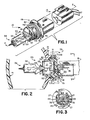
- FIG. 1 there is illustrated in a perspective view a replaceable lamp unit 10 capable of being removably positioned within the rear opening 11 (FIG. 2) of a reflector 13 (FIG. 2) which forms part of an automobile headlight.
- Lamp unit 10 is further designed for being electrically connected to an external connector 15 which comprises part of the electrical circuitry of the automobile employing the headlight.
- connector 15 is designed for being inserted within the rear portion of unit 10 after the unit has been positioned within the reflector's opening.
- Connector 15 includes a plurality of electrical wires 17 which also form part of the automobile's circuit. Wires 17 are thus either directly or indirectly connected to the power source (e.g., 12-volt battery) typically found in most automobiles.
- the power source e.g., 12-volt battery
- Unit 10 includes an electrically insulative holder 19 which defines therein a first cavity 21 and a second cavity 23, said cavities separated by a common wall member 25.
- Holder 19 is comprised of a heat and impact resistant plastic (e.g., preferably polyphenylene sulfide) and is thus readily suitable for use within the relatively harsh environment typically found about automobile headlights.
- a heat and impact resistant plastic e.g., preferably polyphenylene sulfide
- Unit 10 further includes at least two electrically conductive members 27 which are each fixedly secured within a respective one of a similar number of apertures 29 (one shown in FIG. 2) located within wall member 25. It is understood that a minimum of two apertures and corresponding electrically conductive members 27 are utilized in the instant invention. In one embodiment, three members 27 (and apertures 29) were utilized when holder 19 accommodated a dual filament tungsten halogen lamp.
- tungsten halogen lamps including a dual coil filament structure therein such as shown in FIG. 2) include at least four lead-in wires 31 (only one shown in FIG. 2) which project externally from the glass envelope 33 of the lamp. In the case of a single coil tungsten filament lamp, only two lead-in wires 31 are typically utilized. It is thus understood with regard to the invention, that holder 19 is adapted for accommodating both single and double coil filament tungsten halogen lamps.
- Each of the electrically conductive members 27 is preferably in the form of a conical shaped metal eyelet.
- a preferred material for each eyelet is tin-plated brass.
- Other suitable metals include aluminum, copper, steel, and nickel-iron alloy.
- each eyelet Electrically connected to each eyelet is a metallic lug member 35 which includes a base segment positioned firmly against wall 25 (FIG. 2) and an upstanding leg segment which extends within second cavity 23. Accordingly, each of the lug members 35 (a total of three are shown in the drawing) is designed for being inserted within a corresponding opening 37 of external connector 15 to provide electrical connection therewith when the connector is inserted within cavity 23.
- holder 19 is adapted for accommodating an electric lamp (39) which is preferably of the tungsten halogen variety.
- the envelope 33 of lamp 39 extends within the reflector and is substantially surrounded by the reflecting surfaces thereof in such a manner so as to provide optimum light output from the headlight (said headlight further including a forward lens member 41 designed for directing light in a predetermined pattern from the assembled unit). Understandably, alignment of envelope 33 relative to the reflective surfaces of reflector 13 such that the filament structure contained therein is precisely oriented relative to the reflector's optical axis is deemed critical to assure optimum light output.
- lamp.39 be initially oriented relative to holder 19 in a fixed relationship therewith such that when the holder is positioned within opening 11 of reflector 13, this critical alignment is attained.
- precisioned alignment constitutes an important feature of the instant invention, in addition to the provision of the aforementioned hermetic seal.
- each of the lead-in wires 31 is shown projecting from envelope 33 into the first cavity 21 of holder 19.
- Positively secured (e.g., by welding) to the lead-in wires in a predetermined manner are a plurality of rigid support wires 43, each of said wires of L-shaped configuration and extending within (passing through) a corresponding one of the metallic eyelets 27.
- Each of these support wires is preferably of 0.080 inch diameter nickel-plated steel, although it is of course understood that other metals could be utilized.
- Attachment of each support wire 43 to a respective one of the conductive eyelets is achieved by soldering such that a quantity of solder 45 flows within the hollow eyelet and effectively surrounds the support wire centrally disposed therein.
- solder for use in the invention is a 30/70 tin-lead composition.
- Other compositions suitable for use herein include a 60/40 tin-lead composition, and a 20/80 tin-lead composition.
- the solder in addition to providing a sound electrical connection between the eyelet and support wire, also assures the defined hermeticity at this portion of the connection by virtue of its complete filling of the illustrated end portion of the eyelet. It also serves to rigidly maintain the support wire in a fixed position relative to holder 19 such that the corresponding lamp 39 will be maintained in the substantially fixed position shown. This constitutes yet another significant feature of the invention in that positive positioning of the lamp (particularly the envelope 33 and corresponding filament structure therein) is assured.
- support wires 43 constitute extensions of the lead-in wires 31 to which they are attached. In effect, these members thus form part of the lead-in wire-lamp assembly. Accordingly, it is within the scope of this invention to provide lead-in wires 31 of greater length, subject these to various bending operations (to form the configurations depicted in FIG. 2), and insert the ends thereof within respective eyelets 27, thus eliminating the need for support wires 43 as ,;,fined herein. In such an arrangement, these lead-in wires would assure the necessary rigid support function required in the invention.
- a mechanical operation is utilized. Specifically, a projecting end segment of each of the metallic eyelets is crimped over the leg portion of the respective lug member which rests against wall 25. Because the eyelet includes a flange portion at the opposing end thereof (against an opposing surface of wall 25), this crimping operation in effect draws the eyelet positively within the corresponding conical-shaped aperture 29. The result, therefore, is that a seal is provided between each eyelet and corresponding aperture.
- the defined crimping operation functions to provide the essential electrical connection between lug and eyelet components.
- each of the lug members 35 is deemed important such that said members will be properly oriented within the respective apertures 37 of connector 15.
- a plurality of upstanding rib members 51 are provided.
- Each rib member 51 may form part of or be a separate member located on wall 25 of holder 19, such as shown in FIG. 3.
- each of the lug members 35 includes an indentation therein designed for aligning with a respective rib member 51 to achieve the orientation depicted.
- Replaceable lamp unit 10 further includes means 53 for engaging envelope 33 of lamp 39 when the lamp is positioned within holder 19.
- This engagement means serves to assist in maintaining lamp 39 in the defined fixed position.
- Heans 53 preferably comprises a metallic retainer 55 which is frictionally inserted within an end of holder 19 (to in effect provide a partial enclosure for the first cavity 21).
- Retainer 55 is preferably stainless steel and includes an elongated slot 57 therein, said slot designed for having the press-sealed end of envelope 33 positioned substantially therein.
- a quantity of cement 59 is used to interconnect the retainer 55 and the portions of the external surfaces of envelope 33 located in this region.
- Retainer 55 includes a projecting flange portion 61 located relative to (about) slot 57 to thus enhance accommodation of cement 59.
- a preferred cement for use in the instant invention is Saureisen, a known basing cement in the lamp industry.
- sealant material 65 (FIG. 2) is added.
- Sealant material 65 is located along the opposite surface of wall 25 from the surface engaged by lug members 35 and serves to cover each of the eyelets 27 in the manner indicated.
- sealant 65 surrounds each of the support wires 43 projecting within the respective eyelets to thus also assure a seal therebetween.
- a preferred sealant material for use herein is epoxy.
- sealants for use with the invention include epoxy-urethanes, urethanes, polyesters, acrylics, synthetic rubbers, silicone rubbers, polyamides, hot melts, phenolics, acrylates, polycarbonates, polystyrenes and silicone molding powders, to name a few.
- reflector 13 includes a projecting neck portion 67 which extends from the rear portion of the reflector and is located about opening 11 (that is, opening 11 extends through the circumferential neck 67). Located within the exterior surfaces of neck portion 67 are a plurality of grooves 71. To further assist in retaining holder 19 within opening 11, a removable cap member 73 (shown in phantom in FIG. 2) is utilized. Cap 73 is adapted for being positioned within (engaging) the corresponding grooves 71 and includes a resilient base segment 75 designed for engaging an external surface of holder 19. Base segment 75 is resilient to allow flexure thereof during engagement with holder 19 to prevent lamp misalignment as a result of said engagement.
- Positioning of holder 19 within reflector 13 is accomplished merely by aligning corresponding slots 75' (FIG. 1) within the external surface of the holder with corresponding male protruberances (not shown) which are spacedly located about the reflector opening 11.
- Holder 19, having lamp 39 fixedly positioned therein in the manner defined above, is thus merely directly inserted within reflector 13 to the depth indicated in FIG. 2. There is thus no need for rotational-type movement of the holder in order to secure its final position within reflector 13.
- cap member 73 including a large central orifice (not shown) adapted for passing over the exterior surfaces of the rear portion of holder 19, is simply screwed onto the upstanding neck portion 67 of reflector 13.
- cap 73 Retention of cap 73 is further assured by provision of an upstanding flange 79 on holder 19 wherein there are included at least two recesses 81 (FIG. 1). A similar number of projecting segments (not shown) which form part of the cap are designed for passing through each of these recesses 81 after which the cap is rotated a short distance to effect locking.
- a rubber O-ring 82 is provided. As shown in FIG. 2, O-ring 82 is positioned within a corresponding groove or slot within the holder's external surface and projects slightly thereabove. Accordingly, a compression fit is provided between the outermost edge of the O-ring and the corresponding internal surfaces of opening 11.
- Assembly of lamp unit 10 is accomplished firstly by providing the insulative holder 19 with the desired number (e.g., 3) of apertures 29 within the wall member thereof. Within each aperture is inserted one of the electrically conductive eyelets 27 having the defined hollow, conical configuration. Each of the corresponding metallic lug members is then positioned (inserted) within holder 19 through the rear thereof (that portion surrounding the second cavity 23)..With the base or lower portion of the lug member located substantially about the conical-shaped eyelet, the end of the eyelet is mechanically deformed by spinning, flattening, peening, or the defined crimping operation onto the base portion of the lug such as shown in FIG. 2. A positive mechanical and electrical connection between the eyelets and respective lug terminals is thus provided.
- the defined support wires 43 are welded to designated lead-in wires 31 projecting from envelope 33.
- This sub-assembly envelope, lead-in wires, and support wires
- This sub-assembly is then positioned within the opposing (forward) end of holder 19 such that the support wires extend within the first cavity 21 and further within the hollow portion of the respective conductive eyelets 27. It is thus understood that the above crimping operation does not serve to close the hollow eyelet and thus prohibit support wire insertion.
- the envelope 33 of lamp 39 is oriented relative to a fixed surface (i.e., surface 83 of the insulative holder 19) such that the corresponding coiled filament(s) located within the envelope are positioned an established distance from this reference surface.
- the envelope is also oriented such that the filament structure is precisely located relative to the central axis (not shown) of the substantially cylindrical shaped holder 19. When positioned within rear opening 13, this central axis coincides with the reflector's optical axis to thus assure that the lamp's filament structure will be positively aligned relative to the reflector's internal reflective surfaces.
- the described soldering operation is performed such that the support wires 43 are positively retained in a fixed manner within the corresponding eyelets 27. Additional solder is also provided to overflow the crimped ends of each eyelet and contact portions of the retained lug members 35.
- the solidified solder, as described not only provides the described effective electrical connection between support wire and respective eyelet, but also provides an effective hermetic seal at this portion of the connection.
- sealant 65 is poured within the forward end of holder 19 to occupy the position along wall 25 as indicated.
- sealant 65 is added in liquid form and thus requires curing thereof subsequent to its positioning within the holder. Curing is attained by exposing the sealant to an established temperature within the range of about 200 to about 300° F. for a period of approximately one hour. In one example, the sealant was heat cured for the period of one hour at a fixed temperature of 250° F. Understandably, the entire assembly, including lamp, holder, and respective conductive members, is exposed to this elevated temperature with no adverse side effects.
- the described retainer 55 is frictionally positioned within the forward end of holder 19.
- the described cement 59 is then added to the flanged portion 61 of the retainer ring 55 and thereafter cured in place. Curing is accomplished by exposing the cement to an elevated temperature of about 250° F. for a period of about one hour. Curing of cement 59 completes the necessary steps of making the replaceable lamp unit 10 as shown and defined herein.
- an automobile headlight capable for using replaceable lamp unit 10 includes the concave reflector 13 and the corresponding front lens member 41 which may be sealed to the reflector in any manner known in the art. It is also within the scope of the invention that the reflector and lens as used herein constitute an integral unit, thus eliminating the need for a seal therebetween. Suitable materials for the reflector and lens are glass and plastic (e.g., polycarbonate).
- the filament structure of the electric lamp used therein is precisely oriented relative to the reflective surfaces of the reflector and the optical axis thereof. Should the lamp fail (burn out), replacement is readily achieved by removing the external connector and retaining cap member, withdrawing the holder and contained lamp, and thereafter directly inserting a new holder-lamp assembly. The retaining cap and external connecter are then located in place.
Landscapes
- Engineering & Computer Science (AREA)
- General Engineering & Computer Science (AREA)
- Non-Portable Lighting Devices Or Systems Thereof (AREA)
Applications Claiming Priority (2)
| Application Number | Priority Date | Filing Date | Title |
|---|---|---|---|
| US06/507,389 US4528619A (en) | 1983-06-24 | 1983-06-24 | Replaceable lamp unit providing hermetic seal and fixed alignment for electric lamp contained therein and automobile headlight utilizing same |
| US507389 | 2000-02-18 |
Publications (2)
| Publication Number | Publication Date |
|---|---|
| EP0129868A1 true EP0129868A1 (de) | 1985-01-02 |
| EP0129868B1 EP0129868B1 (de) | 1989-09-06 |
Family
ID=24018440
Family Applications (1)
| Application Number | Title | Priority Date | Filing Date |
|---|---|---|---|
| EP84107173A Expired EP0129868B1 (de) | 1983-06-24 | 1984-06-22 | Auswechselbare Lampeneinheit die die Dichtung und die Justierung der Lampe gewährleistet und Kraftfahrzeugscheinwerfer mit solcher Lampeneinheit |
Country Status (5)
| Country | Link |
|---|---|
| US (1) | US4528619A (de) |
| EP (1) | EP0129868B1 (de) |
| JP (1) | JPS6014701A (de) |
| CA (1) | CA1220181A (de) |
| DE (1) | DE3479680D1 (de) |
Cited By (7)
| Publication number | Priority date | Publication date | Assignee | Title |
|---|---|---|---|---|
| EP0206079A3 (en) * | 1985-06-10 | 1988-08-10 | Gte Products Corporation | Replaceable automobile headlight lamp unit and automobile headlight utilizing same |
| EP0188260A3 (en) * | 1985-01-15 | 1988-08-10 | Gte Products Corporation | Replaceable lamp unit and automobile headlight utilizing same |
| EP0188261A3 (de) * | 1985-01-15 | 1988-08-17 | GTE Products Corporation | Ersetzbare Lampe für Kraftfahrzeugscheinwerfer |
| EP0172529A3 (en) * | 1984-08-24 | 1988-10-12 | Patent-Treuhand-Gesellschaft Fur Elektrische Gluhlampen Mbh | Electric lamp |
| EP0231936A3 (en) * | 1986-02-06 | 1989-10-18 | Patent-Treuhand-Gesellschaft Fur Elektrische Gluhlampen Mbh | Electric lamp |
| US5479066A (en) * | 1993-03-31 | 1995-12-26 | U.S. Philips Corporation | Electric lamp |
| EP1426678A3 (de) * | 2002-12-02 | 2007-04-11 | HONDA MOTOR CO., Ltd. | Scheinwerfersystem |
Families Citing this family (47)
| Publication number | Priority date | Publication date | Assignee | Title |
|---|---|---|---|---|
| US4622486A (en) * | 1983-10-31 | 1986-11-11 | Ichikoh Industries, Limited | Halogen lamp device for headlamp |
| DE3425291A1 (de) * | 1984-07-10 | 1986-01-16 | Robert Bosch Gmbh, 7000 Stuttgart | Scheinwerfer fuer fahrzeuge, insbesondere fuer kraftfahrzeuge |
| US4569005A (en) * | 1985-01-15 | 1986-02-04 | Gte Products Corporation | Replaceable lamp unit and automobile headlight utilizing same |
| US4794026A (en) * | 1985-05-24 | 1988-12-27 | Phillips Petroleum Company | Reflector construction |
| JPS62178643A (ja) * | 1986-01-30 | 1987-08-05 | 清水建設株式会社 | 繊維補強軽量パネルおよびその製造方法 |
| US4707767A (en) * | 1986-03-17 | 1987-11-17 | Gte Products Corporation | Motor vehicle headlight module |
| DE8615923U1 (de) * | 1986-06-13 | 1986-07-31 | Patent-Treuhand-Gesellschaft für elektrische Glühlampen mbH, 81543 München | Elektrische Lampe für Kfz-Beleuchtung |
| US4679128A (en) * | 1986-07-24 | 1987-07-07 | General Motors Corporation | Headlamp bulb retaining arrangement |
| US4795388A (en) * | 1987-02-06 | 1989-01-03 | Gte Products Corporation | Method of making replaceable lamp unit for use in automobile headlight |
| US4772989A (en) * | 1987-02-19 | 1988-09-20 | Gte Products Corporation | Motor vehicle headlight module |
| US4794500A (en) * | 1987-05-18 | 1988-12-27 | Ford Motor Company | Composite headlamp bulb retaining mechanism |
| US4819142A (en) * | 1988-02-08 | 1989-04-04 | Chrysler Motors Corporation | Vehicle lamp assembly and retainer |
| US5205633A (en) * | 1989-01-18 | 1993-04-27 | Kasboske George C | Vehicle lamp with universal mounting capability |
| US5146392A (en) * | 1989-01-18 | 1992-09-08 | Kasboske George C | Vehicle lamp with universal mounting capability |
| DE3906366C2 (de) * | 1989-03-01 | 1997-12-04 | Schnippering Hugo Gmbh Co Kg | Lampenfassung, die in den Reflektorhals einer Kraftfahrzeugleuchte eingesetzt wird |
| US5172026A (en) * | 1990-05-21 | 1992-12-15 | Hall Rolland B | Plug in lamp |
| US5160281A (en) * | 1990-10-01 | 1992-11-03 | Gte Products Corporation | Automotive headlamp socket |
| US5121304A (en) * | 1990-10-15 | 1992-06-09 | Gte Products Corporation | Vehicle lamp |
| US5221874A (en) * | 1990-10-25 | 1993-06-22 | North American Philips Corporation | Electric lamp having lead-throughs clamped and welded to lamp cap contacts |
| US5239226A (en) * | 1990-12-14 | 1993-08-24 | General Electric Company | Replaceable lamp assembly for automotive headlamps |
| JP3012205U (ja) * | 1994-11-16 | 1995-06-13 | 秀男 河内 | ネット入りセメント板 |
| US5491619A (en) * | 1995-03-20 | 1996-02-13 | Caterpillar Inc. | Vibration and shock isolated headlight mounting system |
| US5800183A (en) * | 1996-02-22 | 1998-09-01 | Tricon Industries Incorporated | Sealed socket assembly for a plug-in lamp and a method for assembling same |
| US5915831A (en) * | 1996-11-05 | 1999-06-29 | Autosystems Manufacturing, Inc. | Internal aim headlamp assembly |
| JP4054464B2 (ja) * | 1998-11-26 | 2008-02-27 | フェニックス電機株式会社 | リフレクタ付きハロゲンランプ |
| FR2830605B1 (fr) * | 2001-10-09 | 2004-04-23 | Holophane | Projecteur et procede de fixation a utiliser dans un tel projecteur |
| DE20300699U1 (de) * | 2003-01-16 | 2003-03-20 | Patent-Treuhand-Gesellschaft für elektrische Glühlampen mbH, 81543 München | Lampensockel und Lampe mit einem Lampensockel |
| US20050047166A1 (en) * | 2003-08-27 | 2005-03-03 | Dirk-Martin Skirha | Exterior projector lens lamp |
| US7018073B2 (en) * | 2004-01-30 | 2006-03-28 | Hewlett-Packard Development Company, L.P. | Datum structure for ensuring alignment of a lamp assembly |
| US7850361B2 (en) * | 2004-11-10 | 2010-12-14 | 1 Energy Solutions, Inc. | Removable LED lamp holder |
| US7850362B2 (en) * | 2004-11-10 | 2010-12-14 | 1 Energy Solutions, Inc. | Removable LED lamp holder with socket |
| US8016440B2 (en) | 2005-02-14 | 2011-09-13 | 1 Energy Solutions, Inc. | Interchangeable LED bulbs |
| US20070025109A1 (en) | 2005-07-26 | 2007-02-01 | Yu Jing J | C7, C9 LED bulb and embedded PCB circuit board |
| US8083393B2 (en) | 2006-02-09 | 2011-12-27 | 1 Energy Solutions, Inc. | Substantially inseparable LED lamp assembly |
| US20070183153A1 (en) * | 2006-02-09 | 2007-08-09 | Yu Jing J | All-in-one LED assembly, string assembly and method |
| US7784993B2 (en) | 2007-07-13 | 2010-08-31 | 1 Energy Solutions, Inc. | Watertight LED lamp |
| US8376606B2 (en) * | 2008-04-08 | 2013-02-19 | 1 Energy Solutions, Inc. | Water resistant and replaceable LED lamps for light strings |
| US7883261B2 (en) * | 2008-04-08 | 2011-02-08 | 1 Energy Solutions, Inc. | Water-resistant and replaceable LED lamps |
| US8314564B2 (en) | 2008-11-04 | 2012-11-20 | 1 Energy Solutions, Inc. | Capacitive full-wave circuit for LED light strings |
| US20100213815A1 (en) * | 2009-02-20 | 2010-08-26 | Osram Sylvania Inc. | Halogen lamp capsule support for plastic base |
| US20100213814A1 (en) * | 2009-02-20 | 2010-08-26 | Osram Sylvania Inc. | Retaining sleeve with retention feature |
| CN201391793Y (zh) * | 2009-04-20 | 2010-01-27 | 喻北京 | Led灯泡的新型散热结构 |
| US8836224B2 (en) | 2009-08-26 | 2014-09-16 | 1 Energy Solutions, Inc. | Compact converter plug for LED light strings |
| JP5884135B2 (ja) * | 2012-01-25 | 2016-03-15 | 矢崎総業株式会社 | コネクタユニット |
| DE102012106293A1 (de) * | 2012-07-12 | 2014-01-16 | Hella Kgaa Hueck & Co. | Verschlusssystem zum Verschließen einer Öffnung einer Fahrzeugleuchte sowie Fahrzeugleuchte |
| US11046235B2 (en) | 2019-11-13 | 2021-06-29 | James M. Aparo | Vehicle headlight assembly having an ejectable and replaceable lightbulb |
| US11028989B2 (en) | 2019-11-13 | 2021-06-08 | James M. Aparo | Vehicle headlight device having an ejectable and replaceable lightbulb assembly |
Citations (8)
| Publication number | Priority date | Publication date | Assignee | Title |
|---|---|---|---|---|
| US2957158A (en) * | 1958-04-21 | 1960-10-18 | Tung Sol Electric Inc | Electric lamp unit |
| FR2137534A1 (de) * | 1971-05-15 | 1972-12-29 | British Sealed Beams Ltd | |
| DE2726951A1 (de) * | 1976-06-18 | 1977-12-29 | Lucas Industries Ltd | Lampenreflektor und lampeneinheit |
| FR2359369A1 (fr) * | 1976-07-20 | 1978-02-17 | Lucas Industries Ltd | Montage de lampe |
| GB2062958A (en) * | 1979-11-12 | 1981-05-28 | Thorn Emi Ltd | Sealed beam lamp |
| GB2071410A (en) * | 1980-03-10 | 1981-09-16 | Gen Motors Corp | Sealed Beam Lamp and Method of Manufacture |
| DE3101640A1 (de) * | 1981-01-20 | 1982-08-26 | Patent-Treuhand-Gesellschaft für elektrische Glühlampen mbH, 8000 München | Sealed beam-scheinwerfer |
| EP0070548A2 (de) * | 1981-07-22 | 1983-01-26 | Patent-Treuhand-Gesellschaft für elektrische Glühlampen mbH | Zweifaden-Halogenglühlampe für Kraftfahrzeugscheinwerfer |
Family Cites Families (25)
| Publication number | Priority date | Publication date | Assignee | Title |
|---|---|---|---|---|
| CA605054A (en) * | 1960-09-13 | Sunbeam Corporation | Appliance plug and receptacle | |
| US413708A (en) * | 1889-10-29 | Electric safety lamp for miners | ||
| US1713335A (en) * | 1926-04-08 | 1929-05-14 | Greene Walter Ray | Nonglare headlight |
| US2423664A (en) * | 1946-05-09 | 1947-07-08 | Ryder Earl | Headlight lens |
| US2750491A (en) * | 1955-02-08 | 1956-06-12 | Northeast Tool Die Works Inc | Sealed beam light |
| US3157449A (en) * | 1962-04-11 | 1964-11-17 | Burroughs Corp | Electrical connectors |
| NL6816006A (de) * | 1968-11-09 | 1970-05-12 | ||
| US3593017A (en) * | 1968-12-09 | 1971-07-13 | Cibie Projecteurs | Airtight vehicle headlight having one-way valve |
| US3688103A (en) * | 1969-12-12 | 1972-08-29 | Bosch Gmbh Robert | Vehicle headlight |
| DE2249630C2 (de) * | 1972-07-05 | 1984-04-12 | Robert Bosch Gmbh, 7000 Stuttgart | Druckdichter Scheinwerfer für Kraftfahrzeuge |
| DE2323520A1 (de) * | 1973-05-10 | 1974-11-28 | Bosch Gmbh Robert | Gasdichter scheinwerfer fuer kraftfahrzeuge |
| US3829729A (en) * | 1973-07-13 | 1974-08-13 | Gte Sylvania Inc | Tungsten-halogen lamp |
| US3898451A (en) * | 1974-07-29 | 1975-08-05 | Gen Motors Corp | Rectangular sealed beam headlamp unit |
| DE2449626C3 (de) * | 1974-10-18 | 1981-04-16 | Bayerische Motoren Werke AG, 8000 München | Fahrzeugscheinwerfer |
| US3960278A (en) * | 1974-11-07 | 1976-06-01 | Burroughs Corporation | Lamp cap assembly |
| US4019045A (en) * | 1975-08-25 | 1977-04-19 | General Motors Corporation | Socket mounting cap |
| US4287448A (en) * | 1979-07-16 | 1981-09-01 | General Electric Company | Mechanical stop means for a prefocused plastic PAR lamp |
| US4262228A (en) * | 1979-07-18 | 1981-04-14 | Wagner Electric Corporation | Electric lamp with U-shaped support wires |
| FR2461889A1 (fr) * | 1979-07-19 | 1981-02-06 | Cibie Projecteurs | Projecteur etanche a lampe interchangeable |
| US4336578A (en) * | 1979-07-30 | 1982-06-22 | General Electric Company | Plastic par lamp construction with reinforced recepticle area |
| JPS5642949A (en) * | 1979-09-17 | 1981-04-21 | Tokyo Shibaura Electric Co | Shielddbeam type bulb and production thereof |
| US4429249A (en) * | 1980-03-10 | 1984-01-31 | General Motors Corporation | Sealed beam lamp and method of manufacture |
| US4363994A (en) * | 1980-07-07 | 1982-12-14 | Cortorillo Salvatore F | Halogen lamp with strap-type bulb support mechanism |
| DE8201536U1 (de) * | 1982-01-22 | 1983-06-30 | Patent-Treuhand-Gesellschaft für elektrische Glühlampen mbH, 8000 München | Halogengluehlampe |
| US4463278A (en) * | 1982-05-21 | 1984-07-31 | General Electric Company | Lamp unit having accurately positioned filament |
-
1983
- 1983-06-24 US US06/507,389 patent/US4528619A/en not_active Expired - Lifetime
-
1984
- 1984-06-19 CA CA000456861A patent/CA1220181A/en not_active Expired
- 1984-06-22 JP JP59127663A patent/JPS6014701A/ja active Pending
- 1984-06-22 EP EP84107173A patent/EP0129868B1/de not_active Expired
- 1984-06-22 DE DE8484107173T patent/DE3479680D1/de not_active Expired
Patent Citations (8)
| Publication number | Priority date | Publication date | Assignee | Title |
|---|---|---|---|---|
| US2957158A (en) * | 1958-04-21 | 1960-10-18 | Tung Sol Electric Inc | Electric lamp unit |
| FR2137534A1 (de) * | 1971-05-15 | 1972-12-29 | British Sealed Beams Ltd | |
| DE2726951A1 (de) * | 1976-06-18 | 1977-12-29 | Lucas Industries Ltd | Lampenreflektor und lampeneinheit |
| FR2359369A1 (fr) * | 1976-07-20 | 1978-02-17 | Lucas Industries Ltd | Montage de lampe |
| GB2062958A (en) * | 1979-11-12 | 1981-05-28 | Thorn Emi Ltd | Sealed beam lamp |
| GB2071410A (en) * | 1980-03-10 | 1981-09-16 | Gen Motors Corp | Sealed Beam Lamp and Method of Manufacture |
| DE3101640A1 (de) * | 1981-01-20 | 1982-08-26 | Patent-Treuhand-Gesellschaft für elektrische Glühlampen mbH, 8000 München | Sealed beam-scheinwerfer |
| EP0070548A2 (de) * | 1981-07-22 | 1983-01-26 | Patent-Treuhand-Gesellschaft für elektrische Glühlampen mbH | Zweifaden-Halogenglühlampe für Kraftfahrzeugscheinwerfer |
Cited By (7)
| Publication number | Priority date | Publication date | Assignee | Title |
|---|---|---|---|---|
| EP0172529A3 (en) * | 1984-08-24 | 1988-10-12 | Patent-Treuhand-Gesellschaft Fur Elektrische Gluhlampen Mbh | Electric lamp |
| EP0188260A3 (en) * | 1985-01-15 | 1988-08-10 | Gte Products Corporation | Replaceable lamp unit and automobile headlight utilizing same |
| EP0188261A3 (de) * | 1985-01-15 | 1988-08-17 | GTE Products Corporation | Ersetzbare Lampe für Kraftfahrzeugscheinwerfer |
| EP0206079A3 (en) * | 1985-06-10 | 1988-08-10 | Gte Products Corporation | Replaceable automobile headlight lamp unit and automobile headlight utilizing same |
| EP0231936A3 (en) * | 1986-02-06 | 1989-10-18 | Patent-Treuhand-Gesellschaft Fur Elektrische Gluhlampen Mbh | Electric lamp |
| US5479066A (en) * | 1993-03-31 | 1995-12-26 | U.S. Philips Corporation | Electric lamp |
| EP1426678A3 (de) * | 2002-12-02 | 2007-04-11 | HONDA MOTOR CO., Ltd. | Scheinwerfersystem |
Also Published As
| Publication number | Publication date |
|---|---|
| EP0129868B1 (de) | 1989-09-06 |
| DE3479680D1 (en) | 1989-10-12 |
| JPS6014701A (ja) | 1985-01-25 |
| CA1220181A (en) | 1987-04-07 |
| US4528619A (en) | 1985-07-09 |
Similar Documents
| Publication | Publication Date | Title |
|---|---|---|
| US4528619A (en) | Replaceable lamp unit providing hermetic seal and fixed alignment for electric lamp contained therein and automobile headlight utilizing same | |
| US4507712A (en) | Method of making replaceable lamp unit for automotive headlight | |
| US4623958A (en) | Replaceable automobile headlight lamp unit | |
| US4569006A (en) | Replaceable lamp unit and automobile headlight utilizing same | |
| US4569005A (en) | Replaceable lamp unit and automobile headlight utilizing same | |
| US4631651A (en) | Replaceable automobile headlight lamp unit and automobile headlight utilizing same | |
| US5239226A (en) | Replaceable lamp assembly for automotive headlamps | |
| EP0282751A2 (de) | Scheinwerfereinheit für Kraftfahrzeuge | |
| US5466981A (en) | Integral reflector lamp | |
| US4795388A (en) | Method of making replaceable lamp unit for use in automobile headlight | |
| US4282565A (en) | Sealed, prefocused mount for plastic PAR lamp | |
| US4719543A (en) | Replaceable lamp unit for automobile headlight | |
| US3848120A (en) | Light bulb and reflector assembly | |
| CA2083013A1 (en) | Electric reflector lamp | |
| US3944808A (en) | Lamp mounting assembly | |
| US4389700A (en) | Projection unit with separable lamp capsule and slidable means for ejecting same | |
| US4607192A (en) | Pre-focussed incandescent lamps and method of assembling base thereof | |
| US4982131A (en) | Reflector lamp assembly utilizing lamp capsule that snaps directly into reflector | |
| US4363994A (en) | Halogen lamp with strap-type bulb support mechanism | |
| US4156889A (en) | Mirror lamp | |
| US20050212396A1 (en) | Par lamp with negative draft neck and method of assembling the lamp | |
| US4517629A (en) | Motor vehicle headlight with adhesive accumulation means | |
| EP0543448A1 (de) | Elektrische Reflektorlampe | |
| US4338708A (en) | Lamp assembly method | |
| US4539504A (en) | Motor vehicle headlight with improved contact lug retention means |
Legal Events
| Date | Code | Title | Description |
|---|---|---|---|
| PUAI | Public reference made under article 153(3) epc to a published international application that has entered the european phase |
Free format text: ORIGINAL CODE: 0009012 |
|
| 17P | Request for examination filed |
Effective date: 19840622 |
|
| AK | Designated contracting states |
Designated state(s): BE DE FR GB NL |
|
| GRAA | (expected) grant |
Free format text: ORIGINAL CODE: 0009210 |
|
| AK | Designated contracting states |
Kind code of ref document: B1 Designated state(s): BE DE FR GB NL |
|
| REF | Corresponds to: |
Ref document number: 3479680 Country of ref document: DE Date of ref document: 19891012 |
|
| ET | Fr: translation filed | ||
| PGFP | Annual fee paid to national office [announced via postgrant information from national office to epo] |
Ref country code: BE Payment date: 19900607 Year of fee payment: 7 |
|
| PGFP | Annual fee paid to national office [announced via postgrant information from national office to epo] |
Ref country code: GB Payment date: 19900615 Year of fee payment: 7 Ref country code: FR Payment date: 19900615 Year of fee payment: 7 |
|
| PLBE | No opposition filed within time limit |
Free format text: ORIGINAL CODE: 0009261 |
|
| STAA | Information on the status of an ep patent application or granted ep patent |
Free format text: STATUS: NO OPPOSITION FILED WITHIN TIME LIMIT |
|
| PGFP | Annual fee paid to national office [announced via postgrant information from national office to epo] |
Ref country code: NL Payment date: 19900630 Year of fee payment: 7 |
|
| 26N | No opposition filed | ||
| PGFP | Annual fee paid to national office [announced via postgrant information from national office to epo] |
Ref country code: DE Payment date: 19900825 Year of fee payment: 7 |
|
| PG25 | Lapsed in a contracting state [announced via postgrant information from national office to epo] |
Ref country code: GB Effective date: 19910622 |
|
| PG25 | Lapsed in a contracting state [announced via postgrant information from national office to epo] |
Ref country code: BE Effective date: 19910630 |
|
| BERE | Be: lapsed |
Owner name: GTE PRODUCTS CORP. Effective date: 19910630 |
|
| PG25 | Lapsed in a contracting state [announced via postgrant information from national office to epo] |
Ref country code: NL Effective date: 19920101 |
|
| NLV4 | Nl: lapsed or anulled due to non-payment of the annual fee | ||
| GBPC | Gb: european patent ceased through non-payment of renewal fee | ||
| PG25 | Lapsed in a contracting state [announced via postgrant information from national office to epo] |
Ref country code: FR Effective date: 19920228 |
|
| PG25 | Lapsed in a contracting state [announced via postgrant information from national office to epo] |
Ref country code: DE Effective date: 19920401 |
|
| REG | Reference to a national code |
Ref country code: FR Ref legal event code: ST |