EP0130000A2 - Appareil et méthode pour commander l'accès à un dispositif commun par une pluralité d'unités - Google Patents
Appareil et méthode pour commander l'accès à un dispositif commun par une pluralité d'unités Download PDFInfo
- Publication number
- EP0130000A2 EP0130000A2 EP84303823A EP84303823A EP0130000A2 EP 0130000 A2 EP0130000 A2 EP 0130000A2 EP 84303823 A EP84303823 A EP 84303823A EP 84303823 A EP84303823 A EP 84303823A EP 0130000 A2 EP0130000 A2 EP 0130000A2
- Authority
- EP
- European Patent Office
- Prior art keywords
- access
- lead
- unit
- control bus
- address
- Prior art date
- Legal status (The legal status is an assumption and is not a legal conclusion. Google has not performed a legal analysis and makes no representation as to the accuracy of the status listed.)
- Withdrawn
Links
Images


Classifications
-
- H—ELECTRICITY
- H04—ELECTRIC COMMUNICATION TECHNIQUE
- H04L—TRANSMISSION OF DIGITAL INFORMATION, e.g. TELEGRAPHIC COMMUNICATION
- H04L12/00—Data switching networks
- H04L12/28—Data switching networks characterised by path configuration, e.g. LAN [Local Area Networks] or WAN [Wide Area Networks]
- H04L12/40—Bus networks
- H04L12/407—Bus networks with decentralised control
- H04L12/413—Bus networks with decentralised control with random access, e.g. carrier-sense multiple-access with collision detection [CSMA-CD]
- H04L12/4135—Bus networks with decentralised control with random access, e.g. carrier-sense multiple-access with collision detection [CSMA-CD] using bit-wise arbitration
-
- G—PHYSICS
- G06—COMPUTING OR CALCULATING; COUNTING
- G06F—ELECTRIC DIGITAL DATA PROCESSING
- G06F13/00—Interconnection of, or transfer of information or other signals between, memories, input/output devices or central processing units
- G06F13/14—Handling requests for interconnection or transfer
- G06F13/36—Handling requests for interconnection or transfer for access to common bus or bus system
- G06F13/368—Handling requests for interconnection or transfer for access to common bus or bus system with decentralised access control
- G06F13/374—Handling requests for interconnection or transfer for access to common bus or bus system with decentralised access control using a self-select method with individual priority code comparator
Definitions
- the invention is in the field of time division multiplex (TDM) communication apparatus, networks and methods, and is particularly concerned with arbitration or control of access to a common facility from among a plurality of units.
- TDM time division multiplex
- the message includes a header portion for indicating an intended destination of data which follows the header. Often the destination is attainable by various transmission routes and subsequent messages from an originator and intended for the same destination may be carried by any of the routes. Hence such messages will arive at the destination having experienced wide variations in transit and intermediate node storage times. Packet switching has not so far gained acceptance as being practical for voice communications.
- a LAN may have only one path for communications for which active ports in a population contend for access. Access is usually granted on the basis of the first port to establish transmission in the absence of a transmission attempt at another port.
- An alternate arrangement was discussed in a publication entitled “Distributed Scheduling Conflict-Free Multiple Access for Local Area Communication Networks” by Jon W. Mark in the IEEE Transactions on Communications, Vol. Com-28, No. 12, December 1980. In this publication contention or scheduling is described as being carried out by means of a slow speed sub-channel and guarantees each active port one transmission during each cycle.
- Ward discusses a system wherein dynamic priorities are assigned to up to 2 n - 2 data bus connected processors for which access is arbitrated by consensus via n control leads.
- Another publication entitled “Waterloo Experimental Local Network (Welnet) Physical Level Design” by T.D. Todd and J.W. Mark discusses a system which uses a token passing ring arrangement to arbitrate bus access.
- a control bus in accordance with the invention is used for arbitrating access to a facility by unit locations of a plurality of up to 2 n unit locations.
- the control bus includes a plurality of n leads being rank ordered with integer numbers 1 through n, the nth lead being continuous throughout the control bus, and the leads 1 through n-1 each consisting of 2 n /2 x discontinuous segments, where x is the rank order number of the corresponding lead.
- a plurality of connection means provides for connections between up to a maximum of 2 n unit locations with at least one segment of each of the leads 1 through n - 1, and provides for connections between up to a maximum of 2 n unit locations with the nth lead.
- An access control system in accordance with the invention includes the control bus and a plurality of up to a maximum of 2 n unit locations distributed along the control bus.
- a connection means is associated with each of the unit locations for providing connection for each unit location to each lead of the control bus such that up to a maximum of 2X unit locations are connectable to any one of the segments and up to a maximum of 2 n unit locations are connectable to the nth lead of the control bus.
- Address circuits are used to provide a predetermined unit address for each of the unit locations.
- Each predetermined unit location address includes n binary bits being rank ordered in significance from 1 through n in correspondence with the leads of the control bus.
- the binary bits are arranged to have binary states such that in a group of unit locations being connected in common to any one segment of the control bus, the number of corresponding binary bits being of any one state is not in excess of 2 x /2.
- An address assertion circuit is associated with each unit at the unit location. Each of the address assertion circuits includes gates for asserting the predetermined unit location address via the connection means in wired OR combination with respect to each of the segments and the nth lead. Address assertion occurs in response to an access requirement in the associated unit.
- An access gating circuit is associated with each of the units. Each access gating circuit is responsive to a match between the output states of the gates of a corresponding one of the address assertion circuits and the predetermined unit location address, for gating an information word from the unit location toward the common facility.
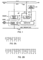
- a control bus 100 is connected to a plurality of access control circuits 20, only one of which is shown.
- the control bus 100 provides for an access control system which regulates access to a common facility.
- the common facility is a data transfer bus 200, to which by a plurality of units are to have controlled access.
- Each of the units is connected to a corresponding one of the access control circuits 20 via request and grant leads and a unit output bus.
- the control bus 100 includes control leads 1 through n and a busy lead 102.
- a source 110 of a unit address is connected via a bus 22 to inputs of a driver circuit 21 and to inputs of a comparator circuit 24.
- Outputs of the driver circuit 21 are connected to the leads 1 through n respectively and to inputs of the comparator circuit 24 via a bus 23.
- An output of the comparator circuit 24 is the origin of a grant lead 25.
- the output is connected via the grant lead 25 to an enable input EN of a driver circuit 27, and to an input of a request logic circuit 26.
- the request lead is also connected to an input of the request logic circuit 26.
- the request logic circuit 26 includes an output connected to an enable input EN of the driver circuit 21.
- the unit output bus is connected to inputs of a driver circuit 27 which includes outputs connected to the data transfer bus 200.
- the driver circuit 27 also includes an enable input EN connected to the grant lead 25.
- An access control circuit as illustrated in figure 1 is connected at any one of unit location positions 0 through 7 in figure 2a.
- Each unit location position is associated with three terminals for providing the connection to leads 1 through 3, corresponding to the leads 1 through n in figure 1.
- Each of the leads except for the nth lead is discontinuous such that it consists of 2 n /2 x segments, where x is the identifying number of the lead. Each segment includes at most 2 x terminals.
- Figure 2b illustrates an expansion to four leads in the control bus.
- the control bus 100 may be in any convenient form. It is particularly useful in a back plane or middle plane structure including an insulating substrate which carries the leads of the control bus and the data transfer bus for connection to circuit packages by any of various arrangements well known to persons skilled in hardware design of electronic telephone systems.
- the source of location address 110 although not shown in figures 2a and 2b may also be carried on the insulating substrate in association with each unit location.
- the source 110 is normally hard wire configured to provide binary signal states corresponding to the identity of the connection terminals of the unit location. However a register or the like may be used in combination or in substitution for the hard wire configured source to provide a readily alterable location address.
- Each of the examples includes a clocked set reset flip-flop 30 having a reset input R connected to the grant lead 25, a set input S connected to an output of an AND gate 31 and an output Q connected to the enable input of the driver circuit 21 in figure 1.
- the AND gate 31 includes an input connected to the request lead and an inverting input connected to the busy lead 102.
- a Q output of the flip-flop 30 is also connected to the busy lead via a buffer amplifier 32.
- the Q output of the flip-flop is connected also to an input of an AND gate 33 which includes an output connected to the busy lead 102 and an inverting input connected to the grant lead 25.
- An illustration of a basic operation of the access control circuit 20 does not require the request logic circuit 26 or the busy lead 102, providing that the request lead is connected directly to the EN input of the drive circuit 21.
- the access control circuit 20 is coupled or lodged at a unit location so that the driver 21 is connected to the control bus leads 1, 2 and 3 as illustrated in figure 2a. Clock signal and power are distributed as required, but are not shown.
- Each of the access control circuits is responsive to a request asserted on the request lead by its associated unit to assert its unit location address on the leads 1 through 3 of the control bus. If and when the comparator 24 detects a match between the address on the leads 1 through 3 of the control bus and the address from the source 110, it asserts a grant signal which causes the driver 27 to assert data from the associated circuit unit onto the data transfer bus 200, and at the same time informs the associated circuit unit that it has obtained access to the common facility, in this case the bus 200. If the unit has more data to send, the request signal remains asserted, otherwise it becomes unasserted. Hence circuit units are granted access to the bus 200 on a priority basis, the highest address always having highest priority and the lowest address having the lowest priority.
- Fair access is provided by including the busy lead 102 and the request logic circuit 26.
- the request In the event that a request has been asserted, the request is only registered in the flip-flop 30 via the AND gate 31 if the busy lead 102 is not asserted. If the busy lead 102 is asserted, this indicates that at least one other access control circuit is already waiting for access to the data transfer bus 200.
- the busy lead 102 becomes unasserted all of the access control circuits respond to request signal assertions from their associated units by asserting their respective location addresses via their driver circuits 21 and a busy signal on the busy lead 102. Hence each of the access control circuits which have an access requirement at this instant are subsequently provided with access, before any further access requests are registered and serviced.
- FIG 4. An exemplary sequence of functions of the access control circuit using the request logic circuit of figure 3 is illustrated in figure 4.
- circuit units 1, 4 and 6 each request service.
- each corresponding access control circuit asserts its unique location address onto leads 1 - 3 of the control bus, and also asserts a busy signal on the busy lead 102.
- Each access control unit receives an address during this and each subsequent clock tick as shown opposite the unit locations in figure 3.
- unit 6 gains access, in the next clock tick, unit 4 gains access, and so on until each initially requesting unit has been served.
- unit 3 is shown to be making a request during the third mentioned clock tick. However as the busy lead 102 is asserted, in its corresponding access control unit the flip flop 30 does not register the request. When the busy lead becomes unasserted, the request is registered in the next clock tick by the flip-flop 30. In the following clock tick, unit 3 gains access to the data transfer bus 200 and at the same time a second request from unit 3 is registered. 0n the second following clock tick unit three again gains access to the bus 200.
- Operation of the access control system in accordance with figures 1 and 3 provides a fair allocation of access to the bus 200 among all the circuit units, however at the expense of some lost access time. This occurs because in order for an access request to be registered, the busy bus must be idle or unasserted. This may be of no practical significance in a large system, however in the absence of requests from other units one unit, which might advantageously be given full time access to the bus 200, is limited to access for only half of the time. This is illustrated in figure 4.
- a further improved operation of the access control circuit is achieved with the use of the request logic circuit in figure 5.
- the primary difference between the circuit of figure 3 and figure 5 is that the busy lead 102 becomes asserted by the request logic circuit only during the presence of the registered request while the grant signal is unasserted. The moment an access control circuit generates the grant signal, the busy lead assertion is removed at the same clock tick, not in the following clock tick as was the case in the previous example.
- This improved operation is shown in figure 6 and is in contrast to the otherwise similar illustration of figure 4.
Landscapes
- Engineering & Computer Science (AREA)
- Theoretical Computer Science (AREA)
- Physics & Mathematics (AREA)
- General Engineering & Computer Science (AREA)
- General Physics & Mathematics (AREA)
- Computer Networks & Wireless Communication (AREA)
- Signal Processing (AREA)
- Bus Control (AREA)
- Small-Scale Networks (AREA)
- Data Exchanges In Wide-Area Networks (AREA)
Applications Claiming Priority (2)
| Application Number | Priority Date | Filing Date | Title |
|---|---|---|---|
| CA431062 | 1983-06-23 | ||
| CA431062 | 1983-06-23 |
Publications (2)
| Publication Number | Publication Date |
|---|---|
| EP0130000A2 true EP0130000A2 (fr) | 1985-01-02 |
| EP0130000A3 EP0130000A3 (fr) | 1985-09-18 |
Family
ID=4125535
Family Applications (1)
| Application Number | Title | Priority Date | Filing Date |
|---|---|---|---|
| EP84303823A Withdrawn EP0130000A3 (fr) | 1983-06-23 | 1984-06-06 | Appareil et méthode pour commander l'accès à un dispositif commun par une pluralité d'unités |
Country Status (2)
| Country | Link |
|---|---|
| EP (1) | EP0130000A3 (fr) |
| JP (1) | JPS6016044A (fr) |
Cited By (2)
| Publication number | Priority date | Publication date | Assignee | Title |
|---|---|---|---|---|
| DE3532439A1 (de) * | 1984-09-11 | 1986-04-17 | Ricoh Co., Ltd., Tokio/Tokyo | Mehrfachzugriff-uebertragungsverfahren |
| EP0494372A3 (en) * | 1990-12-31 | 1993-05-19 | Telenorma Gmbh | Method for access control for stations connected on a bus system in communication switching arrangements |
Family Cites Families (5)
| Publication number | Priority date | Publication date | Assignee | Title |
|---|---|---|---|---|
| US3710351A (en) * | 1971-10-12 | 1973-01-09 | Hitachi Ltd | Data transmitting apparatus in information exchange system using common bus |
| US3978451A (en) * | 1975-04-21 | 1976-08-31 | Rca Corporation | Controlling communications between computer devices over common bus |
| GB2060960A (en) * | 1979-10-10 | 1981-05-07 | Magnuson Computer Systems Inc | Data processing apparatus with parallel encoded priority |
| JPS5723131A (en) * | 1980-07-18 | 1982-02-06 | Nippon Telegr & Teleph Corp <Ntt> | Acquisition system for priority right of interruption |
| US4375639A (en) * | 1981-01-12 | 1983-03-01 | Harris Corporation | Synchronous bus arbiter |
-
1984
- 1984-06-06 EP EP84303823A patent/EP0130000A3/fr not_active Withdrawn
- 1984-06-23 JP JP12991884A patent/JPS6016044A/ja active Pending
Cited By (2)
| Publication number | Priority date | Publication date | Assignee | Title |
|---|---|---|---|---|
| DE3532439A1 (de) * | 1984-09-11 | 1986-04-17 | Ricoh Co., Ltd., Tokio/Tokyo | Mehrfachzugriff-uebertragungsverfahren |
| EP0494372A3 (en) * | 1990-12-31 | 1993-05-19 | Telenorma Gmbh | Method for access control for stations connected on a bus system in communication switching arrangements |
Also Published As
| Publication number | Publication date |
|---|---|
| JPS6016044A (ja) | 1985-01-26 |
| EP0130000A3 (fr) | 1985-09-18 |
Similar Documents
| Publication | Publication Date | Title |
|---|---|---|
| US4383315A (en) | Idle time slot seizure and transmission facilities for loop communication system | |
| US4608685A (en) | Packet and circuit switched communications network | |
| US4586175A (en) | Method for operating a packet bus for transmission of asynchronous and pseudo-synchronous signals | |
| EP0203165B1 (fr) | Protocole de mise en file d'attente | |
| US3985962A (en) | Method of information transmission with priority scheme in a time-division multiplex communication system comprising a loop line | |
| US5960001A (en) | Apparatus and method for guaranteeing isochronous data flow on a CSMA/CD network | |
| US5430848A (en) | Distributed arbitration with programmable priorities | |
| KR880002197B1 (ko) | 분할요구버스에 호출을 할당하기 위한 시스템 | |
| US4458314A (en) | Circuitry for allocating access to a demand shared bus | |
| CA1274304A (fr) | Circuit a points de croisement pour commutateurs spatiaux de paquets de donnees | |
| JPH0748739B2 (ja) | 多重アクセス制御方法および該方法を実施する多重アクセス制御システム | |
| JPS611146A (ja) | 情報通信装置 | |
| US4366480A (en) | Demand driven access mechanism | |
| US7450606B2 (en) | Bit slice arbiter | |
| US6163827A (en) | Method and apparatus for round-robin flash channel arbitration | |
| US5128937A (en) | Adaptive bandwidth balancing for distributed queue dual bus networks | |
| US5383186A (en) | Apparatus and method for synchronous traffic bandwidth on a token ring network | |
| US7698485B2 (en) | Round-robin bus protocol | |
| FI83008B (fi) | Foerfarande och anordning foer att vaelja en station fraon en grupp av stationer vilka kommunicerar med en huvudstation. | |
| US5867670A (en) | Self-control type bus arbitration circuit and arbitration method therefor | |
| KR100236948B1 (ko) | 셀 버스 조정 장치 및 방법 | |
| US4376975A (en) | Arbitration controller providing for access of a common resource by a plurality of central processing units | |
| EP0130000A2 (fr) | Appareil et méthode pour commander l'accès à un dispositif commun par une pluralité d'unités | |
| US4634812A (en) | Method of transferring information between microcomputers in a decentralized process control system, particularly for telephone systems | |
| US6654838B1 (en) | Methods for performing bit sensitive parallel bus peer addressing |
Legal Events
| Date | Code | Title | Description |
|---|---|---|---|
| PUAI | Public reference made under article 153(3) epc to a published international application that has entered the european phase |
Free format text: ORIGINAL CODE: 0009012 |
|
| AK | Designated contracting states |
Designated state(s): AT DE FR GB IT NL SE |
|
| PUAL | Search report despatched |
Free format text: ORIGINAL CODE: 0009013 |
|
| AK | Designated contracting states |
Designated state(s): AT DE FR GB IT NL SE |
|
| STAA | Information on the status of an ep patent application or granted ep patent |
Free format text: STATUS: THE APPLICATION IS DEEMED TO BE WITHDRAWN |
|
| 18D | Application deemed to be withdrawn |
Effective date: 19860519 |
|
| RIN1 | Information on inventor provided before grant (corrected) |
Inventor name: GEADAH, YOUSSEF ALFRED |