EP0130003A1 - Elektronischer Kreis für ein vibrierendes Rohrdensimeter - Google Patents
Elektronischer Kreis für ein vibrierendes Rohrdensimeter Download PDFInfo
- Publication number
- EP0130003A1 EP0130003A1 EP84303896A EP84303896A EP0130003A1 EP 0130003 A1 EP0130003 A1 EP 0130003A1 EP 84303896 A EP84303896 A EP 84303896A EP 84303896 A EP84303896 A EP 84303896A EP 0130003 A1 EP0130003 A1 EP 0130003A1
- Authority
- EP
- European Patent Office
- Prior art keywords
- container
- temperature
- electronic
- circuit means
- measuring
- Prior art date
- Legal status (The legal status is an assumption and is not a legal conclusion. Google has not performed a legal analysis and makes no representation as to the accuracy of the status listed.)
- Granted
Links
- 230000010355 oscillation Effects 0.000 claims abstract description 35
- 239000000126 substance Substances 0.000 claims abstract description 25
- 238000000034 method Methods 0.000 claims abstract description 6
- 238000005259 measurement Methods 0.000 claims description 5
- 230000010354 integration Effects 0.000 claims 1
- 239000012530 fluid Substances 0.000 description 8
- 239000003990 capacitor Substances 0.000 description 7
- 230000001419 dependent effect Effects 0.000 description 7
- 238000012544 monitoring process Methods 0.000 description 5
- 230000009969 flowable effect Effects 0.000 description 3
- 230000010358 mechanical oscillation Effects 0.000 description 3
- 238000010276 construction Methods 0.000 description 2
- 238000001739 density measurement Methods 0.000 description 2
- 238000010586 diagram Methods 0.000 description 2
- 239000012153 distilled water Substances 0.000 description 2
- 230000005484 gravity Effects 0.000 description 2
- 238000012986 modification Methods 0.000 description 2
- 230000004048 modification Effects 0.000 description 2
- BASFCYQUMIYNBI-UHFFFAOYSA-N platinum Chemical compound [Pt] BASFCYQUMIYNBI-UHFFFAOYSA-N 0.000 description 2
- 238000012546 transfer Methods 0.000 description 2
- XLYOFNOQVPJJNP-UHFFFAOYSA-N water Chemical compound O XLYOFNOQVPJJNP-UHFFFAOYSA-N 0.000 description 2
- 238000005452 bending Methods 0.000 description 1
- 230000003247 decreasing effect Effects 0.000 description 1
- 238000006073 displacement reaction Methods 0.000 description 1
- 230000000694 effects Effects 0.000 description 1
- 239000013013 elastic material Substances 0.000 description 1
- 238000000691 measurement method Methods 0.000 description 1
- 229910052697 platinum Inorganic materials 0.000 description 1
- 238000012545 processing Methods 0.000 description 1
- 230000000717 retained effect Effects 0.000 description 1
- 239000000523 sample Substances 0.000 description 1
- 229910001220 stainless steel Inorganic materials 0.000 description 1
- 239000010935 stainless steel Substances 0.000 description 1
- 238000012360 testing method Methods 0.000 description 1
Images


Classifications
-
- G—PHYSICS
- G01—MEASURING; TESTING
- G01N—INVESTIGATING OR ANALYSING MATERIALS BY DETERMINING THEIR CHEMICAL OR PHYSICAL PROPERTIES
- G01N9/00—Investigating density or specific gravity of materials; Analysing materials by determining density or specific gravity
- G01N9/002—Investigating density or specific gravity of materials; Analysing materials by determining density or specific gravity using variation of the resonant frequency of an element vibrating in contact with the material submitted to analysis
-
- G—PHYSICS
- G01—MEASURING; TESTING
- G01N—INVESTIGATING OR ANALYSING MATERIALS BY DETERMINING THEIR CHEMICAL OR PHYSICAL PROPERTIES
- G01N9/00—Investigating density or specific gravity of materials; Analysing materials by determining density or specific gravity
- G01N9/002—Investigating density or specific gravity of materials; Analysing materials by determining density or specific gravity using variation of the resonant frequency of an element vibrating in contact with the material submitted to analysis
- G01N2009/006—Investigating density or specific gravity of materials; Analysing materials by determining density or specific gravity using variation of the resonant frequency of an element vibrating in contact with the material submitted to analysis vibrating tube, tuning fork
Definitions
- the present invention relates to electronically monitoring the mechanical oscillation characteristics of one or more resonantly vibrating tubes through which flowable substances are passing to determine the density of the substances. Both the temperature and natural period of oscillation of one or more resonantly oscillating tubes are electronically monitored, and the resulting signals are processed to accurately determine the density of the flowing substances independent of temperature variations.
- one end of an elastic container can be rigidly mounted and that the other end of the cantilever mounted container can be oscillated at a resonant angular velocity.
- the resonant angular velocity of oscillation can be calculated by taking the square root of the ratio of the oscillating container's mass to its spring constant about the oscillation axis. Since the mass of the container will vary as the density of the substances flowing through the container varies, monitoring the resonant angular velocity of oscillation of a cantilever mounted container potentially offers a convenient means for measuring the density of flowable substances.
- U-shaped flow tubes with the tube rigidly mounted to a fixed base at the open ends of the U-shaped flow tube.
- a known improvement for the vibrating U-shaped flow tube densimeter is the use of a second cantilever mounted U-shaped flow tube which is positioned along side the first U-shaped flow tube so as to have both U-shaped flow tubes act as the tines of a tuning fork.
- tuning fork operation is substantial attenuation, at the base, of vibration forces associated with the driving of the U-shaped flow tubes at their resonant angular velocities of oscillation.
- the length of the string is dependent on temperature, and, therefore, the tension of the mounted string is varied by temperature. As further disclosed this variation in tension modifies the vibration characteristics of the U-shaped flow tube to compensate for temperature variations.
- Disclosed in United States patent 3,910,101 is an electrical circuit for both monitoring and controlling the oscillation of a fluid filled container. Included as a part of the disclosed circuit is a bridge circuit having as the variable element a temperature dependent sensor. The output of the bridge circuit according to the teachings in United States patent 3,910,101 is used to alter, according to fluctuations in temperature, both the phase and amplitude of the signal driving the oscillation of the fluid filled container.
- United States patent 4,132,110 discloses a mechanical configuration and electrical circuit for determining the density of a fluid passing through an oscillating container without a feedback system for altering the mechanical oscillations of the container as a function of temperature variations.
- the electrical circuitry disclosed in United States patent 4,132,110 for determining fluid density incorporates an oscillator to generate a standard signal from which is subtracted the signal representative of the motion of the oscillating container. According to the disclosures in United States patent 4,132,110, this difference signal is then combined with the signal from a temperature probe to provide a signal proportional to the density of the fluid being measured based on a reference temperature.
- the equation for the density of a substance passing through a resonantly oscillating container is, in general, a relationship where the first term is the oscillating container's spring constant about the oscillation axis, which is a function of temperature, multiplied by the square of the period of oscillation for the oscillating container, with this product being divided by a first constant.
- the second, and last term of this equation is a constant which is subtracted from the first term to give a direct calculation of density.
- the present invention utilizes this analytical description of the mechanics of an oscillating container densimeter to provide an accurate method and electronic circuity for directly determining the density of substances passing through the densimeter.
- the measurement technique of the present invention is dependent on the outputs of two sensors which are mounted either on or in conjunction with the oscillating container.
- One of these sensors can be a velocity sensor, such as an electrical coil and magnet, which monitors the movement of the container and provides a sinusoidal signal corresponding to such movement.
- the other sensor can be a temperature variable resistor mounted on the container or in any other isothermal location relative to the container.
- a signal is provided which corresponds to the movement of the container so that the resonant period of oscillation can be determined; and (2) a signal is provided which corresponds to the temperature of the container so that the temperature coefficient for the spring constant of the container about the oscillation axis can be determined.
- the circuit of the present invention includes two integrators which are connected in series. An input to the first of these integrators is a reference voltage. The outputs of these two integrators are controlled by electronic switches so that the output from the second integrator is a function of the square of the time that the inputted reference voltage is integrated. The duration of time during which the integrators function is determined by the output of the sense coil monitoring the movement of the oscillating container so that the combined output from the integrators is a function of the square of the resonant period of oscillation of the container.
- Controlling the reference voltage inputted to the first integrator is a circuit incorporating a bridge, one arm of the bridge being the temperature variable resistor which is mounted on the container so that as the temperature of the container varies the reference voltage is accordingly varied, and, therefore, the output of the integrators represents a product of a temperature dependent function and the square of the period of oscillation of the resonantly oscillating container.
- the output of the bridge circuit By controlling the output of the bridge circuit, an accurate representation of the variation in the spring constant of the container about the oscillation axis as a function of temperature can be provided to the series integrator circuitry.
- the output of the integrators after passing through a buffer circuitry gives a direct readout of the density of substances passing through the densimeter.
- FIG. 1 a block diagram of the circuit of the present invention is shown in FIG. 1.
- the configuration of densimeter 10 includes the supports 14, the plenums formed by manifolds 16 and end plates 18, and the electromagnetic drive and sensor mechanism 20.
- Such a configuration provides for parallel fluid flow through the two tubes 12, which act as the tines of a tuning fork when vibrated.
- a detailed description of the construction and fluid dynamics associated with this configuration is set forth in detail in pending United States patent application serial number 439,035, filed November 3, 1982 for Parallel Path Coriolis Mass Flow Rate Meter by inventors James E. Smith and Donald Cage.
- electromagnetic drive and sensor mechanism 20 can consist of such known means as a magnet fixed to one of the vibrating tubes 12, and a drive coil along with a sense coil 22 fixed to the other of the vibrating tubes 12.
- a magnet fixed to one of the vibrating tubes 12
- a drive coil along with a sense coil 22 fixed to the other of the vibrating tubes 12.
- W-W bending axes
- sense coil 22 fixed to the other of the vibrating tubes 12.
- the mass of the substance flowing through the vibrating tubes 12 is equal to the product of the density, p, of the substance times the internal volume, V , of the vibrating tubes 12.
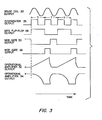
- the circuit of the present invention operates as follows, initially switches Sl and S3 are both closed thereby holding integrator capacitors Cl and C2 in a fully discharged-condition while switches S2 and S4 are both initially open.
- the output of sense coil 22 is fed into comparator 26 which provides a square wave output having a period equal to that of the oscillating tubes 12.
- comparator 26 By feeding the output of comparator 26 into data flip-flop 28 and NOR gate 30, switches Sl and S3 are opened and switch S2 is closed when tubes 12 reach their maximum displacements from their mid-planes of oscillation.
- Integrator capacitor Cl is then charged due to the current supplied from reference voltage source V 1 through resistor Rl. Accordingly, the output of amplifier 32 is a linear ramp, as shown in FIG.
- the circuitry which modifies V B so as to reflect changes due to temperature fluctuations includes bridge 42 and amplifier 44.
- a 100 ohm platinum resistance thermometer has been used for temperature variable resistor 24.
- This temperature variable resistor 24 is attached to one of tubes 12 by methods known in the art to sense temperature changes.
- the resistance changes caused by temperature fluctuations are measured by bridge 42 and amplified by amplifier 44 to produce a substantially linear increasing voltage as the temperature of temperature variable resistor 24 is increased.
- the voltage, V 2 therefore supplies a temperature controlled current to the summing node 46 to modify V B as follows: where K(temp) is effectively a temperature dependent factor.
- Amplifier 48 provides a buffer for hold capacitor C3, and a current proportional to V H is summed with a current set by variable resistor R5 and constant voltage V 3' This current is amplified by amplifier 50 to provide voltage Vp which can be calculated using the following relationship.
- the output voltage, Vp can be scaled by means of resistors R5 and R7 to produce a voltage equivalent to the density or specific gravity of the substance flowing through the resonantly oscillating tubes 12.
- the output voltage, V ⁇ can be measured using known digital voltmeter circuitry.
- the electronic circuit shown in FIG. 1 has been built and tested using a densimeter having twin 1/4 inch 316L stainless steel tubes. To test the accuracy of the electronic circuitry the densimeter tubes were filled with distilled water, and the densimeter was then placed in an oven. At the various temperatures at which data were taken the temperature was allowed to stabilize for thirty minutes before the following data was recorded.
Landscapes
- Physics & Mathematics (AREA)
- Health & Medical Sciences (AREA)
- Life Sciences & Earth Sciences (AREA)
- Chemical & Material Sciences (AREA)
- Analytical Chemistry (AREA)
- Biochemistry (AREA)
- General Health & Medical Sciences (AREA)
- General Physics & Mathematics (AREA)
- Immunology (AREA)
- Pathology (AREA)
- Measuring Volume Flow (AREA)
Applications Claiming Priority (2)
| Application Number | Priority Date | Filing Date | Title |
|---|---|---|---|
| US503179 | 1983-06-10 | ||
| US06/503,179 US4491009A (en) | 1983-06-10 | 1983-06-10 | Electronic circuit for vibrating tube densimeter |
Publications (2)
| Publication Number | Publication Date |
|---|---|
| EP0130003A1 true EP0130003A1 (de) | 1985-01-02 |
| EP0130003B1 EP0130003B1 (de) | 1989-08-16 |
Family
ID=24001036
Family Applications (1)
| Application Number | Title | Priority Date | Filing Date |
|---|---|---|---|
| EP84303896A Expired EP0130003B1 (de) | 1983-06-10 | 1984-06-08 | Elektronischer Kreis für ein vibrierendes Rohrdensimeter |
Country Status (4)
| Country | Link |
|---|---|
| US (1) | US4491009A (de) |
| EP (1) | EP0130003B1 (de) |
| DE (1) | DE3479442D1 (de) |
| DK (1) | DK166049C (de) |
Cited By (3)
| Publication number | Priority date | Publication date | Assignee | Title |
|---|---|---|---|---|
| WO1988002853A1 (en) * | 1986-10-09 | 1988-04-21 | Micro Motion, Inc. | Apparatus and methods for measuring the density of an unknown fluid using a coriolis meter |
| US4876879A (en) * | 1988-08-23 | 1989-10-31 | Ruesch James R | Apparatus and methods for measuring the density of an unknown fluid using a Coriolis meter |
| WO1998002725A1 (en) * | 1996-07-16 | 1998-01-22 | Micro Motion, Inc. | Vibrating tube densimeter |
Families Citing this family (48)
| Publication number | Priority date | Publication date | Assignee | Title |
|---|---|---|---|---|
| US4655075A (en) * | 1984-09-26 | 1987-04-07 | University Of Delaware | Vibrating tube densimeter |
| US4679947A (en) * | 1985-07-16 | 1987-07-14 | Engineering Measurements Co. | Method and apparatus for measuring steam quality |
| US4733569A (en) * | 1985-12-16 | 1988-03-29 | K-Flow Division Of Kane Steel Co., Inc. | Mass flow meter |
| US4716771A (en) * | 1986-02-11 | 1988-01-05 | K-Flow Division Of Kane Steel Co., Inc. | Symmetrical mass flow meter |
| US5271281A (en) * | 1986-10-28 | 1993-12-21 | The Foxboro Company | Coriolis-type mass flowmeter |
| KR960000099B1 (ko) * | 1986-10-28 | 1996-01-03 | 더폭스보로 컴패니 | 코리올리 유형의 질량유량계 |
| US4911020A (en) * | 1986-10-28 | 1990-03-27 | The Foxboro Company | Coriolis-type mass flowmeter circuitry |
| US5343764A (en) * | 1986-10-28 | 1994-09-06 | The Foxboro Company | Coriolis-type mass flowmeter |
| US5050439A (en) * | 1986-10-28 | 1991-09-24 | The Foxboro Company | Coriolis-type mass flowmeter circuitry |
| US5027662A (en) * | 1987-07-15 | 1991-07-02 | Micro Motion, Inc. | Accuracy mass flow meter with asymmetry and viscous damping compensation |
| US4838084A (en) * | 1988-08-30 | 1989-06-13 | Hans Leopold | Density measuring instrument |
| DE4016907C3 (de) * | 1990-05-25 | 1998-06-10 | Krohne Ag | Massendurchflußmeßgerät |
| DE4124296A1 (de) * | 1990-07-28 | 1992-02-06 | Krohne Messtechnik Massametron | Massendurchflussmessgeraet |
| DE4124295A1 (de) | 1991-07-22 | 1993-01-28 | Krohne Ag | Massendurchflussmessgeraet |
| US5295084A (en) * | 1991-10-08 | 1994-03-15 | Micromotion, Inc. | Vibrating tube densimeter |
| DE4224379C2 (de) | 1992-07-06 | 1998-05-20 | Krohne Messtechnik Kg | Massendurchflußmeßgerät |
| DE4423168C2 (de) | 1994-07-04 | 1998-09-24 | Krohne Ag | Massendurchflußmeßgerät |
| DE4435809A1 (de) | 1994-10-07 | 1996-04-11 | Krohne Messtechnik Kg | Meßgerät für strömende Medien |
| US5546814A (en) * | 1994-10-26 | 1996-08-20 | The Foxboro Company | Parallel-flow coriolis-type mass flowmeter with flow-dividing manifold |
| US6077354A (en) * | 1998-10-07 | 2000-06-20 | Chrysler Corporation | Vehicle painting system having a paint recovery mechanism |
| US6748813B1 (en) | 1998-12-08 | 2004-06-15 | Emerson Electric Company | Coriolis mass flow controller |
| US6513392B1 (en) | 1998-12-08 | 2003-02-04 | Emerson Electric Co. | Coriolis mass flow controller |
| US6688176B2 (en) * | 2000-01-13 | 2004-02-10 | Halliburton Energy Services, Inc. | Single tube densitometer |
| US7549319B2 (en) * | 2006-11-16 | 2009-06-23 | Halliburton Energy Services, Inc. | High pressure resonant vibrating-tube densitometer |
| GB2482448B (en) * | 2009-05-20 | 2013-09-11 | Halliburton Energy Serv Inc | Determining fluid density |
| FR2962220B1 (fr) * | 2010-07-02 | 2012-07-27 | Instrumentation Scient De Laboratoire Isl | Procede de mesure precise de la densite d'un echantillon |
| WO2012177241A1 (en) | 2011-06-21 | 2012-12-27 | Halliburton Energy Services, Inc. | Fluid densitometer with temperature sensor to provide temperature correction |
| AU2012379039B2 (en) | 2012-05-03 | 2015-08-20 | Halliburton Energy Services, Inc. | Single magnet fluid densitometer |
| AU2012388776A1 (en) * | 2012-08-28 | 2015-03-05 | Halliburton Energy Services, Inc. | Sensor characterization apparatus, methods, and systems |
| DE102013113689B4 (de) | 2013-12-09 | 2018-02-01 | Endress + Hauser Flowtec Ag | Dichte-Meßgerät |
| DE102013114731A1 (de) | 2013-12-20 | 2015-06-25 | Endress+Hauser Flowtec Ag | Spule |
| CN105849510B (zh) | 2013-12-20 | 2020-12-15 | 恩德斯+豪斯流量技术股份有限公司 | 线圈 |
| WO2016014053A1 (en) * | 2014-07-23 | 2016-01-28 | Halliburton Energy Services, Inc. | Thermal modulated vibrating sensing module for gas molecular weight detection |
| BR112017004986B1 (pt) | 2014-09-18 | 2021-06-15 | Micro Motion, Inc. | Método para indicar contaminação de combustível em um sistema de motor, e, eletrônica de medidor para medidores de fluxo |
| AT516420B1 (de) * | 2014-10-20 | 2016-11-15 | Anton Paar Gmbh | Verfahren und Vorrichtung zur Ermittlung der Dichte eines Fluids |
| WO2016109451A1 (en) | 2014-12-29 | 2016-07-07 | Concentric Meter Corporation | Electromagnetic transducer |
| US10126266B2 (en) | 2014-12-29 | 2018-11-13 | Concentric Meter Corporation | Fluid parameter sensor and meter |
| EP3215812B1 (de) | 2014-12-29 | 2020-10-07 | Concentric Meter Corporation | Fluidparametersensor und -messgerät |
| US10996092B2 (en) | 2016-02-09 | 2021-05-04 | Micro Motion, Inc. | Method and apparatus for modulating a flowpath |
| DE102017121157A1 (de) | 2017-08-09 | 2019-02-14 | Endress+Hauser Flowtec Ag | Spule sowie Meßwandler mit einer solchen Spule |
| DE102017131199A1 (de) | 2017-12-22 | 2019-06-27 | Endress + Hauser Flowtec Ag | Coriolis-Massendurchfluß-Meßgerät |
| CN113242960B (zh) | 2018-12-20 | 2024-05-14 | 恩德斯+豪斯流量技术股份有限公司 | 科里奥利质量流量计 |
| DE102018133117A1 (de) | 2018-12-20 | 2020-06-25 | Endress+Hauser Flowtec Ag | Coriolis-Massendurchfluß-Meßgerät |
| CN113196016B (zh) | 2018-12-21 | 2024-06-21 | 恩德斯+豪斯流量技术股份有限公司 | 具有磁场探测器的科里奥利质量流量计 |
| DE102019133610A1 (de) | 2019-12-09 | 2021-06-10 | Endress + Hauser Flowtec Ag | Vibronisches Meßsystem zum Messen eines Massestroms eines fluiden Meßstoff |
| DE102020127382A1 (de) | 2020-10-16 | 2022-04-21 | Endress+Hauser Flowtec Ag | Verfahren zum Überprüfen eines vibronischen Meßsystems |
| DE102022112523A1 (de) | 2022-05-18 | 2023-11-23 | Endress+Hauser Flowtec Ag | Vibronisches Meßsystem |
| DE102022116111A1 (de) | 2022-06-28 | 2023-12-28 | Endress+Hauser Flowtec Ag | Vibronisches Meßsystem |
Citations (5)
| Publication number | Priority date | Publication date | Assignee | Title |
|---|---|---|---|---|
| US3339400A (en) * | 1963-08-12 | 1967-09-05 | Automation Prod | Mass presence sensing apparatus |
| US3910101A (en) * | 1972-10-25 | 1975-10-07 | Kratky Otto Dr Dr E H | Devices for measuring density |
| US3983744A (en) * | 1974-08-08 | 1976-10-05 | Agar Instrumentation, Inc. | Method and apparatus for measuring the density of a dirty fluid |
| US4132110A (en) * | 1976-07-20 | 1979-01-02 | Kabushikikaisha Yokogawa Denki Seisakusho | Vibration type liquid density meter |
| US4170128A (en) * | 1976-11-29 | 1979-10-09 | Kratky Otto Dr Dr E H | Apparatus for density determination |
Family Cites Families (17)
| Publication number | Priority date | Publication date | Assignee | Title |
|---|---|---|---|---|
| US2943476A (en) * | 1955-08-08 | 1960-07-05 | Simmonds Aerocessories Ltd | Liquid densitometers |
| DE1598084C3 (de) * | 1965-12-21 | 1974-02-21 | Basf Ag, 6700 Ludwigshafen | Vorrichtung zum kontinuierlichen Bestimmen der Wichte von fließfähigen Stoffen |
| GB1207997A (en) * | 1966-10-22 | 1970-10-07 | Siegfried Brockhaus | Device for measuring the density of a fluid |
| GB1315120A (en) * | 1969-07-17 | 1973-04-26 | Solartron Electronic Group | Density measurements |
| US3690147A (en) * | 1969-08-15 | 1972-09-12 | Massachusetts Inst Technology | Torsional vibration densitometer |
| GB1349257A (en) * | 1970-04-24 | 1974-04-03 | Rotron Inc | Mass flow and mass flow rate indication |
| US3677067A (en) * | 1970-08-20 | 1972-07-18 | Itt | Densitometer |
| US3805592A (en) * | 1970-08-20 | 1974-04-23 | Itt | Densitometer |
| US3842655A (en) * | 1971-10-12 | 1974-10-22 | Itt | Fluid density sensing systems |
| US3769500A (en) * | 1972-06-16 | 1973-10-30 | Itt | Function generator and components thereof |
| US3808875A (en) * | 1972-11-24 | 1974-05-07 | Itt | Densitometer and probe therefor |
| US3775597A (en) * | 1972-12-27 | 1973-11-27 | Itt | Fluid density digital computer |
| US3878374A (en) * | 1973-12-10 | 1975-04-15 | Itt | Densitometer |
| US3885140A (en) * | 1973-12-10 | 1975-05-20 | Itt | Densitometer |
| US4048844A (en) * | 1974-09-06 | 1977-09-20 | Andrzej Dunikowski | Electric system of meter for measurements of density of mixtures conveyed in a pipeline |
| US4011746A (en) * | 1976-02-02 | 1977-03-15 | Simmonds Precision Products, Inc. | Liquid density measurement system |
| US4020330A (en) * | 1976-05-03 | 1977-04-26 | International Telephone And Telegraph Corporation | Densitometer |
-
1983
- 1983-06-10 US US06/503,179 patent/US4491009A/en not_active Expired - Lifetime
-
1984
- 1984-06-08 DE DE8484303896T patent/DE3479442D1/de not_active Expired
- 1984-06-08 DK DK281784A patent/DK166049C/da not_active IP Right Cessation
- 1984-06-08 EP EP84303896A patent/EP0130003B1/de not_active Expired
Patent Citations (5)
| Publication number | Priority date | Publication date | Assignee | Title |
|---|---|---|---|---|
| US3339400A (en) * | 1963-08-12 | 1967-09-05 | Automation Prod | Mass presence sensing apparatus |
| US3910101A (en) * | 1972-10-25 | 1975-10-07 | Kratky Otto Dr Dr E H | Devices for measuring density |
| US3983744A (en) * | 1974-08-08 | 1976-10-05 | Agar Instrumentation, Inc. | Method and apparatus for measuring the density of a dirty fluid |
| US4132110A (en) * | 1976-07-20 | 1979-01-02 | Kabushikikaisha Yokogawa Denki Seisakusho | Vibration type liquid density meter |
| US4170128A (en) * | 1976-11-29 | 1979-10-09 | Kratky Otto Dr Dr E H | Apparatus for density determination |
Cited By (3)
| Publication number | Priority date | Publication date | Assignee | Title |
|---|---|---|---|---|
| WO1988002853A1 (en) * | 1986-10-09 | 1988-04-21 | Micro Motion, Inc. | Apparatus and methods for measuring the density of an unknown fluid using a coriolis meter |
| US4876879A (en) * | 1988-08-23 | 1989-10-31 | Ruesch James R | Apparatus and methods for measuring the density of an unknown fluid using a Coriolis meter |
| WO1998002725A1 (en) * | 1996-07-16 | 1998-01-22 | Micro Motion, Inc. | Vibrating tube densimeter |
Also Published As
| Publication number | Publication date |
|---|---|
| EP0130003B1 (de) | 1989-08-16 |
| DK281784D0 (da) | 1984-06-08 |
| US4491009A (en) | 1985-01-01 |
| DK166049B (da) | 1993-03-01 |
| DK281784A (da) | 1984-12-11 |
| DK166049C (da) | 1993-08-02 |
| DE3479442D1 (en) | 1989-09-21 |
Similar Documents
| Publication | Publication Date | Title |
|---|---|---|
| EP0130003B1 (de) | Elektronischer Kreis für ein vibrierendes Rohrdensimeter | |
| RU2235295C2 (ru) | Расходомер кориолиса с прямолинейной трубкой | |
| US4312235A (en) | Sensor and meter for measuring the mass flow of a fluid stream | |
| KR100310988B1 (ko) | 진동튜우브 수단을 갖는 밀도측정장치와 이 장치의 작동방법 | |
| US4470294A (en) | Method and apparatus for simultaneous determination of fluid mass flow rate, mean velocity and density | |
| US4876879A (en) | Apparatus and methods for measuring the density of an unknown fluid using a Coriolis meter | |
| US4372164A (en) | Industrial process control instrument employing a resonant sensor | |
| JP4588293B2 (ja) | 物質の密度により流量に許容できない誤差が生じたときに物質の質量流量を補償する装置及び方法 | |
| US3902365A (en) | Mass flow monitoring system and method | |
| US20080184813A1 (en) | Coriolis Flow Meter and Method for Determining Flow Characteristics | |
| IE42188B1 (en) | Method and apparatus for monitoring the flow of liquid andthe like | |
| US4957005A (en) | Coriolis-type flowmeter | |
| JP2004521319A5 (de) | ||
| CA1165583A (en) | Digital temperature sensor | |
| EP0300301B1 (de) | Einrichtung und Verfahren zum Messen des Massendurchflusses eines Materials, das durch eine schwingende Rohrleitung strömt | |
| US7774150B2 (en) | Meter electronics and methods for determining one or more of a stiffness coefficient or a mass coefficient | |
| Sittel et al. | Method for Determining the Viscoelastic Properties of Dilute Polymer Solutions at Audio‐Frequencies | |
| US3910101A (en) | Devices for measuring density | |
| US7240567B2 (en) | Dynamic response characteristics of flow meters | |
| JPH0126017B2 (de) | ||
| Pulsford | The analysis of binary gas mixtures by a sonic method | |
| JPH0658862A (ja) | 振動式密度計における温度補正方法 | |
| RU2086924C1 (ru) | Вибрационный преобразователь расхода | |
| KR20210034083A (ko) | 유량계의 강성 계수를 검증할 시기를 결정하기 위한 방법 | |
| RU2139508C1 (ru) | Устройство для контроля давления |
Legal Events
| Date | Code | Title | Description |
|---|---|---|---|
| PUAI | Public reference made under article 153(3) epc to a published international application that has entered the european phase |
Free format text: ORIGINAL CODE: 0009012 |
|
| AK | Designated contracting states |
Designated state(s): DE FR GB IT |
|
| 17P | Request for examination filed |
Effective date: 19850607 |
|
| 17Q | First examination report despatched |
Effective date: 19860818 |
|
| D17Q | First examination report despatched (deleted) | ||
| GRAA | (expected) grant |
Free format text: ORIGINAL CODE: 0009210 |
|
| AK | Designated contracting states |
Kind code of ref document: B1 Designated state(s): DE FR GB IT |
|
| REF | Corresponds to: |
Ref document number: 3479442 Country of ref document: DE Date of ref document: 19890921 |
|
| ITF | It: translation for a ep patent filed | ||
| ET | Fr: translation filed | ||
| PLBI | Opposition filed |
Free format text: ORIGINAL CODE: 0009260 |
|
| 26 | Opposition filed |
Opponent name: KROHNE MEBTECHNIK GMBH&CO.KG Effective date: 19900512 |
|
| PLBN | Opposition rejected |
Free format text: ORIGINAL CODE: 0009273 |
|
| STAA | Information on the status of an ep patent application or granted ep patent |
Free format text: STATUS: OPPOSITION REJECTED |
|
| 27O | Opposition rejected |
Effective date: 19920708 |
|
| ITTA | It: last paid annual fee | ||
| REG | Reference to a national code |
Ref country code: GB Ref legal event code: IF02 |
|
| PGFP | Annual fee paid to national office [announced via postgrant information from national office to epo] |
Ref country code: FR Payment date: 20030512 Year of fee payment: 20 |
|
| PGFP | Annual fee paid to national office [announced via postgrant information from national office to epo] |
Ref country code: GB Payment date: 20030516 Year of fee payment: 20 |
|
| PGFP | Annual fee paid to national office [announced via postgrant information from national office to epo] |
Ref country code: DE Payment date: 20030527 Year of fee payment: 20 |
|
| PG25 | Lapsed in a contracting state [announced via postgrant information from national office to epo] |
Ref country code: GB Free format text: LAPSE BECAUSE OF EXPIRATION OF PROTECTION Effective date: 20040607 |
|
| REG | Reference to a national code |
Ref country code: GB Ref legal event code: PE20 |
|
| APAH | Appeal reference modified |
Free format text: ORIGINAL CODE: EPIDOSCREFNO |