EP0130012A2 - Pince - Google Patents
Pince Download PDFInfo
- Publication number
- EP0130012A2 EP0130012A2 EP84303959A EP84303959A EP0130012A2 EP 0130012 A2 EP0130012 A2 EP 0130012A2 EP 84303959 A EP84303959 A EP 84303959A EP 84303959 A EP84303959 A EP 84303959A EP 0130012 A2 EP0130012 A2 EP 0130012A2
- Authority
- EP
- European Patent Office
- Prior art keywords
- clamp
- base
- spring
- bolt
- leaf
- Prior art date
- Legal status (The legal status is an assumption and is not a legal conclusion. Google has not performed a legal analysis and makes no representation as to the accuracy of the status listed.)
- Granted
Links
Images

Classifications
-
- B—PERFORMING OPERATIONS; TRANSPORTING
- B42—BOOKBINDING; ALBUMS; FILES; SPECIAL PRINTED MATTER
- B42F—SHEETS TEMPORARILY ATTACHED TOGETHER; FILING APPLIANCES; FILE CARDS; INDEXING
- B42F5/00—Sheets and objects temporarily attached together; Means therefor; Albums
- B42F5/06—Corner-holding devices, e.g. for photographs
-
- B—PERFORMING OPERATIONS; TRANSPORTING
- B42—BOOKBINDING; ALBUMS; FILES; SPECIAL PRINTED MATTER
- B42F—SHEETS TEMPORARILY ATTACHED TOGETHER; FILING APPLIANCES; FILE CARDS; INDEXING
- B42F15/00—Suspended filing appliances
- B42F15/06—Suspended filing appliances for hanging large drawings or the like
-
- Y—GENERAL TAGGING OF NEW TECHNOLOGICAL DEVELOPMENTS; GENERAL TAGGING OF CROSS-SECTIONAL TECHNOLOGIES SPANNING OVER SEVERAL SECTIONS OF THE IPC; TECHNICAL SUBJECTS COVERED BY FORMER USPC CROSS-REFERENCE ART COLLECTIONS [XRACs] AND DIGESTS
- Y10—TECHNICAL SUBJECTS COVERED BY FORMER USPC
- Y10T—TECHNICAL SUBJECTS COVERED BY FORMER US CLASSIFICATION
- Y10T24/00—Buckles, buttons, clasps, etc.
- Y10T24/20—Paper fastener
- Y10T24/201—Paper fastener with screw threaded or notch engaging securing means
-
- Y—GENERAL TAGGING OF NEW TECHNOLOGICAL DEVELOPMENTS; GENERAL TAGGING OF CROSS-SECTIONAL TECHNOLOGIES SPANNING OVER SEVERAL SECTIONS OF THE IPC; TECHNICAL SUBJECTS COVERED BY FORMER USPC CROSS-REFERENCE ART COLLECTIONS [XRACs] AND DIGESTS
- Y10—TECHNICAL SUBJECTS COVERED BY FORMER USPC
- Y10T—TECHNICAL SUBJECTS COVERED BY FORMER US CLASSIFICATION
- Y10T24/00—Buckles, buttons, clasps, etc.
- Y10T24/44—Clasp, clip, support-clamp, or required component thereof
- Y10T24/44291—Clasp, clip, support-clamp, or required component thereof including pivoted gripping member
- Y10T24/44376—Spring or resiliently biased about pivot
- Y10T24/44385—Distinct spring
- Y10T24/44402—Distinct spring with operator for moving pivoted member
-
- Y—GENERAL TAGGING OF NEW TECHNOLOGICAL DEVELOPMENTS; GENERAL TAGGING OF CROSS-SECTIONAL TECHNOLOGIES SPANNING OVER SEVERAL SECTIONS OF THE IPC; TECHNICAL SUBJECTS COVERED BY FORMER USPC CROSS-REFERENCE ART COLLECTIONS [XRACs] AND DIGESTS
- Y10—TECHNICAL SUBJECTS COVERED BY FORMER USPC
- Y10T—TECHNICAL SUBJECTS COVERED BY FORMER US CLASSIFICATION
- Y10T24/00—Buckles, buttons, clasps, etc.
- Y10T24/44—Clasp, clip, support-clamp, or required component thereof
- Y10T24/44641—Clasp, clip, support-clamp, or required component thereof having gripping member formed from, biased by, or mounted on resilient member
- Y10T24/44684—Clasp, clip, support-clamp, or required component thereof having gripping member formed from, biased by, or mounted on resilient member with operator for moving biased engaging face
- Y10T24/44692—Camming or wedging element
Definitions
- This invention relates to an improved clamp.
- it relates to a clamp for holding one or more sheet articles, such as drawings or maps.
- the clamp of the present invention holds one or more sheet articles and is of the type comprising a pair of jaws, each jaw having an elongate gripping part and an elongate base part, one of said base parts being pivotabl,e about the other base part, a closing means adapted to bring together, in use, the gripping parts in order to hold one or more sheet articles between the gripping parts by causing the pivotable base part to pivot about the other base part.
- An L-shaped leaf spring which provides a biasing pressure against the opposing legs of the clamp is disclosed. Also disclosed is an improved assembly/adjustment bolt.
- One advantageous feature of the spring-biased clamp combination of the present invention is that the use of a thin flat leaf spring to bias the gripping legs of the clamp allows thin sheets of paper, which may number anywhere between one and one hundred sheets, tb be inserted between the gripping legs without fouling their edges against the biasing means.
- the thin spring of the present invention presents no obstacle to the insertion of paper into the clamp.
- Another advantage of the present invention is that the spring is held in place by the same bolt which holds the two separate elongate jaws of the clamp. Attachment of the spring to the lower jaw by means of the bolt results in the bolt itself being tensioned against the lower jaw. This facilitates assembly by keeping the bolt from falling out of the lower jaw when the upper jaw is being put in place. Furthermore, should the wing nut. which holds the clamp jaws together and provides tensioning force, fall out in use. the bolt will not dislodge and become lost within the interior of the clamp mechanism.
- the biasing spring is designed to be capable of retrofitting to existing prior art paper sheet clamps.
- a spring is disclosed which fits between the upper and lower bases of the two jaws of existing clamps and provides its outward biasing force by abutting against the inner wall of the gripping leg of the upper jaw.
- the spring is adapted to be secured by the existing assembly bolts, it may be retrofitted to prior art sheet clamps while allowing such clamps to receive final assembly at only two places.
- the jaws of the clamp are assembled by holding them together, along with the springs, by means of the two assembly bolts.
- the assembly bolts also serve to tension and adjust the clamping action of the clamp when in use.
- Yet another feature of the present invention is an improved head for the assembly bolt.
- the assembly bolts were round headed and the heads were so small as to not contact the projecting flange of the lower base of the clamp. For this reason, the prior art bolts tended to rotate along with the wing nut when a user attempted to tighten the wing nut.
- the improved head of the bolt of the instant invention has at least one flat surface on its otherwise circular circumference. Furthermore, the head is enlarged so that when used in combination with the lower jaw of the clamp the flat surface of the head abuts against a flange on the base, preventing the bolt from turning when the wing nut is tightened.
- Yet another feature of the instant invention is a flangeless stopper which allows the clamp to be removed from a support fitment by a tilting action, the clamp being supported on the fitment by only one flanged member.
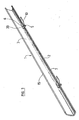
- the clamp comprises a pair of elongate jaws l,la.
- Each jaw has an elongate base 2,2a and an elongate gripping leg 3,3a.
- the jaws l,la are typically made of strips of extruded anodised aluminium.
- the jaws may be of different lengths, depending on the application. 82.5 cm would be a typical length.
- One of the bases is pivotable about the other base.
- the upper base 2a is pivotable about the lower base 2.
- a closing means is provided which is adapted to bring together in use the gripping legs 3,3a to hold one or more sheet articles (not illustrated) between the gripping legs.
- the preferred closing means is a nut 4 which is provided with wings for ease of turning by hand.
- the nut 4 is threaded on a bolt 5 which has a head 6 and which passes through circular holes in the bases 2 and 2a.
- the hole in the pivotable upper base 2a should be larger than the diameter of the bolt 5 to allow for pivotal movement of that base about the bolt 5.
- the head 6 of the bolt 5 abuts a portion of the lower base 2 of jaw 1 so that the bolt 5 will not turn when the nut 4 is tightened.
- One edge of the nut 4 can be flattened as shown to help resist movement.
- the lower base 2 is shown provided with a flange 7 against which the bolt head 6 abuts.
- the clamp is provided with biasing means biased to urge the gripping legs apart.
- the biasing means is preferably a steel leaf spring 10 which is held in place by the bolt 5, which passes through a hole 23 in the spring 10.
- a clip 24 may also be included to hold the bolt 5 and the spring 10 onto the lower base 2.
- the spring 10 acts against the upper jaw la so as to urge the gripping leg 3a away from the gripping leg 3.
- a biasing means is provided for each closing means.
- a handle 12 is attached at or near the centre of the upper base 2a. This enables the clamp and retained sheets to be lifted and moved easily.
- the handle 12 may be formed by of a bent steel rod which is attached to the upper base 2a by screwing; but the handle may be constructed and attached in other ways.
- Attachment means 13,13a are also affixed to the upper base part 2a. These are typically formed of plastics material and are rivetted onto the upper base 2a. They are designed to enable the clamp to be attached to a fitment 25, for instance on a rack, trolley or stand (not illustrated) on which a number of the clamps may be mounted.
- the attachment means 13 shown has an elevated projecting flange 14 which engages with a flange or flanges on the fitment and holds the clamp in place.
- Alternative forms of attachment means may be used, for instance, hooks or eyes.
- Stopper 13a prevents the clamp from slipping forward when attached to the fitment. This stopper could be a knob of cylindrical or other flangeless shape. To remove the clamp from the fitment, the clamp is tilted down at the leading end so the stopper drops underneath the rear of the fitment. and the clamp can be removed by moving in a reverse direction.
- each jaw l,la in cross-section has a flange 7,7a depending from the base 2,2a.
- the gripping legs 3,3a also depend from the base. the gripping legs being substantially at right angles to the bases adjacent the bases, and inclining inwardly so that the far ends 15,15a of the gripping legs 3,3a are substantially underneath the middle of their respective bases 2,2a.
- the depending gripping leg 3a of upper jaw la is longer than the gripping leg 3 of lower jaw 1.
- Base 2a substantially overlaps base 2 and flange 7a contacts base 2, so that the far gripping ends 15 and 15a of the jaws can meet.
- the closing means are operated using hand pressure by tightening the nuts 4,4a causing the pivotable upper base 2a to pivot about lower base 2; flange 7a forming the pivot point.
- This operation is eased by nylon washer 11.
- the downward pressure provided by the tightening of nut 4 thus causes pivoting leg 3a to approach and close on gripping leg 3 at far ends 15,15a.
- Hand tightening nuts 4,4a provides sufficient pressure between gripping legs 3,3a at their far ends 15,15a to hold one or more sheet articles between the jaws, so that the articles will not fall out under their own weight.
- An especially designed leaf spring 10 has been made. It is to be secured to the bolt 5 where it penetrates the inner extrusion lower base 2.
- the leaf spring 10 fits snugly against the inner extrusion wall of leg 3a thus preventing snagging of paper sheets within the clamp.
- the leaf spring 10 causes the pivoting upper jaw la to self-open as wing nut pressure is released. This is an important aspect when one wants to remove sheets from within clamps singly or multiply. In such cases, since one hand is needed to hold the sheets, only one hand is available to loosen the nut 4 and none is available to bias open the jaws l,la.
- the spring 10 operates to provide this bias.
- the spring also contributes to overall positive operation of the clamp when tightening. "The distal end of spring 10 may be bent or rounded in order that it slide freely against the inner surface of gripping leg 3a.
- the leaf spring 10 is also designed to lock the bolt 5 in position so that the flat edge 20 of bolt head 6 abuts the extrusion flange 7. This facilitates assembly - otherwise the bolt 5 tends to drop out.
- the leaf spring 10 shown in Figure 4', consists of a planar upper leaf 21 from which depends a planar lower leaf 22.
- the lower leaf 22 is bent at an angle of about 140° from the upper leaf 21 when the spring 10 is in its resting state of non-compression.
- the spring 10 may be compressed in use to an included angle of about 90° without undergoing permanent deformation.
- the spring 10 is preferably made of 30 gauge spring steel.
- a specially designed wing nut 4,4a is used. This provides a comfortable finger tightening shape so that maximum purchase can be applied to tighten the clamp jaws l,la fully without special tools.
- the flange 7a may be attached to jaw 1, and the steel spring 10 may be replaced by a coiled steel spring or an elastic substance.
- the nut 4 may be replaced by a toggle or cam arrangement connected to a lever or handle to provide the required downward force.
Landscapes
- Gripping Jigs, Holding Jigs, And Positioning Jigs (AREA)
- Wire Bonding (AREA)
- Clamps And Clips (AREA)
- Sheet Holders (AREA)
- Food-Manufacturing Devices (AREA)
Priority Applications (1)
| Application Number | Priority Date | Filing Date | Title |
|---|---|---|---|
| AT84303959T ATE32997T1 (de) | 1983-06-13 | 1984-06-12 | Klemmleiste. |
Applications Claiming Priority (2)
| Application Number | Priority Date | Filing Date | Title |
|---|---|---|---|
| NZ20455083 | 1983-06-13 | ||
| NZ204550 | 1983-06-13 |
Publications (3)
| Publication Number | Publication Date |
|---|---|
| EP0130012A2 true EP0130012A2 (fr) | 1985-01-02 |
| EP0130012A3 EP0130012A3 (en) | 1985-06-05 |
| EP0130012B1 EP0130012B1 (fr) | 1988-03-16 |
Family
ID=19920380
Family Applications (1)
| Application Number | Title | Priority Date | Filing Date |
|---|---|---|---|
| EP84303959A Expired EP0130012B1 (fr) | 1983-06-13 | 1984-06-12 | Pince |
Country Status (8)
| Country | Link |
|---|---|
| US (1) | US4594754A (fr) |
| EP (1) | EP0130012B1 (fr) |
| JP (1) | JPS6024998A (fr) |
| KR (1) | KR850000307A (fr) |
| AT (1) | ATE32997T1 (fr) |
| AU (2) | AU581619B2 (fr) |
| DE (1) | DE3469866D1 (fr) |
| GB (1) | GB2143890A (fr) |
Families Citing this family (5)
| Publication number | Priority date | Publication date | Assignee | Title |
|---|---|---|---|---|
| US5535896A (en) * | 1995-06-23 | 1996-07-16 | Morgan, Sr.; Donald E. | Hanging apparatus for multiple trousers |
| USD393486S (en) | 1996-08-15 | 1998-04-14 | Rod Ernest Orr | Magazine binder clip |
| AT501547B1 (de) * | 2003-03-24 | 2006-11-15 | Peter Weingartner | Klammer zum klemmen von blättern |
| US8326450B2 (en) * | 2004-12-07 | 2012-12-04 | Lockheed Martin Corporation | Method and system for GPS augmentation of mail carrier efficiency |
| US8984735B2 (en) * | 2012-04-23 | 2015-03-24 | Scott Brown | Desk-mounted retainer device for portable sheet clamps |
Family Cites Families (12)
| Publication number | Priority date | Publication date | Assignee | Title |
|---|---|---|---|---|
| CA671574A (en) * | 1963-10-01 | Plan Hold Corporation | Filing device | |
| US855464A (en) * | 1906-11-12 | 1907-06-04 | Charles A Leonard | Harness-hook. |
| US2869210A (en) * | 1955-04-18 | 1959-01-20 | Plan Hold Corp | Friction-type binder |
| US3014258A (en) * | 1960-06-16 | 1961-12-26 | Stacor Equipment Company | Clamping devices |
| US3069737A (en) * | 1960-07-15 | 1962-12-25 | Plan Hold Corp | Two-piece binder clamp |
| US3221892A (en) * | 1964-04-30 | 1965-12-07 | Stacor Corp | Holder for sheet-like material |
| US3364528A (en) * | 1965-08-23 | 1968-01-23 | Plan Hold Corp | Sheet clamps |
| US3308831A (en) * | 1965-10-05 | 1967-03-14 | Mayline Co | Clamp device |
| DE1536695A1 (de) * | 1966-08-19 | 1970-03-05 | Plan Hold Corp | Klammervorrichtung zum Festhalten von Blaettern |
| US3896526A (en) * | 1973-12-26 | 1975-07-29 | Plan Hold Corp | Friction binder having variable clamping forces |
| DE2640438A1 (de) * | 1976-09-08 | 1978-03-09 | Zippel Gmbh & Co Kg Herbert | Vorrichtung zum zusammenschliessen von blattartigem sammelgut |
| GB2017586B (en) * | 1978-01-23 | 1982-06-03 | Brass Lantern Ltd | Sheets or drawings clamping device |
-
1984
- 1984-06-11 US US06/619,179 patent/US4594754A/en not_active Expired - Fee Related
- 1984-06-12 DE DE8484303959T patent/DE3469866D1/de not_active Expired
- 1984-06-12 EP EP84303959A patent/EP0130012B1/fr not_active Expired
- 1984-06-12 AT AT84303959T patent/ATE32997T1/de not_active IP Right Cessation
- 1984-06-12 GB GB08414948A patent/GB2143890A/en not_active Withdrawn
- 1984-06-13 AU AU29338/84A patent/AU581619B2/en not_active Ceased
- 1984-06-13 KR KR1019840003309A patent/KR850000307A/ko not_active Withdrawn
- 1984-06-13 JP JP59121669A patent/JPS6024998A/ja active Pending
-
1988
- 1988-08-11 AU AU20939/88A patent/AU2093988A/en not_active Abandoned
Also Published As
| Publication number | Publication date |
|---|---|
| ATE32997T1 (de) | 1988-04-15 |
| GB8414948D0 (en) | 1984-07-18 |
| DE3469866D1 (en) | 1988-04-21 |
| KR850000307A (ko) | 1985-02-26 |
| GB2143890A (en) | 1985-02-20 |
| AU2093988A (en) | 1988-11-24 |
| JPS6024998A (ja) | 1985-02-07 |
| AU581619B2 (en) | 1989-03-02 |
| EP0130012A3 (en) | 1985-06-05 |
| AU2933884A (en) | 1984-12-20 |
| US4594754A (en) | 1986-06-17 |
| EP0130012B1 (fr) | 1988-03-16 |
Similar Documents
| Publication | Publication Date | Title |
|---|---|---|
| US5961061A (en) | Strap rolling device | |
| US4893801A (en) | Clamp | |
| US5555780A (en) | Roofing washer-dispensing and fastener-driving machine | |
| US6338475B1 (en) | Bar clamp | |
| US6579163B1 (en) | Blade sharpening assembly | |
| US5307713A (en) | Self-aligning wrench | |
| JP3091863B2 (ja) | プレスブレーキ用工具ホルダ | |
| US20030005797A1 (en) | Clamp device | |
| US4307635A (en) | Locking plier and adapter | |
| US4406188A (en) | Nut-holder attachment for open-end wrench | |
| US4833949A (en) | Adjustable open-end wrench | |
| JPH05503882A (ja) | 枢動および滑動ジョーを備えたクランプ | |
| US3947138A (en) | Paper pad clamping fixture | |
| EP0130012B1 (fr) | Pince | |
| US4880221A (en) | Table for holding work pieces for drilling, cutting and the like | |
| US20060123578A1 (en) | Paint roller | |
| US5031782A (en) | Vertical filing system | |
| DE4200924A1 (de) | Klammervorrichtung eines trommelpedals | |
| US4987998A (en) | Retention device for collecting sockets and wrenches | |
| US5469766A (en) | Adjustable spanner wrench | |
| US4836389A (en) | Self-locking cam lever | |
| US5127639A (en) | Adjustable vise | |
| US4925169A (en) | Clamp with fast-acting, one-hand adjustment | |
| US4753427A (en) | Clamp with fast-acting, one-hand adjustment | |
| US6386476B1 (en) | Floor covering removal tool |
Legal Events
| Date | Code | Title | Description |
|---|---|---|---|
| PUAI | Public reference made under article 153(3) epc to a published international application that has entered the european phase |
Free format text: ORIGINAL CODE: 0009012 |
|
| AK | Designated contracting states |
Designated state(s): AT BE CH DE FR GB IT LI LU NL SE |
|
| PUAL | Search report despatched |
Free format text: ORIGINAL CODE: 0009013 |
|
| AK | Designated contracting states |
Designated state(s): AT BE CH DE FR GB IT LI LU NL SE |
|
| 17P | Request for examination filed |
Effective date: 19850717 |
|
| 17Q | First examination report despatched |
Effective date: 19860515 |
|
| RAP1 | Party data changed (applicant data changed or rights of an application transferred) |
Owner name: PLANHORSE INTERNATIONAL (NZ) LIMITED |
|
| GRAA | (expected) grant |
Free format text: ORIGINAL CODE: 0009210 |
|
| AK | Designated contracting states |
Kind code of ref document: B1 Designated state(s): AT BE CH DE FR GB IT LI LU NL SE |
|
| PG25 | Lapsed in a contracting state [announced via postgrant information from national office to epo] |
Ref country code: BE Effective date: 19880316 |
|
| REF | Corresponds to: |
Ref document number: 32997 Country of ref document: AT Date of ref document: 19880415 Kind code of ref document: T |
|
| REF | Corresponds to: |
Ref document number: 3469866 Country of ref document: DE Date of ref document: 19880421 |
|
| ET | Fr: translation filed | ||
| ITF | It: translation for a ep patent filed | ||
| PG25 | Lapsed in a contracting state [announced via postgrant information from national office to epo] |
Ref country code: LU Free format text: LAPSE BECAUSE OF NON-PAYMENT OF DUE FEES Effective date: 19880630 |
|
| PLBE | No opposition filed within time limit |
Free format text: ORIGINAL CODE: 0009261 |
|
| STAA | Information on the status of an ep patent application or granted ep patent |
Free format text: STATUS: NO OPPOSITION FILED WITHIN TIME LIMIT |
|
| 26N | No opposition filed | ||
| PG25 | Lapsed in a contracting state [announced via postgrant information from national office to epo] |
Ref country code: AT Effective date: 19890612 |
|
| PG25 | Lapsed in a contracting state [announced via postgrant information from national office to epo] |
Ref country code: SE Effective date: 19890613 |
|
| PG25 | Lapsed in a contracting state [announced via postgrant information from national office to epo] |
Ref country code: LI Effective date: 19890630 Ref country code: CH Effective date: 19890630 |
|
| PG25 | Lapsed in a contracting state [announced via postgrant information from national office to epo] |
Ref country code: NL Effective date: 19900101 |
|
| NLV4 | Nl: lapsed or anulled due to non-payment of the annual fee | ||
| REG | Reference to a national code |
Ref country code: CH Ref legal event code: PL |
|
| PGFP | Annual fee paid to national office [announced via postgrant information from national office to epo] |
Ref country code: FR Payment date: 19900629 Year of fee payment: 7 |
|
| ITTA | It: last paid annual fee | ||
| PGFP | Annual fee paid to national office [announced via postgrant information from national office to epo] |
Ref country code: DE Payment date: 19900803 Year of fee payment: 7 |
|
| PG25 | Lapsed in a contracting state [announced via postgrant information from national office to epo] |
Ref country code: FR Effective date: 19920228 |
|
| PG25 | Lapsed in a contracting state [announced via postgrant information from national office to epo] |
Ref country code: DE Effective date: 19920401 |
|
| REG | Reference to a national code |
Ref country code: FR Ref legal event code: ST |
|
| PGFP | Annual fee paid to national office [announced via postgrant information from national office to epo] |
Ref country code: GB Payment date: 19930727 Year of fee payment: 10 |
|
| PG25 | Lapsed in a contracting state [announced via postgrant information from national office to epo] |
Ref country code: GB Effective date: 19940612 |
|
| EUG | Se: european patent has lapsed |
Ref document number: 84303959.5 Effective date: 19900418 |
|
| GBPC | Gb: european patent ceased through non-payment of renewal fee |
Effective date: 19940612 |