EP0130017A2 - Elektrischer Steckverbinder für ein Dreileiterkabel und Verfahren zu seinem Zusammenbau - Google Patents
Elektrischer Steckverbinder für ein Dreileiterkabel und Verfahren zu seinem Zusammenbau Download PDFInfo
- Publication number
- EP0130017A2 EP0130017A2 EP84304048A EP84304048A EP0130017A2 EP 0130017 A2 EP0130017 A2 EP 0130017A2 EP 84304048 A EP84304048 A EP 84304048A EP 84304048 A EP84304048 A EP 84304048A EP 0130017 A2 EP0130017 A2 EP 0130017A2
- Authority
- EP
- European Patent Office
- Prior art keywords
- terminal
- ground
- signal
- cable
- housing
- Prior art date
- Legal status (The legal status is an assumption and is not a legal conclusion. Google has not performed a legal analysis and makes no representation as to the accuracy of the status listed.)
- Withdrawn
Links
Images


Classifications
-
- H—ELECTRICITY
- H01—ELECTRIC ELEMENTS
- H01R—ELECTRICALLY-CONDUCTIVE CONNECTIONS; STRUCTURAL ASSOCIATIONS OF A PLURALITY OF MUTUALLY-INSULATED ELECTRICAL CONNECTING ELEMENTS; COUPLING DEVICES; CURRENT COLLECTORS
- H01R12/00—Structural associations of a plurality of mutually-insulated electrical connecting elements, specially adapted for printed circuits, e.g. printed circuit boards [PCB], flat or ribbon cables, or like generally planar structures, e.g. terminal strips, terminal blocks; Coupling devices specially adapted for printed circuits, flat or ribbon cables, or like generally planar structures; Terminals specially adapted for contact with, or insertion into, printed circuits, flat or ribbon cables, or like generally planar structures
-
- H—ELECTRICITY
- H01—ELECTRIC ELEMENTS
- H01R—ELECTRICALLY-CONDUCTIVE CONNECTIONS; STRUCTURAL ASSOCIATIONS OF A PLURALITY OF MUTUALLY-INSULATED ELECTRICAL CONNECTING ELEMENTS; COUPLING DEVICES; CURRENT COLLECTORS
- H01R13/00—Details of coupling devices of the kinds covered by groups H01R12/70 or H01R24/00 - H01R33/00
- H01R13/02—Contact members
- H01R13/20—Pins, blades, or sockets shaped, or provided with separate member, to retain co-operating parts together
-
- H—ELECTRICITY
- H01—ELECTRIC ELEMENTS
- H01R—ELECTRICALLY-CONDUCTIVE CONNECTIONS; STRUCTURAL ASSOCIATIONS OF A PLURALITY OF MUTUALLY-INSULATED ELECTRICAL CONNECTING ELEMENTS; COUPLING DEVICES; CURRENT COLLECTORS
- H01R13/00—Details of coupling devices of the kinds covered by groups H01R12/70 or H01R24/00 - H01R33/00
- H01R13/46—Bases; Cases
- H01R13/502—Bases; Cases composed of different pieces
- H01R13/504—Bases; Cases composed of different pieces different pieces being moulded, cemented, welded, e.g. ultrasonic welding, or swaged together
-
- H—ELECTRICITY
- H01—ELECTRIC ELEMENTS
- H01R—ELECTRICALLY-CONDUCTIVE CONNECTIONS; STRUCTURAL ASSOCIATIONS OF A PLURALITY OF MUTUALLY-INSULATED ELECTRICAL CONNECTING ELEMENTS; COUPLING DEVICES; CURRENT COLLECTORS
- H01R13/00—Details of coupling devices of the kinds covered by groups H01R12/70 or H01R24/00 - H01R33/00
- H01R13/46—Bases; Cases
- H01R13/502—Bases; Cases composed of different pieces
- H01R13/506—Bases; Cases composed of different pieces assembled by snap action of the parts
-
- H—ELECTRICITY
- H01—ELECTRIC ELEMENTS
- H01R—ELECTRICALLY-CONDUCTIVE CONNECTIONS; STRUCTURAL ASSOCIATIONS OF A PLURALITY OF MUTUALLY-INSULATED ELECTRICAL CONNECTING ELEMENTS; COUPLING DEVICES; CURRENT COLLECTORS
- H01R13/00—Details of coupling devices of the kinds covered by groups H01R12/70 or H01R24/00 - H01R33/00
- H01R13/58—Means for relieving strain on wire connection, e.g. cord grip, for avoiding loosening of connections between wires and terminals within a coupling device terminating a cable
-
- H—ELECTRICITY
- H01—ELECTRIC ELEMENTS
- H01R—ELECTRICALLY-CONDUCTIVE CONNECTIONS; STRUCTURAL ASSOCIATIONS OF A PLURALITY OF MUTUALLY-INSULATED ELECTRICAL CONNECTING ELEMENTS; COUPLING DEVICES; CURRENT COLLECTORS
- H01R13/00—Details of coupling devices of the kinds covered by groups H01R12/70 or H01R24/00 - H01R33/00
- H01R13/62—Means for facilitating engagement or disengagement of coupling parts or for holding them in engagement
- H01R13/627—Snap or like fastening
-
- H—ELECTRICITY
- H01—ELECTRIC ELEMENTS
- H01R—ELECTRICALLY-CONDUCTIVE CONNECTIONS; STRUCTURAL ASSOCIATIONS OF A PLURALITY OF MUTUALLY-INSULATED ELECTRICAL CONNECTING ELEMENTS; COUPLING DEVICES; CURRENT COLLECTORS
- H01R13/00—Details of coupling devices of the kinds covered by groups H01R12/70 or H01R24/00 - H01R33/00
- H01R13/648—Protective earth or shield arrangements on coupling devices, e.g. anti-static shielding
- H01R13/658—High frequency shielding arrangements, e.g. against EMI [Electro-Magnetic Interference] or EMP [Electro-Magnetic Pulse]
- H01R13/6591—Specific features or arrangements of connection of shield to conductive members
- H01R13/6592—Specific features or arrangements of connection of shield to conductive members the conductive member being a shielded cable
- H01R13/6593—Specific features or arrangements of connection of shield to conductive members the conductive member being a shielded cable the shield being composed of different pieces
-
- H—ELECTRICITY
- H01—ELECTRIC ELEMENTS
- H01R—ELECTRICALLY-CONDUCTIVE CONNECTIONS; STRUCTURAL ASSOCIATIONS OF A PLURALITY OF MUTUALLY-INSULATED ELECTRICAL CONNECTING ELEMENTS; COUPLING DEVICES; CURRENT COLLECTORS
- H01R4/00—Electrically-conductive connections between two or more conductive members in direct contact, i.e. touching one another; Means for effecting or maintaining such contact; Electrically-conductive connections having two or more spaced connecting locations for conductors and using contact members penetrating insulation
- H01R4/02—Soldered or welded connections
-
- Y—GENERAL TAGGING OF NEW TECHNOLOGICAL DEVELOPMENTS; GENERAL TAGGING OF CROSS-SECTIONAL TECHNOLOGIES SPANNING OVER SEVERAL SECTIONS OF THE IPC; TECHNICAL SUBJECTS COVERED BY FORMER USPC CROSS-REFERENCE ART COLLECTIONS [XRACs] AND DIGESTS
- Y10—TECHNICAL SUBJECTS COVERED BY FORMER USPC
- Y10T—TECHNICAL SUBJECTS COVERED BY FORMER US CLASSIFICATION
- Y10T29/00—Metal working
- Y10T29/49—Method of mechanical manufacture
- Y10T29/49002—Electrical device making
- Y10T29/49117—Conductor or circuit manufacturing
- Y10T29/49174—Assembling terminal to elongated conductor
- Y10T29/49176—Assembling terminal to elongated conductor with molding of electrically insulating material
Definitions
- the present invention relates to electrical connectors ror trilead cable and more particularly to electrical connectors for connecting electrical cables to electrical terminals of a panelboard, circuit board or the like, and to a method of assembly of such connectors.
- trilead cables are used in electrical connectors for connecting the cables to electrical terminals of a panelboard, circuit board or the like.
- One type is a trilead cable of generally rectangut d r configuration in cross-section and having a signal conductor with ground conductors along opposite sides encased in an insulating jacket.
- Another type is a circular shielded trilead cable which includes an outer conductor electrically encircling the ground conductors between the insulated signal conductor and the insulating jacket.
- a further type is a shielded trilead triaxial cable which has a ground wire and braided conductor extending along the insulating jacket and surrounded by an outer insulating jacket.
- Electrical connectors are known to terminate each of these various types of cables, but none is known to terminate all of these cables, to enable contacts of a test probe to be electrically connected to the signal and ground terminals of tightly-packed connectors on a panelboard or circuit board to test the connections and terminations, positively retains the connectors on the panelboard, and has an integral cable strain relief.
- an electrical connector comprises a dielectric housing member in which signal and ground terminal members are secured with contact sections of the terminal members in alignment with respective openings at a front end of the housing member into which a pin terminal and a ground rail of a panelboard extend for electrical connection with the contact sections of the signal and ground terminal members.
- Termination sections of the signal and ground terminal members extend outwardly from a rear end of the housing member for terminating the signal and ground conductors of a cable thereto.
- a securing section is part of the signal terminal member or ground terminal member for securing a section of the cable therein as a cable strain relief.
- Dielectric cover members are latchably secured together onto the housing member and cover the termination sections terminated to the signal and ground conductors and the securing section secured to the cable section thereby engaging the cable as an added cable strain relief.
- the connector has a low profile with terminals in a plane, and a plurality of such connectors may be closely spaced.
- apertures are located in one of the cover members enabling electrical contacts of a probe to extend through the openings and electrically engage the signal and ground terminal members to determine the integrity of the electricál terminations and the electrical connections.
- termination sections and the securing section of the signal and ground terminal members to which the signal and ground conductors are terminated are encapsulated in a profiled molded cover of dielectric material to protect and seal the terminations, maintain the terminal members in spaced and isolated relationship as an electrical terminal assembly, provide additional cable strain relief, and reduce the number of housing and cover members.
- Such electrical terminal assembly is positioned in a rearward passageway of a dielectric housing member with contact sections of the terminal members in alignment with respective openings at a front end of the housing member into which a pin terminal and a ground rail of a panelboard extend for electrical connection with the contact sections of the signal and ground terminal members.
- the housing member passageway includes an aperture enabling electrical contacts of a probe to extend along the profiled dielectric cover material and electrically engage the signal and ground terminal members to determine the integrity of the electrical terminations and the electrical connections.
- the contact section of the signal terminal member is latchably connected onto the pin terminal and can be disconnected therefrom by movement of the housing member away from the pin terminal which releases the signal terminal member therefrom.
- the invention also includes a method of assembling an electrical connector for terminating signal conductor means and ground conductor means of a trilead cable means and electrically connecting same to a pin terminal and a ground rail of a panelboard characterised by the steps of: terminating a signal terminal to said signal conductor means of said cable means and terminating a ground terminal to said ground conductor means; securing a section of said cable with a cable securing means on either said signal terminal or said ground terminal; inserting said signal terminal and said ground terminal substantially in a plane inside a mould means; moulding dielectric cover material around said signal and ground terminals rearward of intermediate sections thereof and around said secured section of said cabl.e means forming a sealed terminal assembly: and inserting said sealed terminal assembly into a rearward passageway of a dielectric housing and securing said assembly therein, such that intermediate and contact sections of said terminals extend along parallel passageways of said housing having openings such that said signal terminal is electrically engageable with a said pin terminal of said panelboard and said ground terminal is
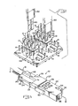
- Electrical panelboard connectors 10 are shown in use in Figure 1 whereby they terminate the signal and ground conductors of electrical cabies 12 and electrically connect them to respective pin terminals 14 arranged in rows in panelboard 16 on opposite sides of elongated channel-shaped ground rails 18.
- Each of electrical panelboard connectors 10 includes a dielectric housing member 20, a signal terminal member 22, a ground terminal member 24, and dielectric cover members 26 and 28.
- Dielectric housing member 20 and cover members 26 and 28 are molded from a suitable plastic material and signal terminal and ground terminal members 22 and 24 are stamped and formed from a suitable metal having the desired spring characteristics.
- Cable 12 is a circular shielded trilead triaxial cable which includes an outer conductor 30 electrically encircling the ground conductors 32 between signal conductor 34 and insulating jacket 36; an insulation sheath 35 covers signal conductor 34.
- a ground conductor 38 and braid 40 extend along insulating jacket 36 and are covered by outer insulating jacket 42. Cable 12 is stripped, as shown in Figure 2, with one of ground conductors 32 being cut off at the end of outer conductor 30 and insulating jacket 36 prior to the stripped end of cable 12 being terminated in signal and ground terminal members 22 and 24.
- Housing member 20 includes parallel passageways 44 and 4 6 in which signal terminal member 22 and ground terminal member 24 are respectively disposed. Passageway 44 is in communication with an opening 48 at the front end of housing member 20. A camming surface 50 is located at the front end of passageway 44. Housing member 20 includes a stepped section 52 spaced from the front surface which has a slot 54 therein that is in communication with passageway 46. Latching apertures 56 and 58 are located in housing member 20 in communication with passageways 46 and 48. A T-shaped member 60 is located on housing member 20 which is to be engaged by a tool (not shown) to facilitate the mounting on and removal from the pin terminals and ground rails of panelboard 16.
- Signal terminal member 22 is of the type disclosed in U.S. Patent Nos. 3,705,376 and 3,796,987 and has a box-shaped section 62 from which extends a lance 64 that is disposed within latching aperture 56 when terminal member 22 is disposed in passageway 44. of housing member 20 latchably securing signal terminal member 22 in position therein, as shown in Figure 7.
- Side members 66 extend outwardly from the sides of section 62 in a forward direction therefrom in parallel relationship to one another and they are connected at their front ends by a bridging member 68 which has a radiussed section 70 struck inwardly therefrom.
- Lugs 72 extend outwardly from the top surfaces of side members 66 opposite one another and they are bent into engagement with a flat section 74 of spring member 76 which engages the top surfaces of side members 66 and is maintained in engagement therewith.
- Recesses 78 are located in flat section 74 in which lugs 72 are disposed to prevent spring member 76 from moving back and forth along side members 66.
- a profiled spring section or latching means 80 is located at the front end of spring member 76 and extends across the front end of terminal member 22.
- An elongated aperture 82 located in spring section 80 in alignment with opening 48 to permit pin terminal 14 to have access to the receptacle section of terminal member 22 through aperture 82, as shown in Figure 8.
- Leaf spring contact member 84 is cantilevered outwardly from the bottom of box-shaped section 62 in a direction toward bridging member 68 and terminates with a radiussed front end 86 spaced forwardly from radiussed section 70.
- An L-shaped terminating section 88 extends rearwardly from box-shaped section 62 and outwardly from the rear end of housing member 20 and it has a projection 90 in which a channel 92 is formed by spaced protrusions 94.
- Ground terminal member 24 has a box-shaped section 96 from which is struck a lance 98 for disposition in latching aperture 58 to latchably secure terminal member 24 in passageway 46 of housing member 20, as shown in Figures 4 and 5.
- Leaf spring contact members 100 are cantilevered respectively from the sides of section 96 in a direction toward each other and they have radiussed front ends 102 disposed within slot 54, as shown in Figure 4, with radiussed front ends 102 electrically engaging a leg of ground rail 18 through slot 54, as shown in Figure 5.
- L-shaped terminating section 104 extends rearwardly from box-shaped section 96 and outwardly from housing member 20 and has a projection 106 in which channels 108 and 110 are formed by protrusions 112.
- a cable securing strain relief section 114 extends outwardly from projection 106 and it includes C-shaped sidewalls 116 and a forwardly directed projection 118 struck from the bottom wall of strain relief section 114.
- ground conductors 32 is cut off at the front end of outer conductor 3 0 and insulating jacket 36. With ground conductor 38 disposed under insulating jacket 36, insulating jacket 36 is forced between C-shaped sidewalls 116 and into engagement with forwardly directed projections 118 thereby providing a strain relief for cable 12 in strain relief section 114.
- Ground conductors 32 and 38 are positioned in channels 110 and 108 while signal conductor 34 is positioned in channel 92 and these conductors are welded or soldered in position therein. As can be discerned from Figure 7, C-shaped sidewalls 116 and forwardly-directed projection 118 bite into insulating jacket 36 thereby forming a strain relief for cable 12.
- Cover member 28 has a relief area 120 along the inside surface at the front end thereof which extends along an undercut section 122 along the outside surface of housing member 20 at the rear end thereof.
- Profiled recess 124 receives therein terminating 88 of signal terminal member 22 while profiled recess 126 receives terminating section 104 and strain relief section 114 of ground terminal member 24 therein.
- a channel 128 extends between recesses 124 and 126 and receives therein insulation sheath 35 surrounding signal conductor 34.
- Projections 130 extend outwardly from an outer end of recess 126 for engagement with outer insulating jacket 42 of cable 12 when disposed therein to provide additional strain relief.
- Latching projections 132 are located in recesses 134 in the sides of cover member 28.
- An opening 136 has a latching projection 138 therein, as shown in Figures 4 and 5.
- Cover member 26 includes flexible latching members 140 which latchably engage onto latching projections 132 and 138 thereby latchably securing cover member 26 to cover member 28.
- Cover member 26 also includes a relief area 142 that extends along undercut section 122 of housing member 20.
- Projections 144 are located on the inside surface of housing member 26 to engage respectively insulating jacket 36 to maintain it in position in C-shaped sidewalls 116 and to engage outer insulating jacket 42 in conjunction with projections 130 to form a strain relief thereon.
- Openings 146 are located on each side of a rib 148 of cover member 26, openings 146 being in alignment with respective terminal members 22 and 24 so that contact members 150 of a probe 152 can be electrically connected with terminal members 22 and 24 to check the terminations and connections thereof while connectors 10 are in position on panelboard 16, as shown in Figure 1.
- Sections 62 and 96 of terminal members 22 and 24 have beveled surfaces 154 to facilitate the positioning of contact members 150 into engagement with projections 156 so that the contact members 150 are disposed between projections 156 and the inside surface of housing member 20.
- housing member 20 When housing member 20 is moved to cam spring section 80 free of pin terminal 14 via camming surface 50, undercut section 122 of housing member 20 moves along and relative to relief areas 120 and 142 of cover members 28 and 26.
- Figure 9 shows ferrule sections 158 and 160 of signal terminal member 22 and ground terminal member 24 which are crimped onto signal conductor 34 and ground conductors 32 and 28.
- Ferrule sections 162 and 164 of terminal members 22 and 24 also are crimped onto insulation sheath 35 and insulating jacket 36 and ground conductor 38.
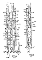
- Figure 10 illustrates an alternate embodiment of the present invention whereby a single molded dielectric housing part is required instead of a tripartite housing.
- Terminated terminals 222 and 224 are positioned in a mold (not shown) and injectable insulating material in a hot flowable condition is injected into the mold forming a profiled dielectric cover 320, as shown in Figures 10, 12 and 13, which entirely encapsulates the terminations of conductors 34', 32' and 38' in terminating members 292, 310 and 308 and the section of cable 12' in strain relief section 116' including a section 36' of cable 12', as shown in Figures 10, 12 and 13.
- the cover 320 is formed into a substantially rigid condition after cooling thereby forming an electrical terminal assembly that is insertable along and disposed in passageway 322 of housing member 220 with the uncovered sections of terminals 222 and 224 being disposed in passageways 44' and 46' and latched therein via lances 64' and 98' disposed in latching apertures 56' and 58'.
- the electrical terminal assembly is entirely disposed within the passageways 44', 46' and 322 which are in communication.
- slotted terminating members 292, 310 and 308 are usable on signal and ground terminals respectively.
- Terminating members 292, 308 and 310 can be in the form of crimping ferrules crimped onto conductors 32', 34' and 38'.
- the profiled dielectric cover 320 maintains the terminals 222 and 224 in proper spaced relationship, seals the terminations and adds additional strain relief to strain relief section 116'.
- a one-piece housing member 220 is used to completely cover the electrical terminal assembly when latchably secured therein. Housing member 220 is movable relative to the electrical terminal assembly to move camming surface 50' in engagement with spring section 80' to remove connector 210 from pin terminal 14' and ground rail 18'.
- Passageway 322 of housing member 220 includes a T-shaped opening 324, as shown in Figures 11 and 13.
- Contact members 150' of electrical probe 152' extend along opening 324 and cover 320 and make electrical contact with terminals 222 and 224 between cover member 220 and projections 130' and 132' on sections 62' and 96' of terminals 222 and 224.
- Probe 152' checks the terminations and connections of terminals 222 and 224 while connectors 210 are in position on panelboard 16', as shown in Figure 11.
- an electrical panelboard connector of simplified construction for terminating electrical conductors of a multiconductor cable to terminating sections of signal and ground electrical terminals which are formed into an electrical terminal assembly by a molded dielectric cover that covers and seals the terminating sections and strain relief section of the terminals, provides additional strain relief, and maintains the terminals in spaced and isolated relationship so that the electrical terminal assembly is secured in a passageway of a dielectric housing member with contact sections of the terminals being electrically connectable to a pin terminal and ground rail of a panelboard through openings in the front end of the housing member in alignment with the contact sections of the terminals.
Landscapes
- Multi-Conductor Connections (AREA)
- Connector Housings Or Holding Contact Members (AREA)
Applications Claiming Priority (4)
| Application Number | Priority Date | Filing Date | Title |
|---|---|---|---|
| US506964 | 1983-06-23 | ||
| US06/506,964 US4491381A (en) | 1983-06-23 | 1983-06-23 | Electrical panelboard connector |
| US06/523,202 US4556275A (en) | 1983-06-23 | 1983-08-15 | Electrical panelboard connector |
| US523202 | 1983-08-15 |
Publications (2)
| Publication Number | Publication Date |
|---|---|
| EP0130017A2 true EP0130017A2 (de) | 1985-01-02 |
| EP0130017A3 EP0130017A3 (de) | 1985-11-21 |
Family
ID=27055656
Family Applications (1)
| Application Number | Title | Priority Date | Filing Date |
|---|---|---|---|
| EP84304048A Withdrawn EP0130017A3 (de) | 1983-06-23 | 1984-06-15 | Elektrischer Steckverbinder für ein Dreileiterkabel und Verfahren zu seinem Zusammenbau |
Country Status (3)
| Country | Link |
|---|---|
| US (1) | US4556275A (de) |
| EP (1) | EP0130017A3 (de) |
| BR (1) | BR8402878A (de) |
Cited By (6)
| Publication number | Priority date | Publication date | Assignee | Title |
|---|---|---|---|---|
| EP0198218A3 (de) * | 1985-04-09 | 1988-10-05 | Allied Corporation | Koaxialkabelendstück |
| EP0337660A1 (de) * | 1988-04-14 | 1989-10-18 | The Whitaker Corporation | Steckverbinder zum Entriegeln von leitenden Elementen von leitenden Stiften |
| EP0405454A3 (en) * | 1989-06-27 | 1991-03-27 | Amp Incorporated | Coaxial contact element |
| EP0393695A3 (de) * | 1989-04-21 | 1991-07-24 | W.L. Gore & Associates GmbH | Steckverbindergehäuse |
| GB2286731A (en) * | 1991-07-05 | 1995-08-23 | Mod Tap W Corp | Electrical connection system |
| AU679386B2 (en) * | 1991-07-05 | 1997-06-26 | Mod-Tap W Corporation | Electrical connection system |
Families Citing this family (20)
| Publication number | Priority date | Publication date | Assignee | Title |
|---|---|---|---|---|
| US4681382A (en) * | 1985-12-20 | 1987-07-21 | Amp Incorporated | Electrical connector for transmission cable |
| US4703983A (en) * | 1986-02-07 | 1987-11-03 | Edco, Inc. | Apparatus for grounding an electronic module coupled to a terminal connecting block |
| US4897046A (en) * | 1986-10-03 | 1990-01-30 | Minnesota Mining And Manufacturing Company | Shielded connector system for coaxial cables |
| US4964814A (en) * | 1986-10-03 | 1990-10-23 | Minnesota Mining And Manufacturing Co. | Shielded and grounded connector system for coaxial cables |
| US4867707A (en) * | 1987-10-19 | 1989-09-19 | W. L. Gore & Associates, Inc. | Coaxial shield integrated contact connector assembly |
| US5217388A (en) * | 1991-04-04 | 1993-06-08 | Heyco Stamped Products, Inc. | Wire safety crimp |
| US5176545A (en) * | 1991-04-04 | 1993-01-05 | Heyco Stamped Products, Inc. | Wire safety crimp |
| GB2255863B (en) * | 1991-05-17 | 1995-05-03 | Minnesota Mining & Mfg | Connector for coaxial cables |
| US5197904A (en) * | 1992-09-04 | 1993-03-30 | Michael Gold | Connector for coaxially shielded cables |
| US5295860A (en) * | 1992-10-15 | 1994-03-22 | Ford Motor Company | Integral battery cable solenoid connector |
| US5480327A (en) * | 1994-05-24 | 1996-01-02 | The Whitaker Corporation | Electrical connector for cable |
| USD432988S (en) * | 1999-01-28 | 2000-10-31 | Japan Solderless Terminal Mfg. Co., Ltd. | Connector housing |
| US6220890B1 (en) * | 1999-03-25 | 2001-04-24 | Illinois Tool Works Inc. | Electrical switch connector assembly |
| DE19921132C1 (de) * | 1999-05-07 | 2001-01-11 | Neutrik Ag Schaan | Kabelstecker für elektrische Verbindungen |
| CN102823073A (zh) | 2010-02-01 | 2012-12-12 | 3M创新有限公司 | 电连接器和组件 |
| WO2012050628A1 (en) * | 2010-10-13 | 2012-04-19 | 3M Innovative Properties Company | Electrical connector assembly and system |
| JP5630365B2 (ja) * | 2011-04-13 | 2014-11-26 | オムロン株式会社 | コネクタ用接続端子およびそれを用いたコネクタ |
| EP2991172B1 (de) * | 2014-08-27 | 2021-01-13 | TE Connectivity Germany GmbH | Fahrzeugkabelanordnung |
| JP7353035B2 (ja) * | 2018-12-26 | 2023-09-29 | スリーエム イノベイティブ プロパティズ カンパニー | 積層型ワイヤマウントウェハコネクタ及びコネクタアセンブリ |
| EP3797962A1 (de) * | 2019-09-30 | 2021-03-31 | Siemens Aktiengesellschaft | Gehäuse eines elektronikmoduls und dessen herstellung |
Family Cites Families (11)
| Publication number | Priority date | Publication date | Assignee | Title |
|---|---|---|---|---|
| CA669608A (en) * | 1963-09-03 | H. Gardener Reginald | Encapsulating electrical components | |
| BE621357A (de) * | 1960-01-04 | |||
| US3533044A (en) * | 1968-06-17 | 1970-10-06 | Ibm | Electrical connecting device |
| US3654589A (en) * | 1969-09-16 | 1972-04-04 | Ibm | Electrical connector |
| US3673542A (en) * | 1970-06-17 | 1972-06-27 | Ibm | Connector assembly with tine skewing housing |
| US3705376A (en) * | 1970-11-25 | 1972-12-05 | Amp Inc | Connector with releasable spring contact and releasing tool |
| US3796987A (en) * | 1972-06-09 | 1974-03-12 | Amp Inc | Electrical receptacle and connector |
| US3864010A (en) * | 1973-01-30 | 1975-02-04 | Amp Inc | Pre-loaded electrical connecting device |
| US3874764A (en) * | 1973-10-31 | 1975-04-01 | Amp Inc | Lead assembly |
| US4040703A (en) * | 1975-09-05 | 1977-08-09 | Amp Incorporated | Tri-lead cable connector |
| US4277124A (en) * | 1979-10-01 | 1981-07-07 | Amp Incorporated | Connector having wire-in-slot connecting means and crimped strain relief |
-
1983
- 1983-08-15 US US06/523,202 patent/US4556275A/en not_active Expired - Fee Related
-
1984
- 1984-06-13 BR BR8402878A patent/BR8402878A/pt not_active IP Right Cessation
- 1984-06-15 EP EP84304048A patent/EP0130017A3/de not_active Withdrawn
Cited By (8)
| Publication number | Priority date | Publication date | Assignee | Title |
|---|---|---|---|---|
| EP0198218A3 (de) * | 1985-04-09 | 1988-10-05 | Allied Corporation | Koaxialkabelendstück |
| EP0337660A1 (de) * | 1988-04-14 | 1989-10-18 | The Whitaker Corporation | Steckverbinder zum Entriegeln von leitenden Elementen von leitenden Stiften |
| EP0393695A3 (de) * | 1989-04-21 | 1991-07-24 | W.L. Gore & Associates GmbH | Steckverbindergehäuse |
| EP0405454A3 (en) * | 1989-06-27 | 1991-03-27 | Amp Incorporated | Coaxial contact element |
| GB2286731A (en) * | 1991-07-05 | 1995-08-23 | Mod Tap W Corp | Electrical connection system |
| GB2286731B (en) * | 1991-07-05 | 1995-11-29 | Mod Tap W Corp | Electrical connection system |
| AU679386B2 (en) * | 1991-07-05 | 1997-06-26 | Mod-Tap W Corporation | Electrical connection system |
| EP0685905A3 (de) * | 1991-07-05 | 1997-11-19 | Mod-Tap W. Corp. | Elektrisches Verbindersystem |
Also Published As
| Publication number | Publication date |
|---|---|
| BR8402878A (pt) | 1985-05-21 |
| US4556275A (en) | 1985-12-03 |
| EP0130017A3 (de) | 1985-11-21 |
Similar Documents
| Publication | Publication Date | Title |
|---|---|---|
| US4556275A (en) | Electrical panelboard connector | |
| US4491381A (en) | Electrical panelboard connector | |
| US4653825A (en) | Shielded electrical connector assembly | |
| US5445538A (en) | Electrical connector strain relief | |
| EP0072063B1 (de) | Zwei- oder dreireihiger Koaxialkabelverbinder | |
| EP0570181B1 (de) | Elektrischer Verbinder für Hochfrequenz | |
| US5855493A (en) | Electrical connector strain relief with shield ground for multiple cables | |
| KR890004498B1 (ko) | 잭-플러그 조립체 | |
| EP0735612B1 (de) | Elektrischer Verbinder mit verbesserter Leiterhalterung und Schirmung | |
| EP0118168B2 (de) | Elektrischer Steckverbinder und Steckdose dafür | |
| US5372513A (en) | Electrical connector with cable shield ground clip | |
| US4516825A (en) | Modular connector for terminating EMI/RFI shielded cordage | |
| EP0624928B1 (de) | Abgeschirmte elektrische Verbinderanordnung | |
| JPH06203893A (ja) | コネクタ | |
| US5564940A (en) | Electrical connector having a conductor holding block | |
| US4537459A (en) | Jack for EMI/RFI shield terminating modular plug connector | |
| US5083934A (en) | Electrical connector system | |
| EP0131425B1 (de) | Modulartiger Verbinder für den Anschluss von gegen elektromagnetische Interferenz und Radiointerferenz abgeschirmten Leitungen und damit angeschlossene Schnur | |
| US5681180A (en) | Conductor holding block for an electrical connector | |
| US6234840B1 (en) | Shield connector | |
| US4737888A (en) | Receptacle assembly and mounting bracket for circuit board connections | |
| EP0211496A1 (de) | Doppelreihiger elektrischer Verbinder | |
| US5405268A (en) | Vertically aligned electrical connector components | |
| EP0653804B1 (de) | Elektrischer Verbinder mit Leiterhalterung | |
| EP0852832A1 (de) | Elektrischer verbinder mit zugentlastung und abschirmung für mehrleiterkabeln |
Legal Events
| Date | Code | Title | Description |
|---|---|---|---|
| PUAI | Public reference made under article 153(3) epc to a published international application that has entered the european phase |
Free format text: ORIGINAL CODE: 0009012 |
|
| AK | Designated contracting states |
Designated state(s): BE DE FR GB IT NL |
|
| PUAL | Search report despatched |
Free format text: ORIGINAL CODE: 0009013 |
|
| AK | Designated contracting states |
Designated state(s): BE DE FR GB IT NL |
|
| 17P | Request for examination filed |
Effective date: 19860509 |
|
| 17Q | First examination report despatched |
Effective date: 19870804 |
|
| STAA | Information on the status of an ep patent application or granted ep patent |
Free format text: STATUS: THE APPLICATION HAS BEEN WITHDRAWN |
|
| 18W | Application withdrawn |
Withdrawal date: 19881001 |
|
| RIN1 | Information on inventor provided before grant (corrected) |
Inventor name: STAHL, DANIEL EUGENE Inventor name: HAMSHER, WILBUR ARTHUR, JR. |