EP0130101B1 - Fernbedientes elektrisches Schloss - Google Patents
Fernbedientes elektrisches Schloss Download PDFInfo
- Publication number
- EP0130101B1 EP0130101B1 EP84401132A EP84401132A EP0130101B1 EP 0130101 B1 EP0130101 B1 EP 0130101B1 EP 84401132 A EP84401132 A EP 84401132A EP 84401132 A EP84401132 A EP 84401132A EP 0130101 B1 EP0130101 B1 EP 0130101B1
- Authority
- EP
- European Patent Office
- Prior art keywords
- bolt
- lock
- ball
- slot
- plate
- Prior art date
- Legal status (The legal status is an assumption and is not a legal conclusion. Google has not performed a legal analysis and makes no representation as to the accuracy of the status listed.)
- Expired
Links
- 238000005096 rolling process Methods 0.000 claims description 5
- 230000009471 action Effects 0.000 claims description 2
- 230000009347 mechanical transmission Effects 0.000 claims description 2
- 230000001747 exhibiting effect Effects 0.000 claims 3
- 238000006073 displacement reaction Methods 0.000 claims 1
- 238000009432 framing Methods 0.000 claims 1
- 230000001483 mobilizing effect Effects 0.000 claims 1
- 239000002184 metal Substances 0.000 description 6
- 206010010904 Convulsion Diseases 0.000 description 5
- 230000008859 change Effects 0.000 description 4
- 210000002445 nipple Anatomy 0.000 description 4
- 230000005540 biological transmission Effects 0.000 description 3
- 125000006850 spacer group Chemical group 0.000 description 3
- 230000000903 blocking effect Effects 0.000 description 2
- 238000011161 development Methods 0.000 description 2
- 230000018109 developmental process Effects 0.000 description 2
- 229910001369 Brass Inorganic materials 0.000 description 1
- 230000002426 anti-panic effect Effects 0.000 description 1
- 239000010951 brass Substances 0.000 description 1
- 230000015556 catabolic process Effects 0.000 description 1
- 230000001419 dependent effect Effects 0.000 description 1
- 230000009977 dual effect Effects 0.000 description 1
- 230000008439 repair process Effects 0.000 description 1
- 230000007704 transition Effects 0.000 description 1
Images

Classifications
-
- E—FIXED CONSTRUCTIONS
- E05—LOCKS; KEYS; WINDOW OR DOOR FITTINGS; SAFES
- E05B—LOCKS; ACCESSORIES THEREFOR; HANDCUFFS
- E05B47/00—Operating or controlling locks or other fastening devices by electric or magnetic means
- E05B47/02—Movement of the bolt by electromagnetic means; Adaptation of locks, latches, or parts thereof, for movement of the bolt by electromagnetic means
- E05B47/026—Movement of the bolt by electromagnetic means; Adaptation of locks, latches, or parts thereof, for movement of the bolt by electromagnetic means the bolt moving rectilinearly
-
- E—FIXED CONSTRUCTIONS
- E05—LOCKS; KEYS; WINDOW OR DOOR FITTINGS; SAFES
- E05B—LOCKS; ACCESSORIES THEREFOR; HANDCUFFS
- E05B15/00—Other details of locks; Parts for engagement by bolts of fastening devices
- E05B15/02—Striking-plates; Keepers; Bolt staples; Escutcheons
- E05B15/0205—Striking-plates, keepers, staples
-
- E—FIXED CONSTRUCTIONS
- E05—LOCKS; KEYS; WINDOW OR DOOR FITTINGS; SAFES
- E05B—LOCKS; ACCESSORIES THEREFOR; HANDCUFFS
- E05B17/00—Accessories in connection with locks
- E05B17/007—Devices for reducing friction between lock parts
-
- E—FIXED CONSTRUCTIONS
- E05—LOCKS; KEYS; WINDOW OR DOOR FITTINGS; SAFES
- E05B—LOCKS; ACCESSORIES THEREFOR; HANDCUFFS
- E05B47/00—Operating or controlling locks or other fastening devices by electric or magnetic means
- E05B47/0001—Operating or controlling locks or other fastening devices by electric or magnetic means with electric actuators; Constructional features thereof
- E05B47/0002—Operating or controlling locks or other fastening devices by electric or magnetic means with electric actuators; Constructional features thereof with electromagnets
-
- E—FIXED CONSTRUCTIONS
- E05—LOCKS; KEYS; WINDOW OR DOOR FITTINGS; SAFES
- E05B—LOCKS; ACCESSORIES THEREFOR; HANDCUFFS
- E05B47/00—Operating or controlling locks or other fastening devices by electric or magnetic means
- E05B2047/0084—Key or electric means; Emergency release
-
- E—FIXED CONSTRUCTIONS
- E05—LOCKS; KEYS; WINDOW OR DOOR FITTINGS; SAFES
- E05B—LOCKS; ACCESSORIES THEREFOR; HANDCUFFS
- E05B47/00—Operating or controlling locks or other fastening devices by electric or magnetic means
- E05B47/0001—Operating or controlling locks or other fastening devices by electric or magnetic means with electric actuators; Constructional features thereof
- E05B47/0002—Operating or controlling locks or other fastening devices by electric or magnetic means with electric actuators; Constructional features thereof with electromagnets
- E05B47/0003—Operating or controlling locks or other fastening devices by electric or magnetic means with electric actuators; Constructional features thereof with electromagnets having a movable core
- E05B47/0004—Operating or controlling locks or other fastening devices by electric or magnetic means with electric actuators; Constructional features thereof with electromagnets having a movable core said core being linearly movable
-
- E—FIXED CONSTRUCTIONS
- E05—LOCKS; KEYS; WINDOW OR DOOR FITTINGS; SAFES
- E05B—LOCKS; ACCESSORIES THEREFOR; HANDCUFFS
- E05B65/00—Locks or fastenings for special use
- E05B65/10—Locks or fastenings for special use for panic or emergency doors
Definitions
- the invention relates to an electro-magnetic safety lock for emergency exits according to the preamble of claim 1.
- a lock of this type is known from document FRA-A-2 166 533 lock in which the transmission of the movement of the electromagnet to the bolt is done by metal parts rubbing directly on each other. During a high operating frequency, wear of the parts can occur followed by seizure.
- a lock as described in document FR-A-2 166 533 cannot therefore have dual use: lock for remote control of door opening-closing at a very high rate of use on the one hand due to its friction; and on the other hand, lock for use on emergency exits, for the drawbacks it presents. Admittedly, it can be pushed in, opened by a simple push, but after a certain period of operation, the wear and seizure caused by the mechanical friction of the parts means that the force necessary for driving in has varied in the direction of increase. up to blocking. This situation is therefore dangerous for a security lock.
- the object of the present invention is an electromagnetic lock with multiple functions grouped into a single lock: electromagnetic lock known as positive which prevents friction and mechanical seizure, lock for emergency exits with adjustable driving force and which allows a second locking , not pushable, lockable remotely, by electric remote control, when the establishment ceases to be public, lock manually unlockable by key in the event of a breakdown.
- a lock according to the preamble of claim 1 characterized by the characteristics mentioned in its characterizing part, which in particular relate to a main maneuvering electromagnet, an angle transmission system by bearings with balls with variation of the angular force at the end of the stroke, a double bevel bolt cooperating with a keeper with two ball bearings, a second electromagnet making it possible to block the end of the first.
- Such a lock can be used for remote controls for locking access doors with a high rate of use, avoiding both the risk of seizure and the risk of self-locking if the door is pressed before the opening remote control. It can also be used for emergency exits from establishments open to the public, making it possible in particular to remote control the blocked locking and unlocking of all emergency exits by electric remote control, when the establishment is temporarily in a non-public situation such as large shops and museums for example.
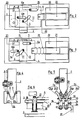
- Figure 1 shows an exploded view of the main parts comprising the frame (1) of the lock, a bolt (2) held between spacers (10, 11, and 12) on which is fixed a fixed plate (3).
- a bolt (2) held between spacers (10, 11, and 12) on which is fixed a fixed plate (3).
- spacers (10, 11, and 12) On a face of the bolt are fixed by a screw (7), two ball bearings (5 and 6) with interposed washers allowing the locking of the two bearings by their internal wheel, the external wheel remaining free to rotate.
- These two bearings will be the articulation around which, thanks to the fixed plate (3) and a movable plate (4), an electromagnet (20) will transmit its movement in a movement perpendicular to its axis.
- the ball bearing (5) will guide the bolt rolling in the oblong slot (13) whose length determines the stroke of the bolt and whose width is 0.2 to 0.3mm greater than the outer diameter of the bearing so that the latter can roll on either of the edges of the slot, without friction of metal parts.
- the ball bearing (6) goes roll in an oblique slot (17) of the movable plate (4). This moves, guided by the two ball bearings (10 a and 11 a) fixedly attached to the fixed plate by the screws of the spacers (10 and 11), the bearings being locked by their internal wheel, the remaining external wheel free to rotate.
- the movable plate (4) has two oblong slots (14 and 15) whose length determines the stroke of this movable plate and whose width exceeds by 0.2mm the outside diameter of the bearings, so that according to the movements and mechanical stresses printed during the raising and lowering of the bolt, the bearings (10 a and 11 a) will roll on one or the other of the edges of the slots (14 and 15) avoiding any friction with the movable plate.
- the oblique slot (17) of the movable plate has a width of 0.2 to 0.3mm greater than the outside diameter of the bearing (6).
- the obliquity of this slot is such that during the movement of the movable plate in one direction or the other, it causes the ascent and descent or rather the re-entry and exit of the bolt (2) out of the lock.
- the bearing (6) rolling on one or other of the edges of the slot.
- the oblique slot (17) has two slopes. One long (17 a), at about 45 degrees angle with the edge (18), the second slope (17 b), short, end of race, made with the same edge an angle of 10 to 15 degrees , angle of the same sign, that is to say that during the movement of the bearing in the slot (17) with double slope, crossing from one slope to another does not change the direction of movement of the bolt which differentiates the present invention from the prior art, in US Patent No. 1,946,384 in which not only is there no use of ball bearings, but also a similar oblique slot presents a change of angle at the end of the stroke but this change of angle causes the direction of travel of the bolt to change and makes this lock completely unbreakable, unlike the lock of the present invention.
- the spacers (10, 11 and 12) each comprise one or two ball bearings (10 b, 10 c, 11 b, 11 c, 12 b, 12 c,) facilitating the movements of the bolt (2), rolling on the outer wheels of these bearings.
- the movable plate (4) is attached to the plunger core (21) of the electromagnet (20).
- the lock is in the locked position.
- the core (21) came to bonding.
- the spring (22) is compressed and the movable plate has been drawn towards the electromagnet, the bearing (6) rolling in the slot (17) has caused the bolt (2) to protrude out of the lock.
- Figure (3) shows the unlocked lock, electromagnet (20) not powered, the spring (22) has pushed back the movable plate assembly (4) - core (21).
- the ball bearing (6) rolled on the corresponding side of the slot (17) and caused the retraction of the bolt (2) (dotted in the figure).
- Figure 4 shows a mode of cooperation of the bolt in the keeper.
- the bolt (2) has its tapered end like a double bevel chisel (8 and 9). It will be introduced into a keeper (24) at the orifice of which there are two small ball bearings (25 and 26) sufficiently spaced so that the bolt does not lock between the two bearings at the end of its stroke. .
- the bolt which begins its projecting movement does not need to be rigorously in front of the keeper. Indeed, one of the bevels comes to roll on one of the corresponding bearings and corrects the position of the door, obviating a possible insufficiency of the door reminder device called "groom".
- Figure 5 shows another mode of latch-strike cooperation.
- the bolt is bevelled and indented and has a ball bearing 31 at its end, blocked by its internal wheel on the bolt, the external wheel free to rotate, cooperating with a keeper made of a set of metal parts fixed by a bracket to the door.
- This mechanical assembly consists of a kind of double-sloping groove that flares at the inlet orifice and tightens in depth.
- Each wall of the groove is a folded or arched plate (24) with a surface slope (24 a) and a deep slope (24 b) longer.
- Each arched or folded part (24), at the end of (24 b), is linked to a rectangular part (34) by a hinge pin (33), the two parts (34) joined by a screw (36) with double reverse thread, allowing the parts (34), and therefore the lower ends of the slopes (24 b) to be moved away and closer.
- the two parts (34) once adjusted to their correct spacing are locked on the bracket (37).
- the two arched parts (24) can deviate from one another rotating around the two axes (33). This spacing can be adjusted by another screw (35) with double reverse thread, allowing the distance and the approximation of the arched parts (24).
- the two planes (24 b) By acting on the screws (35 and 36), it is possible to bring the two planes (24 b) parallel to the axis of the bolt and separated from the value of the diameter of the ball bearing. At this time, the planes (24 a) make a small flare, facilitating the introduction of the bolt into the keeper; the planes (24 b), parallel to each other, provide a strike plate, the walls of which are perpendicular to any driving force. In this condition, the electromagnet (20) being energized, the bolt is out, the lock is unbreakable, and can then be used as a lock for airlocks of banks or entry of buildings.
- a proximity detector (23) is fixed on the fixed plate (3) opposite the end of travel of the movable plate. Coupled with a relay, it has multiple uses: end-of-travel indicator, bringing into play an economy resistor in series with the electromagnet.
- the bolt can remain protruding out of the lock after the electromagnet (20) has been de-energized, thanks to a kind of key or stud (27) (FIG. 1 and 2) which can block the moving plate near the end of its stroke.
- This stud is activated by a second electromagnet (29) of the pushing type, causing it to protrude through a hole in the fixed plate.
- Figure 6 shows a longitudinal section through the stud (27), non-magnetic metal, brass or dural.
- This stud is sheathed in its lower half by a magnetic metal tube (28), realizing with the coil (29) electro-magnet of the pushing type which, supplied, attracts the metal tube (28) therefore makes the stud (27) protrude.
- the coil (29) is fixed on the fixed plate.
- the pin or stud (27), when it projects, moved by the electromagnet (29), is one to two mm away from the edge of the movable plate when the electromagnet (20 ⁇ 21 ) is at collage.
- the spring (22) pushes back the movable plate (4) by one to two mm and this hangs on the stud (27) which itself is blocked by the movable plate.
- the bolt is then blocked projecting from the lock and the lock is closed in the absence of current.
- the proximity detector (23) or a second proximity detector is placed opposite the end of the stud (27) and detects it in the extended position. This signal is brought back to a control panel.
- a timed power supply can be used: first switching on the electromagnets (20 and 29), then switching off the electromagnet (20) two or three seconds before switching off of the electromagnet (29).
- the electromagnet that held it must be de-energized.
- the stud has its free end, without vis-à-vis, which makes it possible to place a proximity detector opposite its end to control it.
- provision must be made for the possibility of a power failure and the possibility of mechanically actuating the lock.
- FIG. 1 shows a key cylinder (39) (40) with a cam cam (38), quarter turn.
- the cam is located in the same plane as the movable plate (4).
- the barrel is fixed on the stationary body of the lock. Performing its quarter turn, the threshing cam pushes the movable plate to its complete end of travel.
- the lock is mechanically locked in this way by a key. Carrying out the reverse quarter turn, the cam disappears and leaves the movable plate (4) pushed back - by the spring (22), the bolt enters, the lock is open. If the lock was blocked by the stud (27), the cam can unlock it, because it can push the moving plate until the complete end of its stroke. For safety reasons, it is advantageous to control the position of the cam, by a micro-contact which sends the information to the control panel.
- the device according to the invention is particularly intended for the electro-mechanical remote-controlled locking of building doors, bank airlock doors, emergency exits from places open to the public and from all doors, in all cases where there must be access control or restriction.
Landscapes
- Physics & Mathematics (AREA)
- Electromagnetism (AREA)
- Lock And Its Accessories (AREA)
- Selective Calling Equipment (AREA)
- Switches That Are Operated By Magnetic Or Electric Fields (AREA)
- Compounds Of Alkaline-Earth Elements, Aluminum Or Rare-Earth Metals (AREA)
- Plural Heterocyclic Compounds (AREA)
- Nitrogen Condensed Heterocyclic Rings (AREA)
Claims (7)
Priority Applications (1)
| Application Number | Priority Date | Filing Date | Title |
|---|---|---|---|
| AT84401132T ATE34423T1 (de) | 1983-06-22 | 1984-06-05 | Fernbedientes elektrisches schloss. |
Applications Claiming Priority (2)
| Application Number | Priority Date | Filing Date | Title |
|---|---|---|---|
| FR8310292A FR2547851B1 (fr) | 1983-06-22 | 1983-06-22 | Serrure electrique telecommandee |
| FR8310292 | 1983-06-22 |
Publications (2)
| Publication Number | Publication Date |
|---|---|
| EP0130101A1 EP0130101A1 (de) | 1985-01-02 |
| EP0130101B1 true EP0130101B1 (de) | 1988-05-18 |
Family
ID=9290040
Family Applications (1)
| Application Number | Title | Priority Date | Filing Date |
|---|---|---|---|
| EP84401132A Expired EP0130101B1 (de) | 1983-06-22 | 1984-06-05 | Fernbedientes elektrisches Schloss |
Country Status (6)
| Country | Link |
|---|---|
| EP (1) | EP0130101B1 (de) |
| AT (1) | ATE34423T1 (de) |
| AU (1) | AU3018084A (de) |
| DE (1) | DE3471335D1 (de) |
| FR (1) | FR2547851B1 (de) |
| WO (1) | WO1985000190A1 (de) |
Families Citing this family (4)
| Publication number | Priority date | Publication date | Assignee | Title |
|---|---|---|---|---|
| EP0190917A3 (de) * | 1985-02-05 | 1988-09-14 | Titon Hardware Limited | Schlossbedienungsmechanismus |
| DE3631043C1 (en) * | 1986-09-12 | 1988-03-17 | Franz Dipl-Ing Schmidt | Door fastening, especially for motor vehicles |
| DE10105445B4 (de) * | 2000-10-13 | 2012-07-26 | Witte-Velbert Gmbh & Co. Kg | Drehfallenverschluss |
| CN202530851U (zh) * | 2012-04-24 | 2012-11-14 | 闵瑜 | 一种锁芯拨块定位装置 |
Family Cites Families (7)
| Publication number | Priority date | Publication date | Assignee | Title |
|---|---|---|---|---|
| US1736761A (en) * | 1929-02-18 | 1929-11-19 | Haffner Charles | Electrical door lock |
| US1946384A (en) * | 1933-02-16 | 1934-02-06 | Lucien R Baril | Electric lock |
| CH206143A (de) * | 1938-10-12 | 1939-07-31 | Jaeger Georg | Schloss. |
| DE2261385C3 (de) * | 1971-12-29 | 1978-09-28 | Jean Dr. Paris Arouete | Elektromagnetische Verriegelungsvorrichtung eines Schlosses |
| US3893723A (en) * | 1974-01-31 | 1975-07-08 | Esdras Boule | Electromagnetic door lock |
| US4021065A (en) * | 1975-07-08 | 1977-05-03 | Geringer Arthur V | Electric lock |
| AU501920B2 (en) * | 1975-11-21 | 1979-07-05 | Access Control Systems Australia Pty. Ltd | Electrically actuated doorlock |
-
1983
- 1983-06-22 FR FR8310292A patent/FR2547851B1/fr not_active Expired
-
1984
- 1984-06-05 WO PCT/FR1984/000144 patent/WO1985000190A1/fr not_active Ceased
- 1984-06-05 AU AU30180/84A patent/AU3018084A/en not_active Abandoned
- 1984-06-05 EP EP84401132A patent/EP0130101B1/de not_active Expired
- 1984-06-05 AT AT84401132T patent/ATE34423T1/de not_active IP Right Cessation
- 1984-06-05 DE DE8484401132T patent/DE3471335D1/de not_active Expired
Also Published As
| Publication number | Publication date |
|---|---|
| FR2547851A1 (fr) | 1984-12-28 |
| DE3471335D1 (en) | 1988-06-23 |
| EP0130101A1 (de) | 1985-01-02 |
| WO1985000190A1 (fr) | 1985-01-17 |
| FR2547851B1 (fr) | 1985-09-13 |
| ATE34423T1 (de) | 1988-06-15 |
| AU3018084A (en) | 1985-01-25 |
Similar Documents
| Publication | Publication Date | Title |
|---|---|---|
| FR2536108A1 (fr) | Serrure de securite pour porte principale d'un local, tel qu'un appartement | |
| EP0292361B1 (de) | Elektrisch betätigbares Schloss | |
| EP0130101A1 (de) | Fernbedientes elektrisches Schloss | |
| EP1030011A1 (de) | Kupplungsvorrichtung für einen Schlossaussengriff und seinen beweglichen Schlossriegel | |
| EP0485248A1 (de) | Kontrolle für einen Panikverschluss | |
| FR2565282A2 (fr) | Serrure electrique telecommandee | |
| CA2061455C (fr) | Embrayage mecanique a validation electrique | |
| FR2695675A1 (fr) | Dispositif par électro-magnétisme linéaire ou rotatif pour mouvoir et retenir une serrure électro-mécanique. | |
| FR2610977A1 (fr) | Serrure de haute-surete actionnee par un moteur | |
| EP2390443B1 (de) | Türpaneel, das mit einem Türschlosssystem ausgestattet ist | |
| EP0360696B1 (de) | Verriegelungsvorrichtung für eine zweiflügelige Tür | |
| EP0182729B1 (de) | Elektrisches Schloss mit einem speziell geformten Schliessstück, insbesondere für Eingangstüren gesicherter Räume | |
| EP3707329B1 (de) | Elektromagnetisch verriegelnde türschliessvorrichtung | |
| EP0213051B1 (de) | Treibstangenschloss mit Einbruchsicherung | |
| EP0029403B1 (de) | Treibstangenschloss für Tür, Fenstertür od. dgl. | |
| BE1026220B1 (fr) | Fenêtre oscillo-battante à ouverture motorisée et manuelle | |
| EP1383980B1 (de) | Autonome motorantriebseinheit für ein schiebetor | |
| FR2682421A1 (fr) | Procede et dispositif de verrouillage de porte sans gache. | |
| FR2653157A1 (fr) | Porte a deplacement lateral a panneaux articules avec manóoeuvre electrique. | |
| FR2621349A1 (fr) | Dispositif electromagnetique de maintien en position fermee d'un panneau ouvrant | |
| CA1279202C (fr) | Serrure electrique a gache de forme particuliere, notamment pour porte d'acces a des locaux securises | |
| EP0389728A2 (de) | Elektromotorisch angetriebenes Sicherheitsschloss mit doppeltem Riegel | |
| WO2003067006A1 (fr) | Dispositif de securite a verrouillage et a condamnation automatiques differees jusqu'a la complete fermeture de la porte | |
| FR2697278A1 (fr) | Dispositif de verrouillage/déverrouillage pour portail à deux battants, et portail équipé d'un tel dispositif. | |
| FR2662734A1 (fr) | Serrure decondamnable a distance. |
Legal Events
| Date | Code | Title | Description |
|---|---|---|---|
| PUAI | Public reference made under article 153(3) epc to a published international application that has entered the european phase |
Free format text: ORIGINAL CODE: 0009012 |
|
| AK | Designated contracting states |
Designated state(s): AT BE CH DE GB IT LI NL |
|
| 17P | Request for examination filed |
Effective date: 19850628 |
|
| 17Q | First examination report despatched |
Effective date: 19860424 |
|
| GRAA | (expected) grant |
Free format text: ORIGINAL CODE: 0009210 |
|
| RAP1 | Party data changed (applicant data changed or rights of an application transferred) |
Owner name: PRETEUX Owner name: AROUETE, JEAN |
|
| AK | Designated contracting states |
Kind code of ref document: B1 Designated state(s): AT BE CH DE GB IT LI NL |
|
| REF | Corresponds to: |
Ref document number: 34423 Country of ref document: AT Date of ref document: 19880615 Kind code of ref document: T |
|
| REF | Corresponds to: |
Ref document number: 3471335 Country of ref document: DE Date of ref document: 19880623 |
|
| GBT | Gb: translation of ep patent filed (gb section 77(6)(a)/1977) | ||
| ITF | It: translation for a ep patent filed | ||
| REG | Reference to a national code |
Ref country code: CH Ref legal event code: PFA Free format text: ENTREPRISE ELECTRICITE PRETEUX |
|
| BECN | Be: change of holder's name |
Effective date: 19880518 |
|
| PG25 | Lapsed in a contracting state [announced via postgrant information from national office to epo] |
Ref country code: NL Effective date: 19890101 |
|
| NLV4 | Nl: lapsed or anulled due to non-payment of the annual fee | ||
| RAP2 | Party data changed (patent owner data changed or rights of a patent transferred) |
Owner name: ENTREPRISE ELECTRICITE PRETEUX Owner name: AROUETE, JEAN |
|
| PLBE | No opposition filed within time limit |
Free format text: ORIGINAL CODE: 0009261 |
|
| STAA | Information on the status of an ep patent application or granted ep patent |
Free format text: STATUS: NO OPPOSITION FILED WITHIN TIME LIMIT |
|
| 26N | No opposition filed | ||
| PG25 | Lapsed in a contracting state [announced via postgrant information from national office to epo] |
Ref country code: AT Effective date: 19890605 |
|
| PG25 | Lapsed in a contracting state [announced via postgrant information from national office to epo] |
Ref country code: LI Effective date: 19890630 Ref country code: CH Effective date: 19890630 Ref country code: BE Effective date: 19890630 |
|
| BERE | Be: lapsed |
Owner name: ENTREPRISE ELECTRICITE PRETEUX Effective date: 19890630 Owner name: AROUETE JEAN Effective date: 19890630 |
|
| REG | Reference to a national code |
Ref country code: CH Ref legal event code: PL |
|
| ITTA | It: last paid annual fee | ||
| PGFP | Annual fee paid to national office [announced via postgrant information from national office to epo] |
Ref country code: GB Payment date: 19950515 Year of fee payment: 12 |
|
| PGFP | Annual fee paid to national office [announced via postgrant information from national office to epo] |
Ref country code: DE Payment date: 19950518 Year of fee payment: 12 |
|
| PG25 | Lapsed in a contracting state [announced via postgrant information from national office to epo] |
Ref country code: GB Effective date: 19960605 |
|
| GBPC | Gb: european patent ceased through non-payment of renewal fee |
Effective date: 19960605 |
|
| PG25 | Lapsed in a contracting state [announced via postgrant information from national office to epo] |
Ref country code: DE Effective date: 19970301 |