EP0130235B1 - Gerät zum Erzeugen eines Hochdruckwasserstrahls - Google Patents
Gerät zum Erzeugen eines Hochdruckwasserstrahls Download PDFInfo
- Publication number
- EP0130235B1 EP0130235B1 EP83110228A EP83110228A EP0130235B1 EP 0130235 B1 EP0130235 B1 EP 0130235B1 EP 83110228 A EP83110228 A EP 83110228A EP 83110228 A EP83110228 A EP 83110228A EP 0130235 B1 EP0130235 B1 EP 0130235B1
- Authority
- EP
- European Patent Office
- Prior art keywords
- nozzle
- ultrahigh pressure
- water
- pump
- pressure water
- Prior art date
- Legal status (The legal status is an assumption and is not a legal conclusion. Google has not performed a legal analysis and makes no representation as to the accuracy of the status listed.)
- Expired - Lifetime
Links
Images





Classifications
-
- B—PERFORMING OPERATIONS; TRANSPORTING
- B08—CLEANING
- B08B—CLEANING IN GENERAL; PREVENTION OF FOULING IN GENERAL
- B08B3/00—Cleaning by methods involving the use or presence of liquid or steam
- B08B3/02—Cleaning by the force of jets or sprays
- B08B3/026—Cleaning by making use of hand-held spray guns; Fluid preparations therefor
- B08B3/028—Spray guns
-
- B—PERFORMING OPERATIONS; TRANSPORTING
- B05—SPRAYING OR ATOMISING IN GENERAL; APPLYING FLUENT MATERIALS TO SURFACES, IN GENERAL
- B05B—SPRAYING APPARATUS; ATOMISING APPARATUS; NOZZLES
- B05B3/00—Spraying or sprinkling apparatus with moving outlet elements or moving deflecting elements
- B05B3/02—Spraying or sprinkling apparatus with moving outlet elements or moving deflecting elements with rotating elements
-
- B—PERFORMING OPERATIONS; TRANSPORTING
- B05—SPRAYING OR ATOMISING IN GENERAL; APPLYING FLUENT MATERIALS TO SURFACES, IN GENERAL
- B05B—SPRAYING APPARATUS; ATOMISING APPARATUS; NOZZLES
- B05B9/00—Spraying apparatus for discharge of liquids or other fluent material, without essentially mixing with gas or vapour
- B05B9/03—Spraying apparatus for discharge of liquids or other fluent material, without essentially mixing with gas or vapour characterised by means for supplying liquid or other fluent material
- B05B9/04—Spraying apparatus for discharge of liquids or other fluent material, without essentially mixing with gas or vapour characterised by means for supplying liquid or other fluent material with pressurised or compressible container; with pump
- B05B9/0403—Spraying apparatus for discharge of liquids or other fluent material, without essentially mixing with gas or vapour characterised by means for supplying liquid or other fluent material with pressurised or compressible container; with pump with pumps for liquids or other fluent material
- B05B9/0413—Spraying apparatus for discharge of liquids or other fluent material, without essentially mixing with gas or vapour characterised by means for supplying liquid or other fluent material with pressurised or compressible container; with pump with pumps for liquids or other fluent material with reciprocating pumps, e.g. membrane pump, piston pump, bellow pump
-
- B—PERFORMING OPERATIONS; TRANSPORTING
- B08—CLEANING
- B08B—CLEANING IN GENERAL; PREVENTION OF FOULING IN GENERAL
- B08B3/00—Cleaning by methods involving the use or presence of liquid or steam
- B08B3/02—Cleaning by the force of jets or sprays
- B08B3/026—Cleaning by making use of hand-held spray guns; Fluid preparations therefor
-
- F—MECHANICAL ENGINEERING; LIGHTING; HEATING; WEAPONS; BLASTING
- F04—POSITIVE - DISPLACEMENT MACHINES FOR LIQUIDS; PUMPS FOR LIQUIDS OR ELASTIC FLUIDS
- F04B—POSITIVE-DISPLACEMENT MACHINES FOR LIQUIDS; PUMPS
- F04B1/00—Multi-cylinder machines or pumps characterised by number or arrangement of cylinders
- F04B1/04—Multi-cylinder machines or pumps characterised by number or arrangement of cylinders having cylinders in star- or fan-arrangement
- F04B1/053—Multi-cylinder machines or pumps characterised by number or arrangement of cylinders having cylinders in star- or fan-arrangement with actuating or actuated elements at the inner ends of the cylinders
-
- F—MECHANICAL ENGINEERING; LIGHTING; HEATING; WEAPONS; BLASTING
- F04—POSITIVE - DISPLACEMENT MACHINES FOR LIQUIDS; PUMPS FOR LIQUIDS OR ELASTIC FLUIDS
- F04B—POSITIVE-DISPLACEMENT MACHINES FOR LIQUIDS; PUMPS
- F04B53/00—Component parts, details or accessories not provided for in, or of interest apart from, groups F04B1/00 - F04B23/00 or F04B39/00 - F04B47/00
- F04B53/10—Valves; Arrangement of valves
- F04B53/12—Valves; Arrangement of valves arranged in or on pistons
- F04B53/125—Reciprocating valves
- F04B53/129—Poppet valves
-
- B—PERFORMING OPERATIONS; TRANSPORTING
- B08—CLEANING
- B08B—CLEANING IN GENERAL; PREVENTION OF FOULING IN GENERAL
- B08B2203/00—Details of cleaning machines or methods involving the use or presence of liquid or steam
- B08B2203/02—Details of machines or methods for cleaning by the force of jets or sprays
- B08B2203/0205—Bypass pressure relief valves
-
- B—PERFORMING OPERATIONS; TRANSPORTING
- B08—CLEANING
- B08B—CLEANING IN GENERAL; PREVENTION OF FOULING IN GENERAL
- B08B2203/00—Details of cleaning machines or methods involving the use or presence of liquid or steam
- B08B2203/02—Details of machines or methods for cleaning by the force of jets or sprays
- B08B2203/0229—Suction chambers for aspirating the sprayed liquid
Definitions
- This invention relates to an ultrahigh pressure water apparatus in accordance with the pre-characterizing part of claim 1, e.g. used to clean the surface of the object, peeling a coating off the surface, or removing rust from the surface.
- the conventional ultrahigh pressure water apparatus has been designed so that a plurality of jets of water at ultrahigh pressure of 2,000 kg/cm 2 , may be projected thorugh a nozzle gun thereof and, by suitable movement of the nozzle gun enables to dash against a given object uniformly throughout the entire surface thereof. For the entire surface of the object to be uniformly cleaned or stripped of the coating, therefore, the nozzle gun has been required to be moved delicately. Since the delicacy with which the movement of the nozzle gun is controlled has its own limit, it has been inevitable that the individual jets of water projected through the nozzle gun should be given a large diameter.
- GB-A-2096021 discloses an ultrahigh pressure water apparatus the nozzle gun of which outputs a jet having a small diameter at an ultrahigh pressure.
- a mechanical oscillator which oscillates the front end of the high pressure hose such that the jet goes up and down with respect to a surface to be treated. While the apparatus is concurrently moved into a direction perpendicular with respect to the oscillating movement, a zig-zag path is obtained and, thereby, there is treated a relatively great area.
- the nozzle is held at a certain distance from the surface to be treated.
- the problems underlying the present invention is to provide an ultrahigh pressure water apparatus such that the nozzle gun thereof will be easily operated in hands with high efficiency and without any danger.
- This problem is solved in accordance with claim 1 by providing a multiple nozzle head which is rotated during operation, wherein a collector cover is used to support the nozzle gun with respect to a surface to be treated and, moreover, to collect spent water without jeopardizing the environment during the operation of the apparatus.
- the jet of water dashes against a given surface not at one fixed point but along a circle. Even when the beam of water has a small diameter, the nozzle is capable of dashing the jet of water uniformly against the surface of the object.
- a pump to be used in connection with the present apparatus is described in the co-pending EP-application No. 88115148.4.
- a collector is disposed to enclose the nozzle cover.
- the collector has its opening in the direction in which the nozzle projects the jet or water.
- the portion of the of water rebounded by the surface of the object enters the interior of the collector.
- a suction hose communicates with the interior of the collector. Through this suction hose, the interior of the collector is kept evacuated with a vacuum pump.
- the rebounded water which has entered the interior of the collector therefore, is withdrawn through the suction hose. The possibility of the environment of the operation of the generator being defiled by the rebounded water is eliminated.
- Fig. 1 illustrates, in outline, a piping system to be laid out in a typical ultrahigh pressure water apparatus according to the present invention.
- the water introduced through a water inlet pipe 11 has its pressure increased by a backup pump 12 and then is forwarded to a filter 13.
- the water is freed of foreign particles by the filter 13 and then forwarded to a manifold pipe 14.
- the water is divided into four streams through feed water pipes 15a-15d and forwarded to an ultrahigh pressure pump 16.
- This ultrahigh pressure pump 16 is a plunger type four-pole pump. Into four pump sections 17a-17d of this pump 16, the streams of water through the feed water pipes 15a-15d are supplied.
- the streams of water which have their pressure increased to ultrahigh pressure inside the pump are sent through discharge pipes 18a-18d to a pressure regulating valve, i.e. a relief valve 19.
- the streams of water have their ultrahigh pressure adjusted by the relief valve 19 to a desired level. They are forwarded through a pipe 21 to an accumulator 22.
- the accumulator 22 converts the streams of water sequentially and repeatedly brought in through the four pump sections 17a-17d into a substantially continuous stream of ultrahigh pressure water and forwards this continuous stream of water to a high pressure hose 23, which communicates with a nozzle gun 24. Through this nozzle gun 24, the ultrahigh pressure water is projected in the form of a jet of ultrahigh pressure water.
- the lubricating oil inside an oil tank 25 has its pressure increased by a pressurizing pump 26 and is forwarded to a manifold 27.
- the manifold 27 supplies the lubricating oil through oil feed pipes 28a-28d respectively to the pump sections 17a-17d.
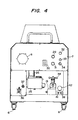
- Fig. 2 through Fig. 4 illustrate typical layouts of the parts of the ultrahigh pressure water apparatus according to the present invention, with the covers removed to show the interiors thereof to better advantage.
- the pipes distributed to the relevant parts are omitted from the diagrams.
- Casters 6 are attached to the underside of a base plate 5 to facilitate the transportation of the apparatus.
- a panel 7 covers the upper half of the front side of the apparatus.
- a pressure gauge 8 indicating the pressure of the jet of water projected through the nozzle is fixed in one half portion.
- the relief valve 19 is provided with a pressure regulating handle 38. By suitable control of the pressure regulating handle 38, the aperture of the valve is adjusted and the pressure of the projected water is fixed.
- a water feed inlet pipe 39 communicating with the water inlet pipe 11 and a water drain outlet 41 serving to drain the part of water spent in the relief valve 19.
- the pressure of the water received in the water feed inlet 39 is measured by a feed water pressure gauge 42.
- the ultrahigh pressure pump 16 and a motor 43 for driving the pump are sequentially disposed on the base plate 5 behind the panel 7.
- the motor 43 may be an induction motor 3-phase 50 Hz rated for 1,440 rpm, for example.
- the motor 43 is provided on the rotary shaft thereof with a toothed wheel 44 and the ultrahigh pressure pump 16 is provided on the drive shaft thereof with a toothed wheel 45.
- a chain is passed around these toothed wheels 44,45, so that the rotation of the motor 43 may be transmitted to the pump 16.
- the backup pump 12 is disposed on the water feed inlet 39 side of the ultrahigh pressure pump 16 and the accumulator 22 is disposed on the high pressure outlet 36 side of the ultrahigh pressure pump 16 respectively.
- the filter 13 is disposed beside the motor 43.
- a terminal box 47 for the motor 43 is attached to the top of the motor 43.
- a typical nozzle gun 24 will be described with reference to Figs. 5 and 6.
- a shaft tube 92 is rotatably supported via a bearing 93.
- a metal pipe 90 is rotatably inserted into the shaft tube 92.
- One end of the metal pipe 90 is connected to the high pressure hose 23.
- a nozzle retainer 94 is fastened to the protruding portion of the other end of the metal pipe 90.
- a plurality of retaining holes 95 are formed in the end surface of the nozzle retainer 94. Nozzles 96 are embedded one each in these retaining holes 95 and setscrews 97 are driven in to immobilize the nozzles 96 to the nozzle retainer 94.
- a filter holder 99 communicating with the nozzle retainer 94 is formed on the high pressure hose 23 side of the nozzle retainer 94 and a filter 101 for stopping foreign particles is accommodated inside the filter holder 99.
- a high pressure water manifold 102 communicating with the filter holder 99 is formed in the nozzle retainer 94. The high pressure manifold 102 communicates with the nozzle retaining holes 95. Consequently, the ultrahigh pressure water inside the high pressure hose 23 is passed through the filter 101 and the manifold 102 and projected through the nozzles 96.
- Each nozzle 96 is composed, as illustrated in Fig. 7 and Fig. 8, of a pair of retaining pieces 103, 104 made of a metallic material such as Monel Metal and a nozzle body 105 made of diamond sandwiched by the retaining pieces 103, 104.
- recesses 106, 107 are formed in an opposing relationship and they permit the nozzle body 105 fitted and retained therein.
- the retaining pieces 103,104 kept in their mutually adjoining state are fused together.
- a nozzle orifice 108 is formed in the nozzle body 105. The diameter of this nozzle orifice 108 determines the diameter of the jet of ultrahigh pressure water projected through the orifice.
- the diameter of the nozzle orifice 108 is fixed at 0.18 mm, for example.
- An angular hole is formed in the setscrew 97. By inserting a fastening device inside this angular hole, the setscrew 97 can be easily fastened inside the retaining hole 95. By this fastening, the 0-ring 98 is pressed against the bottom of the retaining hole 95 so as to prevent otherwise possible leakage of ultrahigh pressure water.
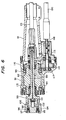
- the center 111 of the inner wall of the shaft tube 92 is deviated by d 2 (5 mm, for example), relative to the center 109 of the peripheral surface of the shaft tube 92 (see Fig. 9).
- a bearing is interposed between the shaft tube 92 and the metal pipe 90.
- a drive shaft 113 is disposed substantially in parallel to the high pressure hose 23 (under the nozzle cover 91 as illustrated in the diagram). By the rotation of this drive shaft 113, the shaft tube 92 is rotated.
- a toothed wheel 114 is fixed on the drive shaft 113 and part of this toothed wheel 114 is allowed to take its position inside the nozzle cover 91 through an opening 115 formed in the nozzle cover 91.
- a toothed wheel 116 is fixed on the peripheral surface of the shaft tube 92. These toothed wheels 114, 116 are meshed with each other. Part of the nozzle cover is extended to conceal the toothed wheel 114.
- the drive shaft 113 is pivotally supported by the bearing 117 inside the extended part of the cover 91.
- the drive shaft 113 is connected to a flexible shaft 118 which is threaded through a flexible sheath 120.
- the free end of the flexible shaft 118 is connected to the rotary shaft of a motor 123 for the motion of the nozzle disposed close to the main body of the apparatus on which the ultrahigh pressure pump 16 and the motor 43 are disposed.
- a support pipe 119 is connected to the end of the nozzle cover 91 falling on the opposite side of the nozzle retainer 94.
- the high pressure pipe 23 is inserted into the support pipe 119.
- the flexible shaft 118 is laid along the support pipe 119.
- a pair of retainers 121, 122 are fastened to the support pipe 119 and the flexible sheath 120.
- a power source cord 124 is led into the retainer 122.
- Inside the retainer 122 there is disposed an ON-OFF control switch 125 for a power source line wrapped in the power source cord 124.
- the power source cord 124 is laid along the flexible sheath 120.
- the power for driving the motor 123 is derived from the power source connector 36 already described with reference to Fig. 4.
- the motor 123 for the operation of the nozzle can be set rotating or stopped.
- the flexible shaft 118 is rotated and, as the result, the drive shaft 113 is rotated.
- the rotation is transmitted via the toothed wheels 114, 116 to the shaft tube 92. Since the center of the inner wall of the shaft tube 92 is deviated relative to the center 109 of the peripheral surface thereof, the high pressure pipe 23 is caused to rotate about the center 109 of the peripheral surface of the shaft tube 92. Consequently, the jet of water projected through the nozzle 96 is rotated in conjunction with the rotation of the high pressure pipe 23.
- the ultrahigh pressure of water can be dashed uniformly within a fixed range of area against the object.
- the diameter of the jet of water may be decreased. This means that the amount of water projected per unit time can be decreased and the nozzle can be light enough to be manually handled easily without any danger. It can be used to spurt the ultrahigh pressure water at portions of complicated objects which can not easily be treated with the conventional ultrahigh pressure water apparatus.
- the ultrahigh pressure water apparatus may be designed so as to collect the portion of water rebounded from the object.
- a collector 126 is disposed to enclose the nozzle retainer 94 at the end part of the nozzle cover 91.
- the collector 126 has its opening in the direction in which the jet of water is projected through the nozzle retainer 94.
- a circular plate 126a of the collector 126 centering around the nozzle cover 91 is fastened to the nozzle cover 91 and a tubular part 126b is integrally extended from the peripheral edge of the circular plate 126a in parallel to the nozzle retainer 94.
- an elastic pad 127 made of rubber is thrust out in the direction of the object 128.
- Three casters 129 are fixed on the periphery at the end part of the tubular part 126b.
- the casters 129 are rolled on the object 128 to freely move the nozzle retainer 94 along the surface of the object 128 while keeping the distance L between the nozzle retainer 94 and the surface of the object 128 constant.
- To the tubular part 126b of the collector 126 is connected a drain hose 131 communicating with the interior of the collector 126.
- the drain hose 131 is connected, as illustrated in Fig. 11, to the interior of a tank 132.
- the air inside the tank 132 is withdrawn by a vacuum pump 133.
- the water which is projected in the form of jets of ultrahigh pressure water may contain therein such chemicals as detergent and rustproofing agent in advance. Not only fresh water but also sea water may be used for the cleaning work by the use of the apparatus of this invention.
- the drive source for the operation of the ultrahigh pressure pump 16 need not be limited to a motor. An engine may be adopted instead.
Landscapes
- Engineering & Computer Science (AREA)
- Mechanical Engineering (AREA)
- General Engineering & Computer Science (AREA)
- Cleaning By Liquid Or Steam (AREA)
Claims (4)
Applications Claiming Priority (4)
| Application Number | Priority Date | Filing Date | Title |
|---|---|---|---|
| JP103124/83U | 1983-07-01 | ||
| JP10312483U JPS6013274U (ja) | 1983-07-01 | 1983-07-01 | 回収機能を持つノズル |
| JP123085/83U | 1983-08-08 | ||
| JP12308583U JPS6030378U (ja) | 1983-08-08 | 1983-08-08 | 超高圧水ポンプ |
Related Child Applications (3)
| Application Number | Title | Priority Date | Filing Date |
|---|---|---|---|
| EP88115148A Division-Into EP0304964B1 (de) | 1983-07-01 | 1983-10-13 | Vorrichtung, um einen Wasserstrahl unter Ultrahochdruck zu erzeugen |
| EP88115148A Division EP0304964B1 (de) | 1983-07-01 | 1983-10-13 | Vorrichtung, um einen Wasserstrahl unter Ultrahochdruck zu erzeugen |
| EP88115148.4 Division-Into | 1983-10-13 |
Publications (3)
| Publication Number | Publication Date |
|---|---|
| EP0130235A2 EP0130235A2 (de) | 1985-01-09 |
| EP0130235A3 EP0130235A3 (en) | 1987-07-01 |
| EP0130235B1 true EP0130235B1 (de) | 1990-04-04 |
Family
ID=26443776
Family Applications (2)
| Application Number | Title | Priority Date | Filing Date |
|---|---|---|---|
| EP88115148A Expired EP0304964B1 (de) | 1983-07-01 | 1983-10-13 | Vorrichtung, um einen Wasserstrahl unter Ultrahochdruck zu erzeugen |
| EP83110228A Expired - Lifetime EP0130235B1 (de) | 1983-07-01 | 1983-10-13 | Gerät zum Erzeugen eines Hochdruckwasserstrahls |
Family Applications Before (1)
| Application Number | Title | Priority Date | Filing Date |
|---|---|---|---|
| EP88115148A Expired EP0304964B1 (de) | 1983-07-01 | 1983-10-13 | Vorrichtung, um einen Wasserstrahl unter Ultrahochdruck zu erzeugen |
Country Status (3)
| Country | Link |
|---|---|
| US (2) | US4534711A (de) |
| EP (2) | EP0304964B1 (de) |
| DE (2) | DE3382372D1 (de) |
Families Citing this family (38)
| Publication number | Priority date | Publication date | Assignee | Title |
|---|---|---|---|---|
| DE3424862C1 (de) * | 1984-07-06 | 1985-07-25 | Hauhinco Maschinenfabrik G. Hausherr, Jochums Gmbh & Co Kg, 4300 Essen | Radialkolbenpumpe fuer hydraulische Medien |
| JPS61230900A (ja) * | 1985-04-03 | 1986-10-15 | 日東紡績株式会社 | 高圧流体加工装置 |
| JPS6238257A (ja) * | 1985-08-09 | 1987-02-19 | R D Kosan Kk | 超高圧水噴射装置 |
| US4795217A (en) * | 1986-03-07 | 1989-01-03 | Hydro-Ergon Corporation | System for removing material with a high velocity jet of working fluid |
| US4761039A (en) * | 1986-03-07 | 1988-08-02 | Hydro-Ergon Corporation | Cutting head for removing material with a high velocity jet of working liquid |
| JPH0811203B2 (ja) * | 1986-05-13 | 1996-02-07 | 株式会社スギノマシン | 超高圧液体噴射装置 |
| US4715539A (en) * | 1986-12-11 | 1987-12-29 | Steele Curtis C | High-pressure water jet tool and seal |
| US4957131A (en) * | 1987-12-23 | 1990-09-18 | Robinson James L | Animal waste flushing assembly |
| GB2221630B (en) * | 1988-08-11 | 1992-02-12 | Paul Hammelmann | Nozzle head |
| US5037276A (en) * | 1989-04-04 | 1991-08-06 | Flow International Corporation | High pressure pump valve assembly |
| US5078161A (en) * | 1989-05-31 | 1992-01-07 | Flow International Corporation | Airport runway cleaning method |
| DE3934740A1 (de) * | 1989-10-18 | 1991-04-25 | Fath Bruno | Vorrichtung fuer die spruehdesinfektion von zahnaerztlichen handinstrumenten an behandlungseinheiten |
| DE9005313U1 (de) * | 1990-05-10 | 1991-03-28 | Kopania, Karlheinz, 4650 Gelsenkirchen | Hochdruckwasserstrahlgerät |
| DE4221086C2 (de) * | 1991-11-06 | 2000-02-10 | Dieter Albrecht | Vorrichtung zum Beseitigen von Material unterhalb des Spiegels eines Mediums |
| US5558562A (en) * | 1991-12-11 | 1996-09-24 | Diat; Christian | Method for micro-cleaning a support and apparatus for implementing same |
| FR2684900B1 (fr) * | 1991-12-11 | 1995-03-17 | Christian Diat | Buse rotative multi-jets pour la projection de particules abrasives tres fines. |
| CA2090371A1 (en) * | 1992-03-27 | 1993-09-28 | William Frank Banholzer | Water jet mixing tubes used in water jet cutting devices and method of preparation thereof |
| US5360165A (en) * | 1992-09-28 | 1994-11-01 | Singhal Tara C | Spray paint nozzle and nozzle shroud |
| JP2759861B2 (ja) * | 1992-10-02 | 1998-05-28 | 日清紡績株式会社 | 液圧ポンプ |
| US5756155A (en) * | 1996-01-22 | 1998-05-26 | Taiwan Semiconductor Manufacturing Company, Ltd. | Combination nozzle and vacuum hood that is self cleaning |
| DE19609896C2 (de) * | 1996-03-13 | 1998-04-30 | Wagner Gmbh J | Farbspritzgerät |
| DE19711837A1 (de) * | 1997-03-21 | 1998-09-24 | Hammelmann Paul Maschf | Düsenkopf mit einem um eine Längsachse drehbar gelagerten, antreibbaren Düsenträger |
| NL1006384C2 (nl) * | 1997-06-24 | 1998-12-28 | Gerardus Hendrikus Wegkamp | Ergonomische hogedrukspuitkap met volledig zicht op de waterstraal. |
| US6077362A (en) * | 1998-06-11 | 2000-06-20 | Reed; William Mark | Portable feces dispersal device |
| US6425805B1 (en) | 1999-05-21 | 2002-07-30 | Kennametal Pc Inc. | Superhard material article of manufacture |
| DE60036356T2 (de) * | 1999-12-10 | 2008-05-29 | Sankyo Aqua System Co., Ltd. | Düse sowie zugehöriger Absauger |
| US6629649B2 (en) * | 2000-05-05 | 2003-10-07 | Sealant Equipment & Engineering, Inc. | Orbital applicator tool with static mixer tip seal valve |
| US6675548B2 (en) * | 2000-08-31 | 2004-01-13 | Dyk Incorporated | Method and apparatus for texturizing tank walls |
| US20080053495A1 (en) * | 2006-09-06 | 2008-03-06 | Emp Advanced Development, Llc | Fluid cleaning system |
| JP4365853B2 (ja) * | 2006-12-04 | 2009-11-18 | 株式会社丸山製作所 | 往復動ポンプ |
| US20090223014A1 (en) * | 2008-03-10 | 2009-09-10 | Tyler R. Clemons | Gum removal tool |
| TWI531446B (zh) * | 2008-08-07 | 2016-05-01 | 不二製作所股份有限公司 | 噴砂方法及具有研磨料回收系統的設備、薄膜太陽能電池板的加工處理方法及以此方法加工處理的薄膜太陽能電池板 |
| TW201022346A (en) * | 2008-12-04 | 2010-06-16 | pin-cong Zheng | Rubber particle composition and production method thereof |
| WO2010122851A1 (ja) * | 2009-04-21 | 2010-10-28 | シャープ株式会社 | ブラスト装置およびブラスト加工方法 |
| NO329833B1 (no) * | 2009-05-13 | 2011-01-03 | Olav Haughom As | Anordning ved pumpestempel |
| US10017006B1 (en) | 2017-06-02 | 2018-07-10 | Control Devices, Llc | Roller kit for power washer surface cleaner attachment and corresponding method |
| GB2571465B (en) * | 2019-05-15 | 2020-03-18 | Md Engineering Solutions Ltd | A receptacle washing device |
| WO2021182502A1 (ja) * | 2020-03-13 | 2021-09-16 | 日本製紙株式会社 | 染料分散剤 |
Citations (4)
| Publication number | Priority date | Publication date | Assignee | Title |
|---|---|---|---|---|
| US2544976A (en) * | 1946-06-21 | 1951-03-13 | Bendix Aviat Corp | Pump |
| US3019739A (en) * | 1959-03-23 | 1962-02-06 | Union Carbide Corp | High pressure pumping apparatus |
| GB1409461A (en) * | 1973-04-06 | 1975-10-08 | Union Carbide Corp | Close clearance viscous fluid seal system |
| DE2424046A1 (de) * | 1974-05-17 | 1975-11-27 | Hauhinco Maschf | Hochdruckwasserpumpe |
Family Cites Families (16)
| Publication number | Priority date | Publication date | Assignee | Title |
|---|---|---|---|---|
| GB385887A (en) * | 1932-07-14 | 1933-01-05 | Maurice Michael Eaton | Improvements relating to pumps |
| GB635718A (en) * | 1947-05-12 | 1950-04-12 | Mactaggart Scott & Company Ltd | Improvements in and relating to reciprocating pumps |
| US2754847A (en) * | 1951-07-20 | 1956-07-17 | Electrol Inc | Piston-type accumulators |
| FR1300822A (fr) * | 1961-06-23 | 1962-08-10 | Sames Mach Electrostat | Perfectionnements aux têtes de pulvérisation de liquides pour le revêtement d'objets |
| US3270674A (en) * | 1963-05-31 | 1966-09-06 | Georgia Tech Res Inst | Variable displacement pump |
| US3288072A (en) * | 1965-01-13 | 1966-11-29 | Walker Mfg Co | Pump |
| GB1255090A (en) * | 1969-03-26 | 1971-11-24 | Nippon Kogei Kogyo Company Ltd | Apparatus for electrostatically coating powders on a workpiece |
| US3653598A (en) * | 1970-05-28 | 1972-04-04 | Amchem Prod | Vibrating spray apparatus and method of spraying |
| GB1302163A (de) * | 1970-10-24 | 1973-01-04 | ||
| US4045915A (en) * | 1975-10-06 | 1977-09-06 | Enviro-Blast International | Portable sandblaster |
| SU584898A1 (ru) * | 1976-08-17 | 1977-12-25 | Предприятие П/Я А-1698 | Устройство дл нанесени покрытий |
| DE7813438U1 (de) * | 1978-05-03 | 1978-09-14 | Kraenzle, Josef, 7918 Illertissen | Mehrfachduesenkopf |
| JPS5645334A (en) * | 1979-09-22 | 1981-04-25 | Tsukahara Koichi | Processing device with extra-high pressure water |
| US4369850B2 (en) * | 1980-07-28 | 1989-06-06 | High pressure fluid jet cutting and drilling apparatus | |
| US4341350A (en) * | 1980-09-05 | 1982-07-27 | Otto Wemmer | Chemical injection system for high pressure washers |
| GB2096021B (en) * | 1981-03-24 | 1985-01-23 | British Hydromechanics | High pressure liquid jetting guns |
-
1983
- 1983-10-13 EP EP88115148A patent/EP0304964B1/de not_active Expired
- 1983-10-13 DE DE8888115148T patent/DE3382372D1/de not_active Expired - Lifetime
- 1983-10-13 DE DE8383110228T patent/DE3381401D1/de not_active Expired - Lifetime
- 1983-10-13 EP EP83110228A patent/EP0130235B1/de not_active Expired - Lifetime
- 1983-10-17 US US06/542,810 patent/US4534711A/en not_active Expired - Fee Related
-
1985
- 1985-02-13 US US06/701,331 patent/US4600149A/en not_active Expired - Fee Related
Patent Citations (4)
| Publication number | Priority date | Publication date | Assignee | Title |
|---|---|---|---|---|
| US2544976A (en) * | 1946-06-21 | 1951-03-13 | Bendix Aviat Corp | Pump |
| US3019739A (en) * | 1959-03-23 | 1962-02-06 | Union Carbide Corp | High pressure pumping apparatus |
| GB1409461A (en) * | 1973-04-06 | 1975-10-08 | Union Carbide Corp | Close clearance viscous fluid seal system |
| DE2424046A1 (de) * | 1974-05-17 | 1975-11-27 | Hauhinco Maschf | Hochdruckwasserpumpe |
Also Published As
| Publication number | Publication date |
|---|---|
| EP0130235A2 (de) | 1985-01-09 |
| US4534711A (en) | 1985-08-13 |
| EP0130235A3 (en) | 1987-07-01 |
| DE3382372D1 (de) | 1991-09-12 |
| EP0304964A2 (de) | 1989-03-01 |
| EP0304964A3 (en) | 1989-05-17 |
| US4600149A (en) | 1986-07-15 |
| EP0304964B1 (de) | 1991-08-07 |
| DE3381401D1 (de) | 1990-05-10 |
Similar Documents
| Publication | Publication Date | Title |
|---|---|---|
| EP0130235B1 (de) | Gerät zum Erzeugen eines Hochdruckwasserstrahls | |
| US3645452A (en) | Tank cleaner | |
| US3599871A (en) | Jet spray tank cleaner | |
| US20200130023A1 (en) | Vacuum spray apparatus and uses thereof | |
| US4339840A (en) | Rotary flooring surface treating device | |
| US5970574A (en) | Apparatus and method for cleaning surfaces by removing and containing waste | |
| US7736526B2 (en) | Method of filtering phosphate utilizing a rotary table filter or horizontal table filter | |
| US20250091067A1 (en) | Nozzle handle apparatus with built-in air regulation | |
| EP0769351A1 (de) | Bodenflächenstrahlgerät | |
| JPS6271586A (ja) | パイプのクリ−ニング装置 | |
| JP2020143527A (ja) | アスベスト除去装置、アスベスト除去システム及びアスベスト除去方法 | |
| JP2719107B2 (ja) | 高圧水噴射装置 | |
| US11407251B2 (en) | Paint roller cover cleaner | |
| KR101857849B1 (ko) | 회전식 날 연마장치 | |
| CN114734359A (zh) | 一种角度可调节全方位打磨铝型材表面抛光机构 | |
| US20050183745A1 (en) | Tank cleaning device | |
| WO1996000138A1 (en) | Shot blast delivery and recovery unit | |
| JPH06320426A (ja) | 流体ジェット噴流式切断装置用の液体・研磨材粒子供給装置 | |
| GB2318280A (en) | Paint roller cleaning apparatus | |
| WO1997035672A1 (en) | Equipment for cleaning spray guns | |
| JPS628263B2 (de) | ||
| JP2001179143A (ja) | 回転ノズルを備える装置 | |
| JP3201879U (ja) | 路面用噴水型除去装置 | |
| US4292770A (en) | Yarn heater track cleaning apparatus and method | |
| JPS632657A (ja) | レ−ザプロ−ブの研磨装置 |
Legal Events
| Date | Code | Title | Description |
|---|---|---|---|
| PUAI | Public reference made under article 153(3) epc to a published international application that has entered the european phase |
Free format text: ORIGINAL CODE: 0009012 |
|
| 17P | Request for examination filed |
Effective date: 19831028 |
|
| AK | Designated contracting states |
Designated state(s): CH DE FR GB IT LI NL SE |
|
| PUAL | Search report despatched |
Free format text: ORIGINAL CODE: 0009013 |
|
| AK | Designated contracting states |
Kind code of ref document: A3 Designated state(s): CH DE FR GB IT LI NL SE |
|
| 17Q | First examination report despatched |
Effective date: 19880429 |
|
| GRAA | (expected) grant |
Free format text: ORIGINAL CODE: 0009210 |
|
| AK | Designated contracting states |
Kind code of ref document: B1 Designated state(s): DE FR GB |
|
| REF | Corresponds to: |
Ref document number: 3381401 Country of ref document: DE Date of ref document: 19900510 |
|
| ET | Fr: translation filed | ||
| PLBE | No opposition filed within time limit |
Free format text: ORIGINAL CODE: 0009261 |
|
| STAA | Information on the status of an ep patent application or granted ep patent |
Free format text: STATUS: NO OPPOSITION FILED WITHIN TIME LIMIT |
|
| 26N | No opposition filed | ||
| REG | Reference to a national code |
Ref country code: FR Ref legal event code: TP |
|
| REG | Reference to a national code |
Ref country code: GB Ref legal event code: 732 |
|
| PGFP | Annual fee paid to national office [announced via postgrant information from national office to epo] |
Ref country code: FR Payment date: 19920831 Year of fee payment: 10 |
|
| PGFP | Annual fee paid to national office [announced via postgrant information from national office to epo] |
Ref country code: GB Payment date: 19921002 Year of fee payment: 10 |
|
| PGFP | Annual fee paid to national office [announced via postgrant information from national office to epo] |
Ref country code: DE Payment date: 19921029 Year of fee payment: 10 |
|
| PG25 | Lapsed in a contracting state [announced via postgrant information from national office to epo] |
Ref country code: GB Effective date: 19931013 |
|
| GBPC | Gb: european patent ceased through non-payment of renewal fee |
Effective date: 19931013 |
|
| PG25 | Lapsed in a contracting state [announced via postgrant information from national office to epo] |
Ref country code: FR Effective date: 19940630 |
|
| PG25 | Lapsed in a contracting state [announced via postgrant information from national office to epo] |
Ref country code: DE Effective date: 19940701 |
|
| REG | Reference to a national code |
Ref country code: FR Ref legal event code: ST |