EP0130285A1 - Convertisseur - Google Patents
Convertisseur Download PDFInfo
- Publication number
- EP0130285A1 EP0130285A1 EP84103676A EP84103676A EP0130285A1 EP 0130285 A1 EP0130285 A1 EP 0130285A1 EP 84103676 A EP84103676 A EP 84103676A EP 84103676 A EP84103676 A EP 84103676A EP 0130285 A1 EP0130285 A1 EP 0130285A1
- Authority
- EP
- European Patent Office
- Prior art keywords
- line
- current
- positive
- negative
- thyristor
- Prior art date
- Legal status (The legal status is an assumption and is not a legal conclusion. Google has not performed a legal analysis and makes no representation as to the accuracy of the status listed.)
- Granted
Links
- 238000010791 quenching Methods 0.000 claims description 19
- 230000000171 quenching effect Effects 0.000 claims description 17
- 239000003990 capacitor Substances 0.000 claims description 4
- 238000004804 winding Methods 0.000 description 9
- 230000008901 benefit Effects 0.000 description 5
- 238000004519 manufacturing process Methods 0.000 description 2
- 238000005259 measurement Methods 0.000 description 2
- XEEYBQQBJWHFJM-UHFFFAOYSA-N Iron Chemical group [Fe] XEEYBQQBJWHFJM-UHFFFAOYSA-N 0.000 description 1
- 230000009471 action Effects 0.000 description 1
- 230000008859 change Effects 0.000 description 1
- 238000011161 development Methods 0.000 description 1
- 230000018109 developmental process Effects 0.000 description 1
- 238000009826 distribution Methods 0.000 description 1
- 230000000694 effects Effects 0.000 description 1
- 230000004907 flux Effects 0.000 description 1
- 238000009499 grossing Methods 0.000 description 1
- 238000000034 method Methods 0.000 description 1
- 238000012216 screening Methods 0.000 description 1
- 230000001629 suppression Effects 0.000 description 1
- 238000012546 transfer Methods 0.000 description 1
Images


Classifications
-
- H—ELECTRICITY
- H02—GENERATION; CONVERSION OR DISTRIBUTION OF ELECTRIC POWER
- H02M—APPARATUS FOR CONVERSION BETWEEN AC AND AC, BETWEEN AC AND DC, OR BETWEEN DC AND DC, AND FOR USE WITH MAINS OR SIMILAR POWER SUPPLY SYSTEMS; CONVERSION OF DC OR AC INPUT POWER INTO SURGE OUTPUT POWER; CONTROL OR REGULATION THEREOF
- H02M7/00—Conversion of AC power input into DC power output; Conversion of DC power input into AC power output
- H02M7/42—Conversion of DC power input into AC power output without possibility of reversal
- H02M7/44—Conversion of DC power input into AC power output without possibility of reversal by static converters
- H02M7/48—Conversion of DC power input into AC power output without possibility of reversal by static converters using discharge tubes with control electrode or semiconductor devices with control electrode
- H02M7/505—Conversion of DC power input into AC power output without possibility of reversal by static converters using discharge tubes with control electrode or semiconductor devices with control electrode using devices of a thyratron or thyristor type requiring extinguishing means
- H02M7/515—Conversion of DC power input into AC power output without possibility of reversal by static converters using discharge tubes with control electrode or semiconductor devices with control electrode using devices of a thyratron or thyristor type requiring extinguishing means using semiconductor devices only
- H02M7/521—Conversion of DC power input into AC power output without possibility of reversal by static converters using discharge tubes with control electrode or semiconductor devices with control electrode using devices of a thyratron or thyristor type requiring extinguishing means using semiconductor devices only in a bridge configuration
-
- H—ELECTRICITY
- H02—GENERATION; CONVERSION OR DISTRIBUTION OF ELECTRIC POWER
- H02M—APPARATUS FOR CONVERSION BETWEEN AC AND AC, BETWEEN AC AND DC, OR BETWEEN DC AND DC, AND FOR USE WITH MAINS OR SIMILAR POWER SUPPLY SYSTEMS; CONVERSION OF DC OR AC INPUT POWER INTO SURGE OUTPUT POWER; CONTROL OR REGULATION THEREOF
- H02M7/00—Conversion of AC power input into DC power output; Conversion of DC power input into AC power output
- H02M7/66—Conversion of AC power input into DC power output; Conversion of DC power input into AC power output with possibility of reversal
- H02M7/68—Conversion of AC power input into DC power output; Conversion of DC power input into AC power output with possibility of reversal by static converters
- H02M7/72—Conversion of AC power input into DC power output; Conversion of DC power input into AC power output with possibility of reversal by static converters using discharge tubes with control electrode or semiconductor devices with control electrode
- H02M7/75—Conversion of AC power input into DC power output; Conversion of DC power input into AC power output with possibility of reversal by static converters using discharge tubes with control electrode or semiconductor devices with control electrode using devices of a thyratron or thyristor type requiring extinguishing means
- H02M7/757—Conversion of AC power input into DC power output; Conversion of DC power input into AC power output with possibility of reversal by static converters using discharge tubes with control electrode or semiconductor devices with control electrode using devices of a thyratron or thyristor type requiring extinguishing means using semiconductor devices only
Definitions
- the invention relates to a thyristor inverter according to the preamble of the main claim.
- Thyristor inverters are already known in many forms.
- DE-OS 22 39 396 describes a thyristor inverter with forced commutation, which is supplied by a DC voltage source and generates a three-phase current for operating an asynchronous motor.
- chokes are connected in the individual bridge branches of the inverter, which are used to screen out harmonics from the supply voltage of the three-phase asynchronous machine.
- This circuit arrangement has the disadvantage that a choke is necessary for each branch of the asynchronous machine. If the inverter is to be as efficient as possible, it is necessary to divide these chokes and place them on a common iron core.
- the thyristor inverter according to the invention with the characterizing features of the main claim has the advantage that the required choke is easy to manufacture and also the same main inductance in series with the machine terminals is effective in every switching state of the inverter. This makes it possible to keep the frequency of the intermediate clocking of the inverter to a minimum and prevents the energy stored in the choke from being uselessly pulsed back and forth between the choke and the DC voltage source or being converted into heat in short-circuit circuits.
- the inverter according to the invention therefore has a high efficiency and is also inexpensive to manufacture.
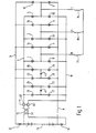
- FIGS. 1 and 2 show three-phase inverters for operating a three-phase machine with windings 17, 18 and 19 from a direct voltage which is obtained, for example, from a rectifier or from a battery 29.
- the positive battery voltage reaches a group of main valves 1, 3 and 5, which are connected to the positive supply voltage line 7, via a choke 51 and an ammeter 61. Thyristors are particularly suitable as valves.
- the The negative battery terminal is connected to the negative supply voltage line 8, which is connected to the main valves 2, 4 and 6.
- Return valves 11 to 16 are assigned to each of the valves 1 to 6, which serve at the same time for the distribution of the extinguishing energy.
- the return delivery valves 11, 13 and 15 are connected to the negative return delivery line 10, which in turn leads to an ammeter 62.
- the current meter 62 is followed by a choke 52 which is magnetically closely coupled to the choke 51 and preferably has the same number of turns.
- the inductor 52 is followed by a diode 31 which is switched in the reverse direction and leads to the negative supply voltage line 8.
- the return delivery valves 12, 14 and 16 are connected to the positive return delivery line 9, which is connected via a diode 32 to the positive battery terminal.
- Each valve group 1, 3 and 5 or 2, 4, 6 is assigned an extinguishing device via the return valves 11, 13, 15 or 12, 14 and 16.
- the quenching device with the bridge circuit of the thyristors 21, 23, 25 and 27 and the capacitor 41 serves to quench the first valve group
- the quenching device with the thyristors 22, 24, 26 and 28 and with the capacitor 42 serves to quench the second group of thyristors
- the first quenching bridge is connected between the positive supply voltage line 7 and the negative return current line 10
- the second quenching bridge is arranged between the negative supply voltage line 8 and the positive return current line 9.
- Terminals R, S and T are connected to the middle of the bridges with the main valves and the return valves, to which a three-phase machine with the windings 17, 18 and 19 is connected in a star connection.
- the embodiment of Figure 2 differs from the embodiment of Figure 1 in that the chokes 51 and 52 with the downstream current measuring devices 61 and 62 are not connected directly to the battery, but are arranged between the quenching bridges and the bridges with the main valves. Your mode of action is not affected.
- a current flows through the diode 31, the inductor 52 and the current transformer 62 to the switched thyristor 11. From here the current reaches the winding 17 and the winding 19 via the terminal R and leaves the asynchronous machine via the terminal T. The current in turn reaches the diode 31 via the thyristor 2.
- the same main inductance is effective in the machine circuit, since current is always flowing through one of the two chokes 51 or 52.
- the same inductance is therefore always effective for smoothing the current ripple, regardless of the operating state of the inverter.
- the inductance of the coupled chokes can be of any size. This does not delay the current transfer from one machine terminal to the other. Because the same choke inductance is always effective in the machine circuit, control methods of the inverter are possible in which the frequency of intermediate clocking is limited to a minimum. This also prevents the energy stored in the chokes 51 and 52 from being uselessly pulsed back and forth between the choke and the DC voltage source or being converted into heat in short-circuit circuits.
- This arrangement of the chokes also avoids additional voltage on the valves during current commutation, since the magnetic flux through the main inductor does not change suddenly changes, but the current only passes from one winding 51 to the other 52 ′. All in all, this results in a high arrangement efficiency and good utilization of the inverter and machine in every operating area.
- the arrangement of the current transformers directly behind the chokes ensures that the number of current transformers is limited to two and that the terminal current can be measured without gaps and without interferences. Since the current flows through the chokes only in one direction, the arrangement of the current transformers directly behind the chokes has the further advantage that only a single current direction can be measured.
- the electrical circuit of the current measuring device is significantly simplified.
- FIG. 2 The circuit arrangement shown in FIG. 2 is functionally identical to the circuit arrangement shown in FIG. 1, so that a detailed description is unnecessary.
- the effect and function of the quenching bridges have already been described in detail in the publications mentioned above, so that they are no longer explained here.
- the arrangement according to the invention with the coupled chokes and the downstream current transformers is not limited to thyristor inverters with group suppression.
- Figure 3 shows the general arrangement when the main valves are individually deleted, for. B. thyristors with individual extinguishing devices or erasable thyristors or transistors are provided via the gate. The quenching bridges and the return diodes are then no longer required.
- the main ones Block valves in the reverse direction and the return valves must be controllable, otherwise the function of the throttle and the summation current transformer according to the invention is not available in every switching state, in particular not in the freewheeling switching state.
- FIG. 3 is otherwise wired the same except for the aforementioned missing elements.
- the choke 51 the output of which leads to a current transformer 61, is connected to the positive pole of the battery 29.
- the main valves 2, 4 and 6 lead from the middle of the bridge to the negative supply voltage line 8, which is connected to the negative pole of the battery 29.
- the return flow valves 11, 13 and 15 lead to the negative return flow line 10 from the respective bridge center, while the return flow valves 12, 14 and 16 are connected to the positive return flow line 9.
- the positive return current line 9 is connected to the positive terminal 29, the negative return current line 10 is connected to the negative terminal of the battery 29 via the current transformer 62 and the inductor 52.
Landscapes
- Engineering & Computer Science (AREA)
- Power Engineering (AREA)
- Inverter Devices (AREA)
- Power Conversion In General (AREA)
Applications Claiming Priority (2)
| Application Number | Priority Date | Filing Date | Title |
|---|---|---|---|
| DE19833316806 DE3316806A1 (de) | 1983-05-07 | 1983-05-07 | Thyristor-wechselrichter |
| DE3316806 | 1983-05-07 |
Publications (2)
| Publication Number | Publication Date |
|---|---|
| EP0130285A1 true EP0130285A1 (fr) | 1985-01-09 |
| EP0130285B1 EP0130285B1 (fr) | 1987-01-21 |
Family
ID=6198468
Family Applications (1)
| Application Number | Title | Priority Date | Filing Date |
|---|---|---|---|
| EP84103676A Expired EP0130285B1 (fr) | 1983-05-07 | 1984-04-04 | Convertisseur |
Country Status (2)
| Country | Link |
|---|---|
| EP (1) | EP0130285B1 (fr) |
| DE (2) | DE3316806A1 (fr) |
Citations (3)
| Publication number | Priority date | Publication date | Assignee | Title |
|---|---|---|---|---|
| US3733539A (en) * | 1971-03-24 | 1973-05-15 | Bosch Gmbh Robert | Multi-phase thyristor inverter |
| US3825813A (en) * | 1972-08-10 | 1974-07-23 | Bosch Gmbh Robert | Multi-phase thyristor inverter circuit |
| DE3027280A1 (de) * | 1980-07-18 | 1982-02-11 | Vsr Martin Eng Gmbh | Thyristorgesteuerter loeschkreis fuer wechselrichter |
-
1983
- 1983-05-07 DE DE19833316806 patent/DE3316806A1/de not_active Withdrawn
-
1984
- 1984-04-04 EP EP84103676A patent/EP0130285B1/fr not_active Expired
- 1984-04-04 DE DE8484103676T patent/DE3462205D1/de not_active Expired
Patent Citations (4)
| Publication number | Priority date | Publication date | Assignee | Title |
|---|---|---|---|---|
| US3733539A (en) * | 1971-03-24 | 1973-05-15 | Bosch Gmbh Robert | Multi-phase thyristor inverter |
| US3825813A (en) * | 1972-08-10 | 1974-07-23 | Bosch Gmbh Robert | Multi-phase thyristor inverter circuit |
| GB1446002A (en) * | 1972-08-10 | 1976-08-11 | Bosch Gmbh Robert | Converters |
| DE3027280A1 (de) * | 1980-07-18 | 1982-02-11 | Vsr Martin Eng Gmbh | Thyristorgesteuerter loeschkreis fuer wechselrichter |
Also Published As
| Publication number | Publication date |
|---|---|
| EP0130285B1 (fr) | 1987-01-21 |
| DE3462205D1 (en) | 1987-02-26 |
| DE3316806A1 (de) | 1984-11-08 |
Similar Documents
| Publication | Publication Date | Title |
|---|---|---|
| DE3854586T2 (de) | Leistungswandlungseinrichtung. | |
| DE102017108142A1 (de) | Vorrichtung und verfahren zur steuerung von elektrischen antrieben mit rekonfigurierbarer wicklung | |
| DE102017108331A1 (de) | Verfahren zur umschaltung zwischen einem vollwicklungsmodus und einem halbwicklungsmodus in einer drehstrommaschine | |
| DE3490475T1 (de) | Stromquellen-Sinusstromrichter | |
| EP3383692A1 (fr) | Convertisseur statique | |
| DE9216662U1 (de) | Vorladeschaltung mit kombiniertem Überspannungsschutz für einen netzgeführten Stromrichter mit ausgangsseitigem Kondensator | |
| EP0597409B1 (fr) | Véhicule multisystème | |
| EP3167298B1 (fr) | Procédé de contrôle d'un élément semi-conducteur haute puissance | |
| DE19607201A1 (de) | Störschutzfilter für Spannungsquellen-Wechselrichter | |
| EP0130285B1 (fr) | Convertisseur | |
| DE2248938A1 (de) | Gleichrichter-schaltungsanordnung | |
| DE2739387A1 (de) | Schaltregler, insbesondere doppelpulsiger schaltregler | |
| DE102015105889A1 (de) | Schaltmodul und Umrichter mit wenigstens einem Schaltmodul | |
| DE19648948C1 (de) | Wechselrichter mit Bremssteller | |
| DE4042378C2 (fr) | ||
| DE2552410C3 (de) | Umrichterschaltung | |
| DE3831126A1 (de) | Schaltungsanordnung und steuerverfahren fuer einen wechselrichter mit eingepraegter zwischenkreisspannung | |
| DE2002943A1 (de) | Kurzschlussschutzeinrichtung | |
| DE4018165C1 (en) | High power insulated gate transistor circuitry - has additional capacitor and thyristor fired by rectifier overcurrent in series across DC voltage source | |
| DE2158531C2 (de) | Kommutierungsschaltung für einen Wechselrichter | |
| AT288551B (de) | Schaltanordnung zur umschaltung der anzapfungen eines stelltransformators | |
| DE221661C (fr) | ||
| AT378290B (de) | Elektronischer schalter | |
| DE1513023C (fr) | ||
| DE427486C (de) | Schaltung fuer zwei oder mehrere Motoren, die in Reihe, parallel oder in Reihe und parallel geschaltet werden koennen, mit Drosselspulen, die mehrere sich gegenseitig induzierende Wicklungen aufweisen, insbesondere fuer Bahnbetrieb |
Legal Events
| Date | Code | Title | Description |
|---|---|---|---|
| PUAI | Public reference made under article 153(3) epc to a published international application that has entered the european phase |
Free format text: ORIGINAL CODE: 0009012 |
|
| 17P | Request for examination filed |
Effective date: 19840404 |
|
| AK | Designated contracting states |
Designated state(s): DE FR GB |
|
| 17Q | First examination report despatched |
Effective date: 19860320 |
|
| GRAA | (expected) grant |
Free format text: ORIGINAL CODE: 0009210 |
|
| AK | Designated contracting states |
Kind code of ref document: B1 Designated state(s): DE FR GB |
|
| REF | Corresponds to: |
Ref document number: 3462205 Country of ref document: DE Date of ref document: 19870226 |
|
| ET | Fr: translation filed | ||
| PLBE | No opposition filed within time limit |
Free format text: ORIGINAL CODE: 0009261 |
|
| STAA | Information on the status of an ep patent application or granted ep patent |
Free format text: STATUS: NO OPPOSITION FILED WITHIN TIME LIMIT |
|
| 26N | No opposition filed | ||
| PG25 | Lapsed in a contracting state [announced via postgrant information from national office to epo] |
Ref country code: GB Effective date: 19881123 |
|
| GBPC | Gb: european patent ceased through non-payment of renewal fee | ||
| PG25 | Lapsed in a contracting state [announced via postgrant information from national office to epo] |
Ref country code: FR Free format text: LAPSE BECAUSE OF NON-PAYMENT OF DUE FEES Effective date: 19881229 |
|
| REG | Reference to a national code |
Ref country code: FR Ref legal event code: ST |
|
| PGFP | Annual fee paid to national office [announced via postgrant information from national office to epo] |
Ref country code: DE Payment date: 19900626 Year of fee payment: 7 |
|
| PG25 | Lapsed in a contracting state [announced via postgrant information from national office to epo] |
Ref country code: DE Effective date: 19920201 |