EP0130492A2 - Flüssigkristallanzeige - Google Patents
Flüssigkristallanzeige Download PDFInfo
- Publication number
- EP0130492A2 EP0130492A2 EP84107145A EP84107145A EP0130492A2 EP 0130492 A2 EP0130492 A2 EP 0130492A2 EP 84107145 A EP84107145 A EP 84107145A EP 84107145 A EP84107145 A EP 84107145A EP 0130492 A2 EP0130492 A2 EP 0130492A2
- Authority
- EP
- European Patent Office
- Prior art keywords
- liquid crystal
- orientation
- crystal display
- display
- cell
- Prior art date
- Legal status (The legal status is an assumption and is not a legal conclusion. Google has not performed a legal analysis and makes no representation as to the accuracy of the status listed.)
- Ceased
Links
Images
Classifications
-
- G—PHYSICS
- G02—OPTICS
- G02F—OPTICAL DEVICES OR ARRANGEMENTS FOR THE CONTROL OF LIGHT BY MODIFICATION OF THE OPTICAL PROPERTIES OF THE MEDIA OF THE ELEMENTS INVOLVED THEREIN; NON-LINEAR OPTICS; FREQUENCY-CHANGING OF LIGHT; OPTICAL LOGIC ELEMENTS; OPTICAL ANALOGUE/DIGITAL CONVERTERS
- G02F1/00—Devices or arrangements for the control of the intensity, colour, phase, polarisation or direction of light arriving from an independent light source, e.g. switching, gating or modulating; Non-linear optics
- G02F1/01—Devices or arrangements for the control of the intensity, colour, phase, polarisation or direction of light arriving from an independent light source, e.g. switching, gating or modulating; Non-linear optics for the control of the intensity, phase, polarisation or colour
- G02F1/13—Devices or arrangements for the control of the intensity, colour, phase, polarisation or direction of light arriving from an independent light source, e.g. switching, gating or modulating; Non-linear optics for the control of the intensity, phase, polarisation or colour based on liquid crystals, e.g. single liquid crystal display cells
- G02F1/137—Devices or arrangements for the control of the intensity, colour, phase, polarisation or direction of light arriving from an independent light source, e.g. switching, gating or modulating; Non-linear optics for the control of the intensity, phase, polarisation or colour based on liquid crystals, e.g. single liquid crystal display cells characterised by the electro-optical or magneto-optical effect, e.g. field-induced phase transition, orientation effect, guest-host interaction or dynamic scattering
- G02F1/13725—Devices or arrangements for the control of the intensity, colour, phase, polarisation or direction of light arriving from an independent light source, e.g. switching, gating or modulating; Non-linear optics for the control of the intensity, phase, polarisation or colour based on liquid crystals, e.g. single liquid crystal display cells characterised by the electro-optical or magneto-optical effect, e.g. field-induced phase transition, orientation effect, guest-host interaction or dynamic scattering based on guest-host interaction
-
- G—PHYSICS
- G02—OPTICS
- G02F—OPTICAL DEVICES OR ARRANGEMENTS FOR THE CONTROL OF LIGHT BY MODIFICATION OF THE OPTICAL PROPERTIES OF THE MEDIA OF THE ELEMENTS INVOLVED THEREIN; NON-LINEAR OPTICS; FREQUENCY-CHANGING OF LIGHT; OPTICAL LOGIC ELEMENTS; OPTICAL ANALOGUE/DIGITAL CONVERTERS
- G02F1/00—Devices or arrangements for the control of the intensity, colour, phase, polarisation or direction of light arriving from an independent light source, e.g. switching, gating or modulating; Non-linear optics
- G02F1/01—Devices or arrangements for the control of the intensity, colour, phase, polarisation or direction of light arriving from an independent light source, e.g. switching, gating or modulating; Non-linear optics for the control of the intensity, phase, polarisation or colour
- G02F1/13—Devices or arrangements for the control of the intensity, colour, phase, polarisation or direction of light arriving from an independent light source, e.g. switching, gating or modulating; Non-linear optics for the control of the intensity, phase, polarisation or colour based on liquid crystals, e.g. single liquid crystal display cells
- G02F1/133—Constructional arrangements; Operation of liquid crystal cells; Circuit arrangements
- G02F1/1333—Constructional arrangements; Manufacturing methods
- G02F1/1335—Structural association of cells with optical devices, e.g. polarisers or reflectors
- G02F1/133528—Polarisers
Definitions
- the invention relates to a liquid crystal display according to the preamble of patent claim 1.
- Such a liquid crystal display is known, for example, from DE-B-31 38 518.
- the display described there is based on the rotary cell principle and consists of parallel support plates which form a cell with a frame.
- a nematic liquid crystal with positive dielectric anisotropy is filled into the cell.
- Orientation layers are provided over the electrode layers applied to the inside of the carrier plates, which align the adjacent liquid crystal molecules uniformly with a small angle of attack.
- the preferred directions of the orientation layers form an angle of approximately 70 ° to one another.
- a front polarizer is provided on the front plate, the polarization axis of which runs parallel to the preferred direction of the adjacent orientation layer.
- a back polarizer is provided on the back plate, the polarization axis of which runs perpendicular to the preferred direction of the adjacent orientation layer.
- the plate spacing between the carrier plates is 10 ⁇ m and the refractive index anisotropy of the liquid crystal is about 0.13.
- the brightness of the display is lower compared to a conventional rotary cell display with the same contrast ratio. It can be seen from FIG. 3 of this document that, despite everything, the display has a slight color, which increases as the layer thickness of the liquid crystal decreases.
- the present invention is based on the object of improving the aforementioned liquid crystal display in such a way that it exhibits a lower color and an increased contrast without the brightness decreasing significantly.
- the invention is based on the finding that a largely color-neutral display is achieved by a greater extinguishing capacity of the polarizers in combination with a reduction in the angle between the orinting directions and addition of a small proportion of dye, in particular with a spectral color complementary to the display color.
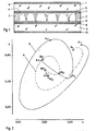
- the display cell consists of two carrier plates 1, 2 made of glass and a border 3 which, as usual, is formed by glass fibers encased in the hardened epoxy adhesive.
- a nematic liquid crystal 4 with positive dielectric anisotropy is filled into the cell, in particular the liquid crystal mixture ZLI 1694 from Merck, Darmstadt (FRG). Two percent by weight of a dichroic dye are added to this liquid crystal.
- Electrode layers 5 and 6, which in this case consist of strips, are applied to the carrier plates 1 and 2, so that a dot matrix display is formed. It goes without saying that other shapes of the electrode layers 5 and 6 can also be selected, such as those that occur in a seven-segment display, for example.
- Orientation layers 7 and 8 made of silane are applied over the electrode layers 5 and 6, the orientation directions of which include an angle ⁇ less than or equal to 80 °.
- the polarization direction of the front polarizer 9 runs parallel to the orientation direction of the orientation layer 7, that of the rear polarizer 10 perpendicular to the orientation direction of the orientation layer 8.
- the polarizers-n have an extinguishing capacity of 100, which is defined as the ratio between the transmission with parallel polarizers and the transmission with crossed polarizers.
- the fourth display cell which meets the conditions according to the invention, has a considerably improved contrast ratio than the other three display cells I to III without the brightness having decreased significantly compared to III.
- the condition according to the invention for the product of layer thickness and refractive index anisotropy d ⁇ ⁇ n can be derived directly from FIG. 2.
- colors can be characterized by two coordinates x and y in the CIE color diagram (1964). Details can be found in the book "Color in Business and Industry” by Judd and Wyszecki.
- Fig. 2 shows the relationship between d ⁇ ⁇ n and the color of the display in the CIE color diagram.
- Curve A relates to a cell with a twist of the liquid crystal of 90 °
- curve B relates to a cell with a twist of 45 °.
- the product d ⁇ ⁇ n passes through the values 0.28 ⁇ m (A 1 , B1), 0.76 ⁇ m (A 2 , B 2 ), 098 ⁇ m (A 3 , B 3 ) and 1.26 pm (A 4 , B 4 ).
- the cell with a twist of 45 ° (curve B) is less colored than the cell with a twist of 90 ° (curve A).
- the angle ⁇ enclosed by the orientation directions is preferably between 60 ° and 40 °. It should be noted that a smaller twist angle reduces the degree of multiplexing (see table).
- an additional dye of up to 3 percent by weight is added, which has the complement of the spectral color of the display.
- the color point of the dye (point 8 4 'in Fig. 2) is determined by the connecting line between the color point of the display (point B 4 ) and the achromatic point D 65, the distances from the points B 4 and B 4 ' to this point are the same.
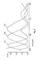
- FIG. 3 shows the transmission curves for three different spectral colors with the product d ⁇ ⁇ n as a variable.
- the transmission coefficient T (in -%) 0 indicated the non-controlled display cell (dark).
- the transmission coefficient in the activated state (bright) is about 25%.
- the first curve C 1 is recorded when illuminated with blue light (450 nm), the second curve C 2 with green light (550 nm) and the third curve C 3 with red light (650 nm). It can be seen from this figure that the display absorbs a specific spectral color more poorly for a specific product d ⁇ ⁇ n.
- the contrast ratio is thereby increased.
- the display appears more clearly, even if the brightness is approximately constant in the activated state.
Landscapes
- Physics & Mathematics (AREA)
- Nonlinear Science (AREA)
- Chemical & Material Sciences (AREA)
- Crystallography & Structural Chemistry (AREA)
- General Physics & Mathematics (AREA)
- Optics & Photonics (AREA)
- Liquid Crystal (AREA)
- Mathematical Physics (AREA)
Abstract
Description
- Die Erfindung betrifft eine Flüssigkristallanzeige nach dem Oberbegriff des Patentanspruchs 1.
- Eine solche Flüssigkristallanzeige ist z.B. bekannt aus DE-B-31 38 518. Die dort beschriebene Anzeige basiert auf dem Drehzellenprinzip und besteht aus parallelen Trägerplatten, die mit einem Rahmen eine Zelle bildet. In die Zelle ist ein nematischer Flüssigkristall mit positiver dielektrischer Anisotropie eingefüllt. Ueber die auf den Innenseiten der Trägerplatten aufgetragenen Elektrodenschichten sind Orientierungsschichten vorgesehen, die die angrenzenden Flüssigkristallmoleküle einheitlich mit einem geringen Anstellwinkel ausrichten. Die Vorzugsrichtungen der Orientierungsschichten bilden einen Winkel von etwa 70° zueinander. Auf der Frontplatte ist ein Frontpolarisator vorgesehen, dessen Polarisationsachse parallel zur Vorzugsrichtung der angrenzenden Orientierungsschicht verläuft. Auf der Rückplatte ist ein Rückpolarisator vorgesehen, dessen Polarisationsachse senkrecht zur Vorzugsrichtung der angrenzenden Orientierungsschicht verläuft. Der Plattenabstand zwischen den Trägerplatten beträgt 10 um und die Brechungsindexanisotropie des Flüssigkristalls ist etwa 0,13.
- Die Helligkeit der Anzeige ist im Vergleich zu einer üblichen Drehzellenanzeige bei gleichem Kontrastverhältnis geringer. Aus der Figur 3 dieser Schrift ist entnehmbar, dass die Anzeige trotz allem eine leichte Farbigkeit aufweist, die mit abnehmender Schichtdicke des Flüssigkristalls grösser wird.
- Der vorliegenden Erfindung, wie sie in den Patentansprüchen gekennzeichnet ist, liegt die Aufgabe zugrunde, die vorgenannte Flüssigkristallanzeige derart zu verbessern, dass sie eine geringere Farbigkeit und einen erhöhten Kontrast vorweist ohne dass die Helligkeit stark abnimmt.
- Die Erfindung beruht auf der Erkenntnis, dass durch ein grösseres Löschvermögen der Polarisatoren in Kombination mit einer Verringerung des Winkels zwischen den Oreintierungsrichtungen und Zufügen eines geringen Anteils an Farbstoff, insbesondere mit einer zur Anzeigefarbe komplementären Spektralfarbe, eine weitgehend farbneutrale Anzeige erreicht wird.
- Zu den wichtigsten Vorteilen der Erfindung gehört der verbesserte Kontrast bei etwa gleichbleibender Helligkeit, so dass eine solche Anzeige besonders geeignet ist für die steten Anzeigen in einem Auto, die unter wechselhaften Lichtbedingungen einwandfrei ablesbar sein sollen. Weitere Vorteile der Erfindung folgen aus einem in den Zeichnungen näher erläuterten Beispiel.
- Dabei zeigt:
- Fig. 1 eine erfindungsgemässe Flüssigkristallanzeige im Querschnitt,
- Fig. 2 Graphen im Farbdiagramm zweier verschiedener Anzeigen mit d · Δ n als Parameter und
- Fig. 3 Transmissionkurven für verschiedene Spektralfarben bei einer erfindungsgemässen Anzeige.
- In Fig. 1 ist eine erfindungsgemässe Flüssigkristallanzeige dargestellt. Die Anzeigezelle besteht aus zwei Trägerplatten 1, 2 aus Glas und aus einer Umrandung 3, die wie üblich von im ausgehärteten Epoxy-Klebstoff gehüllten Glasfasern gebildet wird. In die Zelle ist ein nematischer Flüssigkristall 4 mit positiver dielektrischer Anisotropie eingefüllt, insbesondere die Flüssigkristallmischung ZLI 1694 von der Firma Merck, Darmstadt (BRD). Zu diesem Flüssigkristall sind 2 Gewichtsprozente eines dichroitischen Farbstoffes beigemischt. Auf den Trägerplatten 1 und 2 sind Elektrodenschichten 5 und 6 aufgetragen, die in diesem Fall aus Streifen bestehen, so dass eine Punktmatrixanzeige gebildet wird. Es versteht sich, dass auch andere Formen der Elektrodenschichten 5 und 6 gewählt werden können, wie sie z.B. bei einer Siebensegment-Anzeige vorkommen. Ueber die Elektrodenschichten 5 und 6 sind Orientierungsschichten 7 und 8 aus Silan aufgebracht, deren Orientierungsrichtungen einen Winkel α kleiner oder gleich 80° einschliessen. Auf die Aussenseiten der Trägerplatten 1 und 2 sind ein Frontpolarisator 9 und ein Rückpolarisator 10 aufgeklebt, die aus Polaroid-Folien Q 12-35 der Firma Nitto, Japan, bestehen. Die Polarisationsrichtung des Frontpolarisators 9 verläuft parallel zur Orientierungsrichtung der Orientierungsschicht 7, die des Rückpolarisators 10 senkrecht zur Orientierungsrichtung der Orientierungsschicht 8. Die Polarisationsrichtungen der Polarisatoren bilden daher einen Kinkel /3 = 90° -α, der grösser oder gleich 10° ist. Die Polarisatore-n besitzen ein Löschvermögen von 100, das definiert ist als das Verhältnis zwischen der Transmission bei parallelen Polarisatoren und der Transmission bei gekreuzten Polarisatoren.
- Dadurch wird schon ein erheblich verbessertes Kontrastverhältnis erreicht im Vergleich zu den üblichen Drehzellen.
- Aus der nachstehenden Tabelle sind die Unterschiede in den Betriebsdaten vier verschiedener Anzeigezellen zu entnehmen. In die vier Zellen I-IV ist die Flüssigkristallmischung ZLI 1694 eingefüllt, wobei in die Zelle IV zusätzlich noch 2 Gewichtsprozente eines dichroitischen Farbstoffes beigemischt sind. Die einzelnen Parameter in der Tabelle haben die folgende Bedeutung:
- α der Winkel zwischen den Orientierungsrichtungen der Orientierungsschichten (Verdrillungswinkel des Flüssigkristalls),
- d die Dicke der Flüssigkristallschicht,
- T0 die Transmission der Anzeigezelle im nicht-angesteuerten Zustand,
- Tv die Transmission der Anzeigezelle im angesteuerten Zustand, das Löschvermögen oder Kontrastverhältnis der Anzeigezelle, das gleich dem Verhältnis Tv/To ist,
- U10, 40 die Betriebsspannung bei einer Temperatur von 293 K, einer Transmission von 10 % und einem Sichtwinkel von 40° mit der Normale,
- U50, 0 die Betriebsspannung bei einer Temperatur von 293 K, einer Transmission von 50 % und einem Sichtwinkel von 0° mit der Normale,
- M das Verhältnis U50, 0/U10, 40, das ein Mass ist für die Multiplexierbarkeit (vgl. IEEE Trans. on El. Dev. Vol. ED-21, No. 2 (Febr. 1974), Seiten 146-155).
-

- Wie unmittelbar aus der obigen Tabelle ersichtlich ist, besitzt die vierte Anzeigezelle, die den erfindungsgemässen Bedingungen genügt, ein erheblich verbessertes Kontrastverhältnis als die anderen drei Anzeigezellen I bis III ohne dass die Helligkeit gegenüber III stark abgenommen hat.
- Die erfindungsgemässe Bedingung für das Produkt aus Schichtdicke und Brechungsindexanisotropie d ·Δ n kann man direkt von der Figur 2 ableiten. Bekanntlich können Farben durch zwei Koordinaten x und y im CIE-Farbdiagramm (1964) charakterisiert werden. Einzelheiten dazu sind aus dem Buch "Color in Business and Industry" von Judd und Wyszecki entnehmbar. Der sogenannte Unbuntpunkt für mittleres Tageslicht, in Figur 2 mit D 65 angedeutet, besitzt dabei die Koordinaten x = 0,313 und y = 0,329. Je weiter ein Punkt in diesem Diagramm von dem Punkt D 65 entfernt ist, desto grösser ist die zugehörige Farbigkeit. Fig. 2 zeigt nun den Zusammenhang zwischen d · Δ n und Farbe der Anzeige im CIE-Farbdiagramm. Die Kurve A betrifft eine Zelle mit einer Verdrillung des Flüssigkristalls von 90°, die Kurve B eine Zelle mit einer Verdrillung von 45°. Das Produkt d · Δ n durchläuft dabei die Werte 0,28 µm (A1, B1), 0,76 µm (A2, B2), 098 µm (A3, B3) und 1,26 pm (A4, B4). wie man sofort der Figur 2 entnehmen kann, ist die Zelle mit einer Verdrillung von 45° (Kurve B) weniger farbig als die Zelle mit einer Verdrillung von 90° (Kurve A). Durch die optimale Wahl des Produkts d · Δ n und des Verdrillungswinkels des Flüssigkristalls, wird zunächst eine möglichst achromatische Anzeige erzielt. Nähere Untersuchungen haben ergeben, dass der von den Orientierungsrichtungen eingeschlossene Winkel α bevorzugt zwischen 60° und 40° zu liegen hat. Dabei ist zu berücksichtigen, dass ein kleinerer Verdrillungswinkel den Multiplexgrad verringert (vgl. Tabelle). Um eine völlig farbneutrale Anzeige zu erhalten, wird zusätzlich ein Farbstoff bis zu 3 Gewichtsprozenten beigemischt, der das Komplement der Spektralfarbe der Anzeige aufweist. Der Farbpunkt des Farbstoffes (Punkt 84' in Fig. 2) wird bestimmt durch die Verbindungslinie zwischen dem Farbpunkt der Anzeige (Punkt B4) und dem Unbuntpunkt D 65, wobei die Abstände von den Punkten B4 und B4' zu diesem Punkt gleich sind.
- In Figur 3 sind die Transmissionskurven bei drei verschiedenen Spektralfarben mit dem Produkt d · Δ n als Variable dargestellt. Auf der Ordinate ist der Transmissionskoeffizient T0 (in-%) der nicht-angesteuerten Anzeigezelle (dunkel) angegeben. Dabei ist zu bemerken, dass der Transmissionskoeffizient im angesteuerten Zustand (hell) etwa 25 % beträgt. Die erste Kurve C1 ist bei einer Beleuchtung mit blauem Licht (450 nm) aufgenommen, die zweite Kurve C2 mit grünem Licht (550 nm) und die dritte Kurve C3 mit rotem Licht (650 nm). Aus dieser Figur ist ersichtlich, dass die Anzeige bei einem bestimmten Produkt d ·Δ n eine bestimmte Spektralfarbe schlechter absorbiert. Durch Zufügen eines Farbstoffes mit der komplementären Spektralfarbe wird die Absorption des gesamten eingestrahlten Lichts verbessert, und dadurch das Kontrastverhältnis erhöht. Ausserdem erscheint die Anzeige deutlicher, auch wenn die Helligkeit im angesteuerten Zustand in etwa gleichbleibend ist.
Claims (5)
Applications Claiming Priority (2)
| Application Number | Priority Date | Filing Date | Title |
|---|---|---|---|
| CH3625/83 | 1983-07-01 | ||
| CH362583 | 1983-07-01 |
Publications (2)
| Publication Number | Publication Date |
|---|---|
| EP0130492A2 true EP0130492A2 (de) | 1985-01-09 |
| EP0130492A3 EP0130492A3 (de) | 1987-07-15 |
Family
ID=4260000
Family Applications (1)
| Application Number | Title | Priority Date | Filing Date |
|---|---|---|---|
| EP84107145A Ceased EP0130492A3 (de) | 1983-07-01 | 1984-06-22 | Flüssigkristallanzeige |
Country Status (3)
| Country | Link |
|---|---|
| US (1) | US4609255A (de) |
| EP (1) | EP0130492A3 (de) |
| JP (1) | JPS60104920A (de) |
Cited By (1)
| Publication number | Priority date | Publication date | Assignee | Title |
|---|---|---|---|---|
| GB2171533A (en) * | 1985-02-22 | 1986-08-28 | Casio Computer Co Ltd | Liquid crystal light shutter |
Families Citing this family (22)
| Publication number | Priority date | Publication date | Assignee | Title |
|---|---|---|---|---|
| JPS61137127A (ja) * | 1984-12-07 | 1986-06-24 | Hitachi Ltd | 液晶表示素子 |
| US5044735A (en) * | 1985-11-29 | 1991-09-03 | Konishiroku Photo Industry Co., Ltd. | Liquid crystal display device for providing sufficiently high contrast ratio and excellent response time |
| DK604786D0 (da) * | 1986-12-16 | 1986-12-16 | Jensen Kaj Berg | Selvstyret sidespejl |
| JPS63298220A (ja) * | 1987-05-29 | 1988-12-06 | Toshiba Corp | 液晶表示装置 |
| JPS63301022A (ja) * | 1987-05-30 | 1988-12-08 | Ricoh Co Ltd | 液晶表示素子 |
| US4952030A (en) * | 1987-09-04 | 1990-08-28 | Asahi Glass Company, Ltd. | Liquid crystal display device with a 50°-80° twist angle |
| JPH01211720A (ja) * | 1988-02-19 | 1989-08-24 | Alps Electric Co Ltd | 液晶素子 |
| JPH02165126A (ja) * | 1988-12-20 | 1990-06-26 | Sanyo Electric Co Ltd | 液晶表示装置 |
| US5035490A (en) * | 1990-01-09 | 1991-07-30 | Hewlett-Packard Company | Fiber optic |
| US5181130A (en) * | 1990-01-09 | 1993-01-19 | Hewlett-Packard Company | Fiber optic faceplate liquid crystal display |
| US5555113A (en) * | 1990-03-23 | 1996-09-10 | U.S. Philips Corporation | Liquid crystal display device with twist angle φ of 70° to 90°and alignment to polarization direction angle between φ/2+30°and φ/2+60° |
| JP2916331B2 (ja) * | 1991-11-08 | 1999-07-05 | 株式会社日立製作所 | 液晶表示装置 |
| US5933207A (en) * | 1995-10-23 | 1999-08-03 | Hughes Electronics Corporation | Reflective-type liquid crystal displays using mixed-mode twist nematic cells |
| US5726723A (en) * | 1996-01-31 | 1998-03-10 | Technology Research International Corporation | Sub-twisted nematic liquid crystal display |
| US6091477A (en) * | 1997-03-25 | 2000-07-18 | The Hong Kong University Of Science & Technology | Single polarized LCD consisting of particular twist angle and thickness-birefringence product |
| US5870164A (en) * | 1997-06-20 | 1999-02-09 | International Business Machines Corporation | Polarization dependent twisted nematic liquid crystal devices for reflective spatial light modulators |
| RU2206914C2 (ru) * | 2001-04-24 | 2003-06-20 | Федеральное Государственное Унитарное Предприятие Научно-Исследовательский Институт "Волга" | Пассивно-матричный жидкокристаллический экран и способ управления данным экраном |
| SI21526A (sl) * | 2003-05-16 | 2004-12-31 | Institut "Jožef Stefan" | Visoko kontrastni tekočekristalni svetlobno preklopni element s širokim vidnim kotom |
| KR100565948B1 (ko) * | 2003-12-11 | 2006-03-30 | 엘지.필립스 엘시디 주식회사 | 횡전계형 액정표시장치의 액정셀 공정 |
| US20080068521A1 (en) | 2006-09-19 | 2008-03-20 | Sperian Welding Protection Ag | Electro-optical glare protection filter and glare protection unit for a portable glare protection device |
| WO2016102492A1 (en) | 2014-12-22 | 2016-06-30 | Optrel Ag | Electro-optical glare-protection filter |
| TWI787584B (zh) * | 2019-02-25 | 2022-12-21 | 南韓商Lg化學股份有限公司 | 光學元件及汽車 |
Family Cites Families (15)
| Publication number | Priority date | Publication date | Assignee | Title |
|---|---|---|---|---|
| US3787110A (en) * | 1972-06-23 | 1974-01-22 | Bell Telephone Labor Inc | Liquid crystal devices |
| US4039252A (en) * | 1972-12-13 | 1977-08-02 | Energy Systems, Ltd. | Field-effect liquid crystal-type display device |
| US3914022A (en) * | 1974-07-02 | 1975-10-21 | Gen Electric | Quasi-homeotropic twisted nematic liquid crystal device |
| JPS5435780B2 (de) * | 1974-07-23 | 1979-11-05 | ||
| JPS5468263A (en) * | 1977-11-10 | 1979-06-01 | Stanley Electric Co Ltd | Liquid crystal indicator |
| GB1579480A (en) * | 1977-12-22 | 1980-11-19 | Standard Telephones Cables Ltd | Liquid crystal displays |
| JPS56500944A (de) * | 1979-07-27 | 1981-07-09 | ||
| DE3022818C2 (de) * | 1980-06-19 | 1986-11-27 | Merck Patent Gmbh, 6100 Darmstadt | Flüssigkristall-Anzeigeelement |
| DE3129162C2 (de) * | 1980-07-31 | 1983-10-20 | Nitto Electric Industrial Co., Ltd., Ibaraki, Osaka | Polarisierender Film |
| JPS57171321A (en) * | 1981-04-15 | 1982-10-21 | Hitachi Ltd | Liquid crystal display element |
| JPS5846327A (ja) * | 1981-09-14 | 1983-03-17 | Hitachi Ltd | 液晶表示装置 |
| DE3138518C1 (de) * | 1981-09-28 | 1983-02-24 | Siemens AG, 1000 Berlin und 8000 München | Feldeffekt-Flüssigkristallzelle |
| GB2108698B (en) * | 1981-10-26 | 1985-08-21 | Secr Defence | Liquid crystal displays |
| JPS5922031A (ja) * | 1982-07-28 | 1984-02-04 | Sharp Corp | 液晶表示装置 |
| US4506956A (en) * | 1983-03-29 | 1985-03-26 | Xerox Corporation | Multicolor liquid crystal display with a dead front |
-
1984
- 1984-06-22 EP EP84107145A patent/EP0130492A3/de not_active Ceased
- 1984-06-29 US US06/626,196 patent/US4609255A/en not_active Expired - Fee Related
- 1984-07-02 JP JP59135357A patent/JPS60104920A/ja active Pending
Cited By (2)
| Publication number | Priority date | Publication date | Assignee | Title |
|---|---|---|---|---|
| GB2171533A (en) * | 1985-02-22 | 1986-08-28 | Casio Computer Co Ltd | Liquid crystal light shutter |
| FR2578064A1 (fr) * | 1985-02-22 | 1986-08-29 | Casio Computer Co Ltd | Obturateur de lumiere a cristaux liquides |
Also Published As
| Publication number | Publication date |
|---|---|
| US4609255A (en) | 1986-09-02 |
| JPS60104920A (ja) | 1985-06-10 |
| EP0130492A3 (de) | 1987-07-15 |
Similar Documents
| Publication | Publication Date | Title |
|---|---|---|
| EP0130492A2 (de) | Flüssigkristallanzeige | |
| DE2854310C2 (de) | ||
| EP0131216B1 (de) | Flüssigkristallanzeige | |
| DE3327300C2 (de) | ||
| DE2835863C2 (de) | Flüssigkristallanzeige mit FK-Mischung aus einem nematischen Flüssigkristall und einer optisch aktiven Substanz sowie einem pleochroitischen Zusatz | |
| DE2418364B2 (de) | Elektrooptisches Anzeigeelement mit einem nematischen Flüssigkristallsystem mit positiver dielektrischer Anisotropie | |
| DE2541522A1 (de) | Fluessigkristall-anzegeeinrichtung | |
| WO1991010936A1 (de) | Elektrooptisches flüssigkristallschaltelement | |
| DE3150803A1 (de) | Antrachinonfarbstoffe und diese enthaltende fluessigkristallanzeigevorrichtungen | |
| DE20109354U1 (de) | Farb-Flachbildschirm mit Zweifarbfilter | |
| DE3888519T2 (de) | Flüssigkristall-anzeigevorrichtung. | |
| DE69228789T2 (de) | Farbige Flüssigkristall-Anzeigevorrichtung | |
| DD146059A5 (de) | Fluessigkristallmaterialien und-einrichtungen | |
| DE3137229C2 (de) | Entspiegelte Flüssigkristallanzeige | |
| WO2017118464A1 (de) | Flüssigkristalline mischungen | |
| DE3921837A1 (de) | Elektrooptische vorrichtung | |
| DE68920573T2 (de) | Verstärkte rückstreuung und lichttransmission in einer anzeigevorrichtung vom gast-wirt-typ. | |
| DE68917086T2 (de) | Verdrillt-nematische Flüssigkristall-Anzeigevorrichtung. | |
| CH645399A5 (de) | Nematische kristallin-fluessige mischungen. | |
| DE3243688A1 (de) | Fluessigkristall-zusammensetzung | |
| DE3027571A1 (de) | Fluessigkristallanzeige mit einer orientierenden und polarisierenden schicht | |
| DE69611483T2 (de) | Optisches Flüssigkristallelement, Flüssigkristallanzeigeelement und Flüssigkristall-Projektionanzeigegerät, dass dieses Element verwendet | |
| DE3327272A1 (de) | Fluessigkristall-anzeige | |
| DE2913080A1 (de) | Fluessigkristallzelle mit zelleninternem reflektor | |
| DE3650340T2 (de) | Komplementärfarben-flüssigkristallanzeige. |
Legal Events
| Date | Code | Title | Description |
|---|---|---|---|
| PUAI | Public reference made under article 153(3) epc to a published international application that has entered the european phase |
Free format text: ORIGINAL CODE: 0009012 |
|
| AK | Designated contracting states |
Designated state(s): CH DE FR GB LI |
|
| RAP1 | Party data changed (applicant data changed or rights of an application transferred) |
Owner name: VIDELEC AG |
|
| RAP1 | Party data changed (applicant data changed or rights of an application transferred) |
Owner name: N.V. PHILIPS' GLOEILAMPENFABRIEKEN |
|
| PUAL | Search report despatched |
Free format text: ORIGINAL CODE: 0009013 |
|
| AK | Designated contracting states |
Kind code of ref document: A3 Designated state(s): CH DE FR GB LI |
|
| 17P | Request for examination filed |
Effective date: 19880114 |
|
| 17Q | First examination report despatched |
Effective date: 19891213 |
|
| STAA | Information on the status of an ep patent application or granted ep patent |
Free format text: STATUS: THE APPLICATION HAS BEEN REFUSED |
|
| 18R | Application refused |
Effective date: 19910601 |
|
| RIN1 | Information on inventor provided before grant (corrected) |
Inventor name: DE ZWART, MAARTEN, DR. Inventor name: LEENHOUTS, FRANS, DR. |